Sign In
Upload
Manuals
Brands
ABB Manuals
Power distribution unit
RER620
ABB RER620 Manuals
Manuals and User Guides for ABB RER620. We have
6
ABB RER620 manuals available for free PDF download: Technical Manual, Applications Manual, Manual, Installation Manual, Product Manual, Communication Protocol Manual
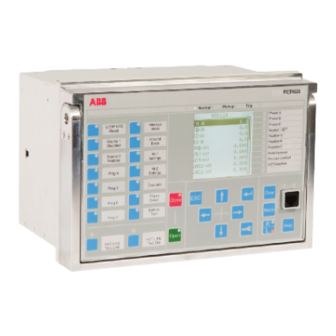
ABB RER620 Technical Manual (584 pages)
Advanced Recloser Protection and Control
Brand:
ABB
| Category:
Power distribution unit
| Size: 15 MB
Table of Contents
Table of Contents
7
Introduction
23
This Manual
23
Intended Audience
23
Section 1 Introduction
23
Product Documentation
24
Product Documentation Set
24
Document Revision History
25
Related Documentation
25
Symbols and Conventions
25
Safety Indication Symbols
25
Manual Conventions
26
Functions, Codes and Symbols
27
RER620 Overview
31
Overview
31
Product Series Version History
31
PCM600 and Relay Connectivity Package Version
31
Section 2 RER620 Overview
31
Local HMI
32
Lcd
32
Leds
33
Keypad
33
Web HMI
34
Authorization
35
Communication
36
Basic Functions
37
General Parameters
37
Section 3 Basic Functions
37
Self-Supervision
51
Internal Faults
51
Warnings
52
LED Indication Control
56
Time Synchronization
56
Parameter Setting Groups
57
Recorded Data
58
Non-Volatile Memory
60
Binary Input
60
Binary Input Filter Time
60
Binary Input Inversion
61
Oscillation Suppression
62
GOOSE Function Blocks
62
GOOSERCV_BIN Function Block
63
Function Block
63
Functionality
63
Signals
63
GOOSERCV_DP Function Block
63
Signals
64
GOOSERCV_MV Function Block
64
Function Block
64
Functionality
64
GOOSERCV_INT8 Function Block
65
Function Block
65
Functionality
65
Signals
65
GOOSERCV_INTL Function Block
65
Signals
66
GOOSERCV_CMV Function Block
66
Function Block
66
Functionality
66
GOOSERCV_ENUM Function Block
67
Function Block
67
Functionality
67
Signals
67
GOOSERCV_INT32 Function Block
67
Functionality
68
Signals
68
Type Conversion Function Blocks
68
QTY_GOOD Function Block
68
Function Block
68
Signals
69
QTY_BAD Function Block
69
Function Block
69
Functionality
69
T_HEALTH Function Block
70
Function Block
70
Functionality
70
Signals
70
T_F32_INT8 Function Block
70
Functionality
71
Settings
71
Configurable Logic Blocks
71
Standard Configurable Logic Blocks
71
OR Function Block
71
AND Function Block
73
XOR Function Block
74
NOT Function Block
75
MAX3 Function Block
76
MIN3 Function Block
76
R_TRIG Function Block
77
F_TRIG Function Block
78
T_POS_XX Function Blocks
79
SR Function Block
81
PH_ORD_IN Block
82
PH_ORD_OUT Block
83
Local/Remote Control Function Block CONTROL
84
Function Block
84
Functionality
85
Signals
86
Settings
86
Monitored Data
87
Factory Settings Restoration
87
Protection Functions
89
Current Protection
89
Single-Phase Non-Directional Overcurrent Protection 51P/50P
89
Identification
89
Function Block
89
Functionality
89
Operation Principle
89
Section 4 Protection Functions
89
Measurement Modes
93
Timer Characteristics
93
Application
95
Signals
100
Settings
101
Monitored Data
104
Technical Data
105
Technical Revision History
106
Single-Phase Directional Overcurrent Protection 67/51P-1 and 67/51P-2
106
Identification
106
Function Block
106
Functionality
106
Operation Principle
107
Measuring Modes
112
Directional Overcurrent Characteristics
112
Application
120
Signals
122
Settings
123
Monitored Data
128
Technical Data
130
Non-Directional Neutral Overcurrent Protection 51N/50N
130
Identification
130
Function Block
131
Functionality
131
Operation Principle
131
Measurement Modes
133
Timer Characteristics
133
Application
136
Signals
137
Settings
139
Monitored Data
142
Technical Data
143
Directional Earth-Fault Protection 67/51N and 67/50N
143
Identification
143
Function Block
144
Functionality
144
Operation Principle
144
Directional Ground-Fault Principles
148
Measurement Modes
154
Timer Characteristics
155
Directional Ground-Fault Characteristics
157
Application
167
Signals
169
Settings
170
Monitored Data
175
Technical Data
176
Sensitive Earth-Fault Protection 50SEF
176
Identification
176
Function Block
177
Functionality
177
Principle of Operation
177
Measurement Modes
177
Timer Characteristics
177
Application
177
Signals
177
Settings
177
Monitored Data
177
Technical Data
177
Negative Phase-Sequence Current Protection 46
178
Identification
178
Function Block
178
Functionality
178
Operation Principle
178
Application
180
Signals
182
Settings
182
Monitored Data
184
Technical Data
184
Phase Discontinuity Protection 46PD
185
Identification
185
Function Block
185
Functionality
185
Operation Principle
185
Application
187
Signals
188
Settings
189
Monitored Data
189
Technical Data
189
Three-Phase Transformer Inrush Detector INR
190
Identification
190
Function Block
190
Functionality
190
Operation Principle
190
Application
192
Signals
193
Settings
193
Monitored Data
193
Technical Data
194
Cold Load Timers
194
Voltage Protection
194
Single-Phase Overvoltage Protection 59
194
Identification
194
Function Block
195
Functionality
195
Operation Principle
195
Timer Characteristics
200
Application
200
Signals
201
Settings
201
Monitored Data
202
Technical Data
203
Single-Phase Undervoltage Protection 27
203
Identification
203
Function Block
203
Functionality
204
Operation Principle
204
Timer Characteristics
209
Application
209
Signals
210
Settings
210
Monitored Data
211
Technical Data
212
Zero Sequence Overvoltage Protection 59N
212
Identification
212
Function Block
212
Functionality
212
Operation Principle
213
Application
214
Signals
214
Settings
215
Monitored Data
215
Technical Data
215
Positive Sequence Overvoltage Protection 59PS
216
Identification
216
Function Block
216
Functionality
216
Operation Principle
216
Application
217
Signals
217
Settings
218
Technical Data
218
Negative Sequence Overvoltage Protection 47
219
Identification
219
Function Block
219
Functionality
219
Operation Principle
219
Application
220
Signals
221
Settings
221
Monitored Data
221
Technical Data
222
Frequency Protection
222
Frequency Protection 81O/81U, 81R
222
Identification
222
Function Block
223
Functionality
223
Operation Principle
223
Application
226
Signals
227
Settings
228
Monitored Data
228
Technical Data
229
Load Shedding and Restoration 81S
229
Identification
229
Function Block
229
Functionality
229
Operation Principle
230
Application
235
Signals
239
Settings
240
Monitored Data
240
Technical Data
240
Other Protection Functions Available in RER620
241
Circuit Breaker Failure Protection 50BFT
241
Identification
241
Function Block
241
Functionality
241
Operation Principle
241
Application
247
Signals
248
Settings
249
Monitored Data
249
Technical Data
249
Single Phase Circuit Breaker Close Failure Protection 50BFC
250
Identification
250
Function Block
250
Functionality
250
Operation Principle
250
Signals
253
Settings
254
Monitored Data
254
Technical Data
254
High Impedance Fault Detector HIZ
254
Identification
254
Function Block Symbol
255
Functionality
255
Principle of Operation
255
Application
257
Signals
258
Settings
258
Monitored Data
258
Fault Locator FLOC
259
Identification
259
Function Block
259
Functionality
259
Operation Principle
259
Application
263
Signals
264
Settings
264
Monitored Data
264
Directional Positive Sequence Power Protection 32P
265
Identification
265
Function Block
265
Functionality
265
Operation Principle
265
Application
267
Signals
268
Settings
268
Monitored Data
269
Technical Data
269
Directional Negative/Zero Sequence Power Protection 32N
269
Identification
269
Function Block
270
Functionality
270
Operation Principle
270
Application
276
Signals
276
Settings
277
Monitored Data
277
Technical Data
277
Control Functions
279
Circuit Breaker Control 52
279
Identification
279
Function Block
279
Functionality
279
Section 5 Control Functions
279
Operation Principle
280
Application
282
Signals
284
Settings
286
Monitored Data
286
Autoreclosing 79
286
Identification
288
Function Block
289
Supporting Function Blocks
289
Functionality
289
Single Phase Tripping
290
Protection Signal Definition
291
Operation Principle
291
Active Phases Determination with SDAIGGIO Blocks
293
Autorecloser Function (Core)
295
Output Interface with SDAOGGIO Block
309
Zone Sequence Coordination
310
Counters
311
Application
311
Single Phase Tripping
312
Configuration Examples
316
Signals
320
Settings
323
Monitored Data
326
79 Technical Data
329
Synch-Check/Voltage Check 25
329
Identification
329
Function Block
329
Functionality
329
Operation Principle
330
Application
337
Signals
339
Settings
340
Monitored Data
341
25 Technical Data
342
Loop Control (DLCM)
342
Identification
342
Function Block
342
Functionality
342
Sectionalizing Recloser
343
Midpoint Recloser
344
Tiepoint Recloser
344
Operation Principle
344
Application
349
Three-Recloser Loop Control
350
Five-Recloser Loop Control
352
Four-Recloser System Operation
356
Restoring Normal Operation
356
Signals
357
Settings
358
Multipurpose Generic Up-Down Counter (UDFCNT)
359
Identification
359
Function Block
359
Functionality
359
Operation Principle
359
Signals
361
Settings
361
Condition Monitoring Functions
363
Circuit Breaker Condition Monitoring 52CM
363
Identification
363
Function Block
363
Functionality
363
Operation Principle
364
Circuit Breaker Status
366
Circuit Breaker Operation Monitoring
366
Breaker Contact Travel Time
367
Operation Counter
369
Accumulation of I y T
370
Remaining Life of the Circuit Breaker
371
Circuit Breaker Spring Charged Indication
373
Gas Pressure Supervision
373
Application
374
Signals
378
Settings
380
Monitored Data
381
Technical Data
381
Fuse Failure Supervision 60
382
Identification
382
Function Block
382
Functionality
382
Operation Principle
382
Application
385
Signals
387
Settings
387
Monitored Data
388
Technical Data
388
Measurement Functions
389
Basic Measurements
389
Functions
389
Measurement Functionality
389
Section 7 Measurement Functions
389
Measurement Function Applications
397
Three-Phase Current IA, IB, IC
398
Identification
398
Function Block
398
Signals
398
Settings
399
Monitored Data
400
Technical Data
401
Three-Phase Voltage VA, VB, VC
401
Identification
401
Function Block
401
Signals
401
Settings
402
Monitored Data
403
Technical Data
403
Ground Current IG
404
Identification
404
Function Block
404
Signals
404
Settings
404
Monitored Data
405
Technical Data
405
Ground Voltage VG
405
Identification
405
Function Block
405
Signals
405
Settings
406
Monitored Data
406
Technical Data
406
Sequence Current I1, I2, I0
407
Identification
407
Function Block
407
Signals
407
Settings
408
Monitored Data
409
Technical Data
409
Phase Sequence Voltage V1, V2, V0
409
Identification
409
Function Block
410
Signals
410
Settings
410
Monitored Data
411
Technical Data
411
Single and Three-Phase Power, Powerfactor and Three Phase Energy Measurement P, SP, E
412
Identification
412
Function Block
412
Signals
412
Settings
413
Monitored Data
414
Technical Data
416
Frequency
416
Identification
416
Function Block
417
Signals
417
Settings
417
Monitored Data
417
Technical Data
417
Recording Functions
419
Digital Fault Recorder DFR (RDRE)
419
Functionality
419
Recorded Analog Inputs
419
Triggering Alternatives
419
Section 8 Recording Functions
419
Length of Recordings
421
Sampling Frequencies
421
Uploading of Recordings
421
Deletion of Recordings
422
Storage Mode
422
Pre-Trigger and Post-Trigger Data
423
Operation Modes
423
Exclusion Mode
424
Configuration
424
Application
425
Settings
426
Monitored Data
427
Other Functions
429
Uninterruptible Power Supply UPS
429
Function Block
429
Functionality
429
Section 9 Other Functions
429
Input Power Requirements
431
Input Power Measurement
432
Loss of UPS Input Power Alarm
432
Battery Management
433
Auxiliary Power Supply
434
Actuator Drive Power Source (Boost Supply)
434
Heater Control Switch
434
RER620 Power
435
RS485 Communications
435
Connections
436
Signals
437
CVD Voltage Clamping
437
Settings
440
Monitored Data
441
Universal Power Drive UPD
442
Function Block
442
Functionality
442
Connections
445
Signals
446
Settings
446
Monitored Data
446
Programmable Buttons FKEYGGIO
447
Function Block
447
Functionality
447
Signals
448
Move Function Block MVGAPC
449
Function Block
449
Functionality
449
Signals
449
Pulse Timer Function Block PTGAPC
450
Function Block
450
Functionality
450
Signals
451
Settings
452
Technical Data
452
Generic Control Points SPCGGIO
453
Function Block
453
Functionality
453
Signals
454
Settings
455
Set-Reset Flip Flops SRGAPC
455
Function Block
455
Functionality
455
Signals
456
Settings
457
Time-Delay-Off Timers TOFGAPC
458
Function Block
458
Functionality
458
Signals
459
Settings
460
Technical Data
460
Time-Delay-On Timers TONGAPC
461
Function Block
461
Functionality
461
Signals
462
Settings
463
Technical Data
463
Section 10 General Function Block Features
465
Definite Time Characteristics
465
Definite Time Operation
465
Current Based Inverse Definite Minimum Time Characteristics
469
IDMT Curves for Overcurrent Protection
469
Standard Inverse-Time Characteristics
471
Recloser Inverse-Time Characteristics
486
User-Programmable Inverse-Time Characteristics
527
RI and RD-Type Inverse-Time Characteristics
527
Reset in Inverse-Time Modes
530
Inverse-Timer Freezing
539
Voltage Based Inverse Definite Minimum Time Characteristics
540
IDMT Curves for Overvoltage Protection
540
Standard Inverse-Time Characteristics for Overvoltage Protection
543
User Programmable Inverse-Time Characteristics for Overvoltage Protection
546
IDMT Curve Saturation of Overvoltage Protection
547
Standard Inverse-Time Characteristics for Undervoltage Protection
548
IDMT Curve Saturation of Undervoltage Protection
551
Section 11 Requirements for Measurement Transformers
555
Non-Directional Overcurrent Protection
556
Example for Non-Directional Overcurrent Protection
557
Section 12 Relay Physical Connections
559
Ethernet RJ-45 Front Connection
560
EIA-485 Serial Rear Connection
561
Rear Communication Modules
562
COMB022/23A Jumper Locations and Connections
563
Section 13 Technical Data
569
Section 14 Relay and Functionality Tests
575
Section 15 Applicable Standards and Regulations
577
Section 16 Glossary
579
Advertisement
ABB RER620 Applications Manual (90 pages)
Advanced Recloser Protection and Control
Brand:
ABB
| Category:
Protection Device
| Size: 3.71 MB
Table of Contents
Table of Contents
7
Introduction
9
This Manual
9
Intended Audience
9
Product Documentation
10
Product Documentation Set
10
Document Revision History
11
Related Documentation
11
Symbols and Conventions
11
Safety Indication Symbols
11
Manual Conventions
12
Functions, Codes and Symbols
13
RER620 Overview
17
Overview
17
Product Version History
17
PCM600 and Relay Connectivity Package Version
17
Physical Hardware
18
Local HMI
20
Lcd
21
Leds
21
Keypad
21
Web HMI
22
Authorization
23
Communication
24
RER620 Application
27
Applications
27
Functions
28
Default LED Connections
30
One Touch Functions
31
Connection Diagrams
33
Functional Diagrams
35
Functional Diagrams for Protection
37
Functional Diagrams for Control and Autoreclosing
50
Functional Diagrams for Measurements
59
Functional Diagram for Digital Fault Recorder
61
Output Leds
62
Auto Reclose
62
Overview of the Features in Single-Phase Tripping
63
Conditions on Single Phase Tripping
63
OPUP Mode - Only Picked up Phases
64
OOAP Mode - One or All Phases
64
APAT: (All Poles All the Time)
65
Autorecloser Logic
65
Input Function Blocks (Sdaiggios)
66
Auto Recloser Block (SDARREC)
68
Output Interface Block (SDAOGGIO)
68
Loop Control Module
69
Sectionalizing Recloser
69
Midpoint Recloser
69
Tiepoint Recloser
70
DLCM Function Block
70
Phase Selection
70
Phase Status Determination
72
Resetting DLCM Function
73
Hot Line Tag Functionality
73
Requirements for Measurement Transformers
77
Current Transformers
77
Current Transformer Requirements for Non-Directional Overcurrent Protection
77
Current Transformer Accuracy Class and Accuracy Limit Factor
77
Non-Directional Overcurrent Protection
78
Example for Non-Directional Overcurrent Protection
79
Relay Physical Connections
81
Inputs
81
Phase Currents
81
Ground Current
81
Phase Voltages
81
Auxiliary Supply Voltage Input
81
Binary Inputs
82
Outputs
83
Outputs for Tripping and Controlling
83
Outputs for Signaling
83
Irf
84
Upd
85
Glossary
87
ABB RER620 Communication Protocol Manual (40 pages)
IEC 60870-5-101/104 Communication Protocol Manual
Brand:
ABB
| Category:
Relays
| Size: 0.73 MB
Table of Contents
Table of Contents
7
Introduction
11
This Manual
11
Intended Audience
11
Product Documentation
12
Product Documentation Set
12
Document Revision History
13
Related Documentation
13
Symbols and Conventions
13
Safety Indication Symbols
13
Manual Conventions
14
IEC 60870-5 Overview
15
IEC 60870-5 Protocol
15
Transmission
15
Unbalanced Transmission
16
Balanced Transmission
16
Basic Application Functions
16
Data Acquisition
16
Event Acquisition
17
Interrogation
17
Clock Synchronization
17
Command Transmission
17
Changes in Protocol and Link Parameters
18
Acquisition of Transmission Delay
18
Analog Value Deadband
18
Vendor-Specific Implementation
19
615/620 Series Implementation
19
Internal IEC 61850 Data Modeling
19
Instances
19
Selecting between IEC 60870-5-101 and IEC 60870-5-104
19
Configuring
19
Configuring IEC 60870-5-101
20
Configuring IEC 60870-5-104
20
Troubleshooting
21
Event Overflow Handling
21
Overflow Mode
21
Overflow Indication Addresses
21
Overflow Situation Clearing
22
Supported Data Types
22
Indications (MSP, MDP)
22
Measurements (MMENA, MMENB, MMENC, MMEND)
22
Control Objects (CSC, CDC)
22
Addressing Scheme
23
Default Addresses
23
Configuring Communication Options
23
Communication Parameters
23
Port
23
Clientip
23
End Delay
24
Device Address
24
ASDU Address
24
Link Mode
25
COT Length
25
OA Length
25
Link Address Length
25
ASDU Address Length
25
Single Character Response
26
Show Bad Time
26
Time Format
26
Event Time
27
Overflow Mode
27
Ovind IOA
27
Ovind Nogi IOA
27
Event Order
28
Selection Time-Out
28
Cyclical Period
29
Transmit Window
29
Receive Window
29
Transmit Timeout
29
Receive Timeout
29
Link Test Interval
30
Diagnostics
30
Status
30
Received Frames
30
Transmitted Frames
30
Physical Errors
31
Link Errors
31
Transport Errors
31
IEC 60870-5-101 and IEC 60870-5-104 Parameters
33
Parameter List
33
Monitored Data
35
Advertisement
ABB RER620 Installation Manual (48 pages)
Protection and Control
Brand:
ABB
| Category:
Controller
| Size: 0.87 MB
Table of Contents
Table of Contents
9
Introduction
11
This Manual
11
Intended Audience
11
Section 1 Introduction
11
Product Documentation
12
Product Documentation Set
12
Document Revision History
13
Related Documentation
13
Symbols and Conventions
13
Safety Indication Symbols
13
Manual Conventions
14
Environmental Aspects
15
Sustainable Development
15
Disposing of the IED
15
Section 2 Environmental Aspects
15
Unpacking, Inspecting, and Storing
17
Removing Transport Packaging
17
Inspecting the Product
17
Identifying the Product
17
Checking Delivery Items
17
Inspecting the IED
17
Returning an IED Damaged in Transit
17
Storing
18
Mounting
19
Checking Environmental Conditions and Mounting Space
19
Detaching and Installing the Plug-In Unit
19
Detaching the Plug-In Unit
19
Section 4 Mounting
19
Installing the Plug-In Unit
20
Sealing the Plug-In Unit
21
Mounting the IED
22
Flush Mounting the IED
22
Connecting
27
Required Tools
27
Connecting Wires
27
Connecting Ring-Lug Type Wires
27
Connecting Protective Grounding
27
Section 5 Connecting
27
Connecting Analog Signals
28
Connecting Current Inputs
29
Connecting Voltage Inputs
29
Connecting IED with a Test Switch
30
Connecting Power Supply
30
Connecting Communication
32
Energizing the IED
33
Removing, Repairing and Exchanging
35
Product Lifecycle
35
Checking IED Information
35
Removing the IED
36
Sending the IED for Repair
36
Exchanging the IED
37
Technical Data
39
Case and HMI Display Variants
39
Front Side of the IED
39
Section 7 Technical Data
39
Rear Side of the IED
40
Dimensions
41
Enclosure Class
42
Glossary
43
Section 8 Glossary
43
ABB RER620 Manual (60 pages)
Advanced Recloser Protection and Control IEC 60870-5-101/104 Point List Manual
Brand:
ABB
| Category:
Controller
| Size: 0.71 MB
Table of Contents
Table of Contents
7
Introduction
9
This Manual
9
Intended Audience
9
Product Documentation
10
Product Documentation Set
10
Document Revision History
11
Related Documentation
11
Symbols and Conventions
11
Safety Indication Symbols
11
Manual Conventions
12
Functions, Codes and Symbols
13
IEC 60870-5-101/104 Data Mappings
17
Overview
17
Point List for RER620 Ver. 1.0
18
IEC 60870-5-101/104 Protocol Implementation
45
Glossary
57
ABB RER620 Product Manual (44 pages)
Advanced recloser protection & control
Brand:
ABB
| Category:
Protection Device
| Size: 2.61 MB
Table of Contents
Table of Contents
2
Description
3
Standard Configurations
4
Protection Functions
6
Application
8
Supported ABB Solutions
12
Control
14
Measurements
14
Digital Fault Recorder
14
Event Recorder
14
Fault Recorder
14
Recloser/Circuit Breaker Condition Monitoring
15
Trip-Circuit Monitoring
15
Self-Diagnostics
15
Fuse Failure Protection
15
Uninterruptable Power Supply (UPS)
15
Universal Power Driver (UPD)
16
Access Control
16
Inputs and Outputs
16
Communications
16
Display
33
Local HMI
34
Mounting Methods
35
Protection and Control Relay Case and Drawout Unit
35
Selection and Ordering Data
36
Accessories and Ordering Data
37
Tools
37
Terminal Diagrams
39
Certificates
40
Functions, Codes, and Symbols
40
References
40
Document Revision History
43
Advertisement
Related Products
ABB REJ603
ABB RELION REX640
ABB RELION REV615
ABB REG630
ABB RELION REM611
ABB REU611
Abb RER601
Abb RER603
ABB RELION RER670
ABB Relion RER615
ABB Categories
Industrial Equipment
Controller
Measuring Instruments
Battery Charger
DC Drives
More ABB Manuals
Login
Sign In
OR
Sign in with Facebook
Sign in with Google
Upload manual
Upload from disk
Upload from URL