Sign In
Upload
Manuals
Brands
ABB Manuals
Media Converter
ACS880-1604
ABB ACS880-1604 Manuals
Manuals and User Guides for ABB ACS880-1604. We have
2
ABB ACS880-1604 manuals available for free PDF download: Hardware Manual
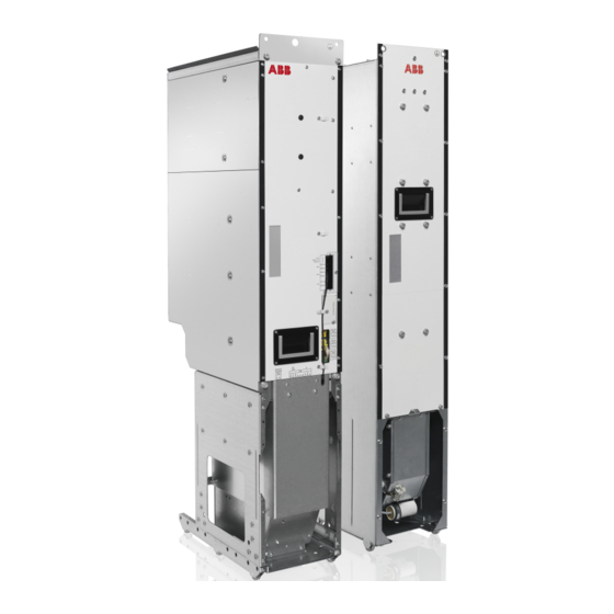
ABB ACS880-1604 Hardware Manual (222 pages)
DC/DC converter modules
Brand:
ABB
| Category:
Media Converter
| Size: 28.03 MB
Table of Contents
Table of Contents
5
1 Introduction to the Manual
13
Contents of this Chapter
13
Applicability
13
Safety Instructions
13
Target Audience
13
Contents of the Manual
14
Related Documents
14
Categorization by Frame Size and Option Code
14
Use of Component Designations
14
Terms and Abbreviations
15
2 Operation Principle and Hardware Description
17
Contents of this Chapter
17
Operation Principle
18
Main Circuit Diagram
19
Charging Circuit
19
Charging Circuit
20
Main Circuit Diagram of Parallel-Connected DC/DC Converter Modules
21
Overview Diagram of a Drive with a DC/DC Converter Unit
22
Single-Line Circuit Diagram of the DC/DC Converter Unit
23
Hardware Description
24
R8I and BDCL Filter Modules
24
DC Bus Connection and Capacitor Charging
24
Layout Drawings
25
R8I DC/DC Converter Module
25
Converter Module Connectors X50
26
BDCL Filter Module
27
Filter Module Connectors X30 and X55
28
Overview of the Control Connections on the BCU Control Unit
29
Converter Unit Control Devices
30
DC Switch/Disconnector
30
Charging Switch
30
Door Lights
30
BCU Control Unit
30
ACS-AP-X Control Panel
30
PC Connection
31
Fieldbus Control
31
Type Designation Labels
32
Type Designation Labels of the DC/DC Converter Module
32
Type Designation Label of the BDCL Filter Module
33
Type Designation Key
34
Type Designation of the Converter Module
34
Type Designation of the Filter Module
35
3 Moving and Unpacking the Module
37
Contents of this Chapter
37
Moving and Lifting the Transport Package
37
Unpacking
37
Lifting the Modules
38
Moving the Modules
38
4 Cabinet Construction
39
Contents of this Chapter
39
Liability
39
Energy Storage
39
Cooling and Mounting Orientations
39
Cabinet Configuration Overview
40
ACS880-1604 Configuration in Rittal TS 8 and Generic Enclosures
40
Installation Examples
41
1×R8I DDC Unit in a 800 MM Wide Rittal TS 8 Enclosure
42
Layout with DC Switch/Disconnector and Charging
42
Layout Without DC Switch/Disconnector and Charging
43
Installation Stages
44
Kits for DDC R8I Unit in 800 MM Rittal TS 8 Enclosure
45
Stage 1: Installation of Common Parts
46
Stage 2: Module and Bottom Cable Entry Installation Parts
47
Stage 3: Busbars and Quick Connectors for Connecting DDC Module and Filter
48
Stage 4A: DC Connection with Charging
49
Stage 4B: DC Connection Without Charging
50
Stage 5A: DC Connection with Charging
51
Stage 5B: DC Connection Without Charging
52
Stage 6: DDC and Energy Storage Connection
53
Stage 7: Control Unit Mounting Plate
54
Stage 8: DDC Shroud Installation
55
Stage 9: DDC Module and Filter Installation
56
1×R8I DDC Unit in a 800 MM Wide Generic Enclosure
57
Parts to be Installed
57
Kits for DDC R8I Unit in 800 MM Wide Generic Enclosure
58
5 Guidelines for Planning Electrical Installation
59
Contents of this Chapter
59
Liability
59
Generic Guidelines
59
Selecting the Energy Storage
60
Disconnection of Energy Storage at the Storage End
61
Implementing Load Current Switch-Off
61
Selecting and Routing the Energy Storage Cables
62
Recommended Cables
62
Typical Cable Sizes
62
Minimizing Electromagnetic Interference
63
Maximum Cable Length
63
EMC Compliance of the Complete Installation
63
Protecting the System against Thermal Overload
63
Protecting the Energy Storage Cable against Short-Circuits
63
6 Electrical Installation
65
Contents of this Chapter
65
Safety and Liability
65
Electrical Safety Precautions
66
General Notes
67
Static Electricity
67
Optical Components
67
Checking the Insulation of the Energy Storage Cable
68
Connecting the Power Cables
69
Connection Diagram (Frame 1×R8I)
69
Connection Procedure for Power Connections Inside the DC/DC Converter Cubicle
70
Connection Procedure for Energy Storage Cables
72
Connecting the BDCL Filter
73
Internal Circuit Diagram for the BDCL Filter
74
Installing the Charging Circuit
75
Connecting the External Power Supply Cable for the Auxiliary Circuit
75
R8I DC/DC Converter Module
75
BDCL Filter Module
75
Connecting the Control Cables
76
Default I/O Connection Diagram
76
Connection Procedure
76
Fiber Optic Connectors of the DC/DC Converter Module
77
Installing Optional Modules
78
Connecting a PC
79
7 Installation Checklist
81
Contents of this Chapter
81
Warnings
81
Checklist
82
8 Start-Up
83
Contents of this Chapter
83
Start-Up Procedure
84
Safety
84
Checks/Settings with no Voltage Connected
84
Connecting Voltage to the Drive and Converter Control Unit
84
Setting the Parameters
85
Charging the DC/DC Converter and Connecting Voltage to the Converter
85
Connecting the Energy Storage to the DC/DC Converter
85
Testing the DC/DC Converter Operation
86
Disconnecting the DC/DC Converter with DC Switch/Disconnector
87
Safety
87
Stopping the DC/DC Converter
87
Disconnecting the Energy Storage
87
Disconnecting the DC/DC Converter
87
Working Inside the DC/DC Converter Cubicle
87
Reconnecting the DC/DC Converter with DC Switch/Disconnector
88
Safety
88
Reconnecting the DC/DC Converter
88
Starting the DC/DC Converter
88
9 Maintenance
89
Contents of this Chapter
89
Maintenance Intervals
90
Maintenance Timers and Counters
91
Cabinet
91
Cleaning the Interior of the Cabinet
91
Cleaning the Door Air Inlets (IP42)
92
Cleaning the Door Air Inlets (IP54)
93
Cleaning the Outlet (Roof) Filters (IP54)
93
Power Connections
94
Retightening the Power Connections
94
Fans
95
Replacing the Cabinet Cooling Fan
95
Replacing the Speed-Controlled Cooling Fan of the DC/DC Converter Module
96
Replacing the Direct-On-Line Fan (Option +C188) of the DC/DC Converter Module
98
Replacing the Circuit Board Compartment Fan
100
Replacing the Fan of the BDCL Filter
103
Replacing the Roof Fan for IP54 Cabinet
104
Cabinets with ABB Air Outlet Kits
104
Cabinets with Other Fan Types
104
DC/DC Converter Module
105
Cleaning the Module
105
Replacing the R8I DC/DC Converter Module
106
BDCL Filter
110
Replacing the BDCL Filter
110
Capacitors
114
Reforming the Capacitors
114
Control Panel
115
Replacing the Control Panel Battery
115
Cleaning the Control Panel
115
Control Unit
116
BCU Control Unit Types
116
Memory Unit
116
Control Unit Battery
117
Leds and Other Status Indicators
118
10 Ordering Information
119
Contents of this Chapter
119
Kit Code
120
DC/DC Converter Modules
121
BDCL Filters
122
BDCL Filters (+C188)
122
BDCL Filters (+C188+G304)
123
Control Panel
124
Control Electronics
126
Control Unit
126
Fiber Optic Cables
127
Control Circuit Plug Connectors
127
Mechanical Installation Accessories and Tools
128
Module Installation Parts
128
Shrouds
129
Ramp
129
Bottom Cable Entry
130
Control Unit Mounting Plate
130
Electrical Installation Accessories
131
Busbars and Quick Connectors for Connecting DDC Module and Filter
131
Common DC Flat-PLS Assembly
132
DC Connection with DC Switch/Disconnector and Charging
133
DC Connection Without DC Switch/Disconnector and Charging
134
Energy Storage Connection
136
DC Fuses (DC Bus Side)
137
Output DC Fuses (Energy Storage Side)
137
DC Switch/Disconnector Kits
138
DC Switch/Disconnectors (IEC, 230 V, 50 Hz)
138
DC Switch/Disconnectors (IEC, 240 V, 60 Hz)
138
DC Switch/Disconnectors (UL/CSA, 110 V, 60 Hz)
139
Charging Kits
140
Charging Kits (IEC)
140
Charging Kits (UL)
141
Cabinet Ventilation Kits
142
Air Inlet Kits
142
Air Outlet Kits
143
Cooling Fans
145
Roof Fans
145
Internal Cabinet Fan
145
Miscellaneous
146
BAMU Voltage/Current Measurement Unit
146
11 Technical Data
147
Contents of this Chapter
147
Ratings
148
Definitions
149
Derating
150
Temperature Derating
150
Altitude Derating
150
Type Equivalence Table
151
Fuses
151
Fuses on BFPS Board
151
Fuses and Fuse Bases for BAMU Unit
151
Charging Component Ratings
151
Dimensions and Weights
152
R8I DC/DC Converter Module
152
BDCL Filter Module
152
Free Space Requirements
152
Allowable Mounting Orientations
153
Losses, Cooling Data and Noise
153
Tightening Torques
154
Cable Lugs
154
Electrical Connections
154
Mechanical Connections
154
Insulation Supports
154
Input Power (DC Bus) Connection
155
Output Power (Energy Storage) Connection
155
Control Accuracy - Current and Voltage Control Performance Data
156
Control Unit Connection Data
156
Optical Components
156
Degree of Protection
156
Ambient Conditions
157
Materials
158
Auxiliary Current Consumption
159
Cooling Fans
159
Applicable Standards
159
Markings
159
Disclaimer
160
Generic Disclaimer
160
Cybersecurity Disclaimer
160
12 Control Unit
161
Contents of this Chapter
161
General
161
Default I/O Connection Diagram
162
External Power Supply for the Control Unit (XPOW)
163
SDHC Memory Card Slot
163
Layout and Connections
164
Control Unit Connector Data
166
Ground Isolation Diagram
168
13 Dimension Drawings
169
Contents of this Chapter
169
R8I DC/DC Converter Module
170
Quick Connectors of the DC/DC Converter Module
172
Quick Connectors
173
BDCL Filter Module
174
ACS-AP-X Control Panel with Door Mounting Kit
175
BCU Control Unit
176
BAMU Voltage/Current Measurement Unit
177
BAMU Fuse Holders and Fuses
178
PS272PREMCPS Fuse Disconnector and PS27 Terminal Cover
178
Fuse, 27 × 60 MM
178
Ramp
179
Internal Cabinet Fan
181
W2E 143-Aa09-01, W2E 143-Aa15-01
181
Switchgear and Charging Components
182
DC Switch/Disconnectors
182
Ot1600E11 (Iec), Ot1200U11 (Ul)
182
Charging Switches
183
Os160Gd04F (Iec)
183
Os100Gj04Fp (Ul/Csa)
184
Charging Controller
185
Resistors
186
Zrf 30X165
186
Handles
186
Ohb65J6
186
Contacts
187
Auxiliary Contact OA3G01
187
DC Fuses
188
170M6415, 170M6419, 170M6545, 170M6549
188
170M6545, 170M6549
189
14 Example Circuit Diagrams
191
Contents of this Chapter
191
Component Designations Used in the Diagrams
192
DC/DC Converter 1×R8I and 2×R8I Without DC Switch/Disconnector
192
DC/DC Converter 1×R8I and 2×R8I with DC Switch/Disconnector
193
DDC 1×R8I Without DC Switch/Disconnector
195
Sheet 001 (DC Main Circuit)
195
Sheet 005 (Module Connections)
196
Sheet 020 (Auxiliary Voltage Distribution)
197
Sheet 040 (Control Unit)
198
Sheet 041 (BAMU Measurement Unit)
199
DDC 1×R8I with DC Switch/Disconnector
200
Sheet 001 (DC Main Circuit, Charging Circuit)
200
Sheet 005 (Module Connections)
201
Sheet 020 (Auxiliary Voltage Distribution)
202
Sheet 040 (Control Unit)
203
Sheet 041 (BAMU Measurement Unit)
204
DDC 2×R8I Without DC Switch/Disconnector
205
Sheet 001 (DC Main Circuit)
205
Sheet 002 (DC Main Circuit)
206
Sheet 005 (Module Connections)
207
Sheet 006 (Module Connections)
208
Sheet 020 (Auxiliary Voltage Distribution)
209
Sheet 021 (Auxiliary Voltage Distribution)
210
Sheet 040 (Control Unit)
211
Sheet 041 (BAMU Measurement Unit)
212
DDC 2×R8I with DC Switch/Disconnector
213
Sheet 001 (DC Main Circuit, Charging Circuit)
213
Sheet 002 (DC Main Circuit, Charging Circuit)
214
Sheet 005 (Module Connections)
215
Sheet 006 (Module Connections)
216
Sheet 020 (Auxiliary Voltage Distribution)
217
Sheet 021 (Auxiliary Voltage Distribution)
218
Sheet 040 (Control Unit)
219
Sheet 041 (BAMU Measurement Unit)
220
Further Information
221
Product and Service Inquiries
221
Product Training
221
Providing Feedback on ABB Drives Manuals
221
Document Library on the Internet
221
Advertisement
ABB ACS880-1604 Hardware Manual (208 pages)
Industrial Drives DC/DC converter modules
Brand:
ABB
| Category:
Control Unit
| Size: 53.67 MB
Table of Contents
Table of Contents
5
1 Introduction to the Manual
13
Contents of this Chapter
13
Applicability
13
Safety Instructions
13
Target Audience
13
Categorization by Frame Size and Option Module
14
Use of Component Designations
14
Terms and Abbreviations
14
Related Documents
15
2 Operation Principle and Hardware Description
17
Contents of this Chapter
17
Operation Principle
17
Main Circuit Diagram
18
Overview Diagram of a Drive with a DC/DC Converter Unit
20
Single-Line Circuit Diagram of the DC/DC Converter Unit
21
Converter Module Hardware
22
Frame R8I Layout
22
Connectors X50
23
Frame R8I Hardware
24
DC Bus Connection and Capacitor Charging
24
BDCL Filter Module
25
Connectors X30 and X55
26
BCU Control Unit of Frame R8I and Multiples
26
Overview of the Control Connections of the BCU Control Unit
27
Converter Unit Control Devices
28
DC Switch/Disconnector
28
Charging Switch
28
Door Lights
28
BCU Control Unit
28
ACX-AP-X Control Panel
28
PC Connection
29
Fieldbus Control
29
BAMU Voltage/Current Measurement Unit
29
I/O Module
29
Type Designation Labels
30
Type Designation Labels of the DC/DC Converter Module
30
Type Designation Label of the BDCL Filter Module
31
Type Designation Key
31
Type Designation of the Module
31
Type Designation Key of the Filter Module
32
3 Moving and Unpacking the Module
33
Contents of this Chapter
33
Moving and Lifting the Transport Package
33
Unpacking
33
Lifting the Modules
33
Moving the Modules
34
4 Cabinet Construction
35
Contents of this Chapter
35
Limitation of Liability
35
Energy Storage
35
Cooling and Mounting Orientations
35
Cabinet Configuration Overview
36
ACS880-1604 Configuration in Rittal VX25 and Generic Enclosure
36
Installation Examples
37
1×R8I DDC Unit in a 800 MM Wide Rittal VX25 Enclosure
38
Layout with DC Switch/Disconnector and Charging
38
Layout Without DC Switch/Disconnector and Charging
39
Installation Stages
40
Kits for DDC R8I Unit in 800 MM Rittal VX25 Enclosure
41
Stage 1: Installation of Common Parts
42
Stage 2: Module and Bottom Cable Entry Installation Parts
43
Stage 3: Busbars and Quick Connectors for Connecting DDC Module and Filter
44
Stage 4A: DC Connection with Charging
45
Stage 4B: DC Connection Without Charging
46
Stage 5A: DC Connection with Charging
47
Stage 5B: DC Connection Without Charging
48
Stage 6: DDC and Energy Storage Connection
49
Stage 7: Control Unit Mounting Plate
50
Stage 8: DDC Shroud Installation
51
Stage 9: DDC Module and Filter Installation
52
1×R8I DDC Unit in a 800 MM Wide Generic Enclosure
53
Parts to be Installed
53
Kits for DDC R8I Unit in 800 MM Wide Generic Enclosure
54
5 Guidelines for Planning Electrical Installation
55
Contents of this Chapter
55
Limitation of Liability
55
Generic Guidelines
55
Selecting the Energy Storage
56
Implementing Protections for the Energy Storage
57
General Principles
57
Selecting the Protective Circuit Breaker of the Energy Storage
57
Energy Storage Disconnecting Device
57
Overload Protection of the System by the DC/DC Converter
57
Protecting the Energy Storage Cable
57
Energy Storage Discharging Device
57
Implementing an Interlocking between the Disconnecting Devices
58
Selecting and Routing the Energy Storage Cables
58
Recommended Cables
58
Typical Cable Sizes
58
Minimizing Electromagnetic Interference
58
Maximum Cable Length
58
EMC Compliance of the Complete Installation
59
Parallel Connection
59
6 Electrical Installation
61
Contents of this Chapter
61
Safety and Liability
61
Electrical Safety Precautions
61
General Notes
63
Printed Circuit Boards
63
Optical Components
63
Checking the Insulation of the Energy Storage Cable
64
Connecting the Power Cables
65
Connection Diagram (Frame 1×R8I)
65
Connection Procedure for Power Connections Inside the DC/DC Converter Cubicle
66
Connection Procedure of the Energy Storage Cables
67
Connecting the BDCL Filter
68
Internal Circuit Diagram for the BDCL Filter
69
Installing the Charging Circuit
69
Connecting the External Power Supply Cable for the Auxiliary Circuit
70
R8I DC/DC Converter Module
70
BDCL Filter Module
70
Connecting the Control Cables
70
Default I/O Connection Diagram
70
Connection Procedure
70
Fiber Optic Connectors of the DC/DC Converter Module
72
Installing Optional Modules
72
Connecting a PC
72
7 Installation Checklist of the Drive
75
Contents of this Chapter
75
Checklist
75
8 Start-Up
77
Contents of this Chapter
77
Start-Up Procedure
78
Disconnecting the DC/DC Converter with DC Switch/Disconnector
80
Reconnecting the DC/DC Converter with DC Switch/Disconnector
81
9 Maintenance
83
Contents of this Chapter
83
Maintenance Intervals
83
Maintenance Timers and Counters
85
Cabinet
85
Cleaning the Interior of the Cabinet
85
Cleaning the Door Air Inlets (IP22 and IP42)
86
Replacing the Inlet Door Filters (IP54)
87
Cleaning the Roof Outlet Filters (IP54)
87
Power Connections
88
Retightening the Power Connections
88
Fans
88
Replacing the Cabinet Cooling Fan
88
Replacing the Speed-Controlled Cooling Fan of the DC/DC Converter Module
90
Replacing the Direct-On-Line Fan (Option +C188) of the DC/DC Converter Module
91
Replacing the Circuit Board Compartment Fan
93
Replacing the Fan of the BDCL Filter
95
Replacing the Roof Fan for IP54 Cabinet
96
Cabinets with ABB Air Outlet Kits
96
Cabinets with Other Fan Types
96
DC/DC Converter Module
97
Cleaning the Module
97
Replacing the R8I DC/DC Converter Module
98
BDCL Filter Module
102
Replacing the BDCL Filter
102
Capacitors
106
Reforming the Capacitors
106
Control Panel
106
Cleaning the Control Panel
106
Replacing the Control Panel Battery
106
Control Unit
106
BCU Control Unit Types
106
Replacing the Memory Unit
106
Replacing the BCU Control Unit Battery
107
Leds and Other Status Indicators
107
10 Ordering Information
109
Contents of this Chapter
109
Kit Code Key
109
DC/DC Converter Modules
111
BDCL Filters
112
BDCL Filters (+C188)
112
BDCL Filters (+C188+G304)
113
Control Panel
114
Control Electronics
115
Control Unit
115
Fiber Optic Cables
115
Control Circuit Plug Connectors
116
Mechanical Installation Accessories and Tools
117
Module Installation Parts
117
Shrouds
118
Ramp
118
Bottom Cable Entry
119
Control Unit Mounting Plate
119
Electrical Installation Accessories
120
Busbars and Quick Connectors for Connecting DDC Module and Filter
120
Common DC Flat-PLS Assembly
121
DC Connection with DC Switch/Disconnector and Charging
121
DC Connection Without DC Switch/Disconnector and Charging
122
Energy Storage Connection
124
DC Fuses (DC Bus Side)
125
Output DC Fuses (Energy Storage Side)
125
DC Switch/Disconnector Kits
126
DC Switch/Disconnectors (IEC, 230 V, 50 Hz)
126
DC Switch/Disconnectors (IEC, 240 V, 60 Hz)
126
DC Switch/Disconnectors (UL/CSA, 110 V, 60 Hz)
127
Charging Kits
127
Iec
127
Charging Resistors
129
Iec / Ul
129
Cabinet Ventilation Kits
130
Air Inlet Kits 800 MM Cabinet
130
Air Outlet Kits 800 MM Cabinet
131
Cooling Fans
132
Roof Fans
132
Internal Cabinet Fan
132
Miscellaneous
133
BAMU Voltage/Current Measurement Unit
133
11 Technical Data
135
Contents of this Chapter
135
Ratings
135
Definitions
136
Derating
137
Ambient Temperature Derating
137
Altitude Derating
137
Type Equivalence Table
139
Fuses
139
Fuses on BFPS Board
139
Fuses and Fuse Bases for BAMU Unit
139
Filter Module Data
139
Charging Component Ratings
140
Dimensions and Weights
140
R8I DC/DC Converter Module
140
BDCL Filter Module
140
Free Space Requirements
140
Allowable Mounting Orientations
141
Losses, Cooling Data and Noise
141
Tightening Torques
142
Electrical Connections
142
Mechanical Connections
142
Insulation Supports
142
Cable Lugs
142
Input Power (DC Bus) Connection
142
Output Power (Energy Storage) Connection
143
Control Accuracy - Current and Voltage Control Performance Data
143
Control Unit Connection Data
143
Optical Components
143
Protection Classes
144
Ambient Conditions
145
Materials
146
Auxiliary Current Consumption
146
Cooling Fans
147
Applicable Standards
147
Markings
147
Disclaimers
147
Generic Disclaimer
147
Cybersecurity Disclaimer
147
12 Control Units of the Drive
149
Contents of this Chapter
149
General
149
BCU-X2 Control Unit Layout and Connections
150
Default I/O Diagram of the Converter Control Unit
152
External Power Supply for the Control Unit (XPOW)
153
The XD2D Connector
153
Safe Torque off (XSTO, XSTO OUT)
154
FSO-XX Safety Functions Module Connection (X12)
154
SDHC Memory Card Slot
154
Connector Data
155
BCU-X2 Ground Isolation Diagram
157
13 Dimension Drawings
159
Contents of this Chapter
159
R8I DC/DC Converter Module
160
Quick Connectors of the DC/DC Converter Module
162
Quick Connectors
163
BDCL Filter Module
164
DPMP-01 Door Mounting Kit
165
BCU Control Unit
166
BAMU Voltage/Current Measurement Unit
167
BAMU Fuse Holders and Fuses
168
PS272PREMCPS Fuse Disconnector and PS27 Terminal Cover
168
Fuse, 27 × 60 MM
168
Ramp
169
Internal Cabinet Fan
171
W2E 143-Aa09-01, W2E 143-Aa15-01
171
Switchgear and Charging Components
172
DC Switch/Disconnectors
172
Ot1600E11 (Iec), Ot1200U11 (Ul)
172
Charging Switches
173
Os160Gd04F (Iec)
173
Os100Gj04Fp (Ul/Csa)
174
Charging Controller
175
Resistors
176
Zrf 30X165
176
Handles
176
Ohb65J6
176
Contacts
177
Auxiliary Contact OA3G01, OA1G10
177
DC Fuses
178
14 Example Circuit Diagrams
179
Contents of this Chapter
179
Component Designations Used in the Diagrams
179
DC/DC Converter 1×R8I and 2×R8I Without DC Switch/Disconnector
179
DC/DC Converter 1×R8I and 2×R8I with DC Switch/Disconnector
179
DDC 1×R8I Without DC Switch/Disconnector
180
DC Main Circuit (Sheet 001)
180
Module Connections (Sheet 005)
181
Auxiliary Voltage Distribution (Sheet 020)
182
Control Unit (Sheet 040)
183
BAMU Measurement Unit (Sheet 041)
184
DDC 1×R8I with DC Switch/Disconnector
185
DC Main Circuit, Charging Circuit (Sheet 001)
185
Module Connections (Sheet 005)
186
Auxiliary Voltage Distribution (Sheet 020)
187
Control Unit (Sheet 040)
188
BAMU Measurement Unit (Sheet 041)
189
DDC 2×R8I Without DC Switch/Disconnector
190
DC Main Circuit (Sheet 001)
190
DC Main Circuit (Sheet 002)
191
Module Connections (Sheet 005)
192
Module Connections (Sheet 006)
193
Auxiliary Voltage Distribution (Sheet 020)
194
Auxiliary Voltage Distribution (Sheet 021)
195
Control Unit (Sheet 040)
196
BAMU Measurement Unit (Sheet 041)
197
DDC 2×R8I with DC Switch/Disconnector
198
DC Main Circuit, Charging Circuit (Sheet 001)
198
DC Main Circuit, Charging Circuit (Sheet 002)
199
Module Connections (Sheet 005)
200
Module Connections (Sheet 006)
201
Auxiliary Voltage Distribution (Sheet 020)
202
Auxiliary Voltage Distribution (Sheet 021)
203
Control Unit (Sheet 040)
204
BAMU Measurement Unit (Sheet 041)
205
Advertisement
Related Products
ABB ACS880-1607
ABB ACS880-1604LC
ABB ACS880-1607LC
ABB ACS880-87LC-4000A/4021A-7
ABB ACS880-87LC-4000A/4132A-7
ABB ACS880-87CC
ABB ACS880-87LC-3200A
ABB ACS880-87LC-3200A-7
ABB ACS880-77CC
ABB ACS800-67LC
ABB Categories
Industrial Equipment
Controller
Measuring Instruments
Battery Charger
DC Drives
More ABB Manuals
Login
Sign In
OR
Sign in with Facebook
Sign in with Google
Upload manual
Upload from disk
Upload from URL