Sign In
Upload
Manuals
Brands
ABB Manuals
DC Drives
ACS880-07LC
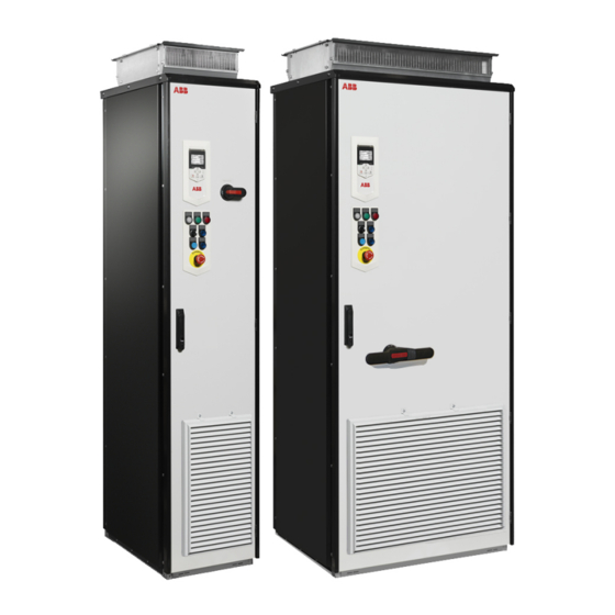
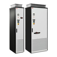
ABB ACS880-07LC Manuals
Manuals and User Guides for ABB ACS880-07LC. We have
11
ABB ACS880-07LC manuals available for free PDF download: Firmware Manual, Hardware Manual, User Manual, Manual
ABB ACS880-07LC Firmware Manual (604 pages)
primary control program
Brand:
ABB
| Category:
Servo Drives
| Size: 5 MB
Table of Contents
Table of Contents
5
Safety Instructions
11
Target Audience
11
Introduction to the Manual
11
Applicability
11
What this Chapter Contains
11
Contents of the Manual
12
Related Documents
12
Terms and Abbreviations
13
Cybersecurity Disclaimer
16
Using the Control Panel
17
Control Locations and Operating Modes
19
What this Chapter Contains
19
Local Control Vs. External Control
20
Local Control
20
External Control
21
Operating Modes of the Drive
22
DC Voltage Control Mode
23
Special Control Modes
23
Torque Control Mode
23
Speed Control Mode
23
Frequency Control Mode
23
Program Features
25
What this Chapter Contains
25
Drive Configuration and Programming
26
Programming Via Parameters
26
Adaptive Programming
27
Application Programming
27
Programmable Digital Inputs and Outputs
28
Control Interfaces
28
Programmable Analog Outputs
28
Programmable Analog Inputs
28
Programmable Relay Outputs
29
Programmable I/O Extensions
29
Fieldbus Control
30
Master/Follower Functionality
31
External Controller Interface
39
Control of a Supply Unit (LSU)
41
Motor Control
42
Direct Torque Control (DTC)
42
Reference Ramping
42
Constant Speeds/Frequencies
43
Critical Speeds/Frequencies
43
Speed Controller Autotune
44
Oscillation Damping
47
Resonance Frequency Elimination
48
Rush Control
48
Encoder Support
49
Jogging
55
Scalar Motor Control
58
Autophasing
59
Flux Braking
62
DC Magnetization
63
Hexagonal Motor Flux Pattern
65
Process PID Control
66
Application Macros
66
Application Control
66
Motor Potentiometer
69
Mechanical Brake Control
70
DC Voltage Control
75
Overvoltage Control
75
Undervoltage Control (Power Loss Ride-Through)
75
Voltage Control and Trip Limits
76
Brake Chopper
77
DC Voltage Control Mode
78
Safety and Protections
79
Emergency Stop
79
Motor Thermal Protection
80
Motor Overload Protection
83
Thermal Protection of Motor Cable
84
User Load Curve
84
Automatic Fault Resets
85
Other Programmable Protection Functions
86
Maintenance Timers and Counters
88
Fault and Warning Messages, Data Logging
88
Signal Supervision
88
Diagnostics
88
Energy Saving Calculators
89
Load Analyzer
89
Miscellaneous
91
User Parameter Sets
91
Parameter Checksum Calculation
91
User Lock
92
Reduced Run Function
93
Data Storage Parameters
93
Du/Dt Filter Support
94
Sine Filter Support
95
Router Mode for BCU Control Unit
95
Application Macros
97
What this Chapter Contains
97
General
97
Factory Macro
98
Default Parameter Settings for the Factory Macro
98
Default Control Connections for the Factory Macro
99
Hand/Auto Macro
100
Default Parameter Settings for the Hand/Auto Macro
100
Default Control Connections for the Hand/Auto Macro
101
PID Control Macro
102
Default Parameter Settings for the PID Control Macro
103
Default Control Connections for the PID Control Macro
104
Sensor Connection Examples for the PID Control Macro
105
Torque Control Macro
106
Default Parameter Settings for the Torque Control Macro
106
Default Control Connections for the Torque Control Macro
107
Sequential Control Macro
108
Operation Diagram
108
Selection of Constant Speeds
109
Default Parameter Settings for the Sequential Control Macro
109
Default Control Connections for the Sequential Control Macro
110
Fieldbus Control Macro
111
Parameters
113
What this Chapter Contains
113
Terms and Abbreviations
114
Advertisement
ABB ACS880-07LC Hardware Manual (294 pages)
Brand:
ABB
| Category:
DC Drives
| Size: 23 MB
Table of Contents
Table of Contents
5
Table of Contents
9
Safety Instructions
15
Contents of this Chapter
15
Use of Warnings and Notes
15
General Safety in Installation, Start-Up and Maintenance
16
Work on the Liquid Cooling System
18
Electrical Safety in Installation, Start-Up and Maintenance
19
Electrical Safety Precautions
19
Additional Instructions and Notes
20
Printed Circuit Boards
21
Grounding
21
General Safety in Operation
22
Additional Instructions for Permanent Magnet Motor Drives
23
Safety in Installation, Start-Up, Maintenance
23
Safety in Operation
23
Introduction to the Manual
25
Contents of this Chapter
25
Target Audience
25
Categorization by Frame Size and Option Code
25
Use of Component Designations
26
Quick Installation, Commissioning and Operation Flowchart
26
Terms and Abbreviations
27
Related Manuals
28
Operation Principle and Hardware Description
29
Contents of this Chapter
29
Operation Principle
29
Overview Circuit Diagram of the Drive
30
Overview Diagram of the Rectifier Bridge
31
12-Pulse Connection (Option +A004)
31
Layout Drawings
33
Ka Input Cubicle (Option +F274)
36
Overview of Power and Control Connections
37
Door Devices
38
Main Disconnecting Device [Q1]
39
Auxiliary Voltage Switch [Q21]
39
Grounding (Earthing) Switch [Q9], Optional
39
Other Devices on the Door
39
Control Panel
40
Control by PC Tools
40
Descriptions of Options
41
Degree of Protection
41
Definitions
41
Marine Construction (Option +C121)
41
UL Listed (Option +C129)
41
CSA Approved (Option +C134)
42
Plinth Height (Options +C164 and +C179)
42
Resistor Braking (Options +D150 and +D151)
42
D U /D T Filter (Option +E205)
42
Cabinet Heater with External Supply (Option +G300)
42
Cabinet Lighting (Option +G301)
42
Terminals for External Control Voltage (Option +G307)
42
Output for Motor Space Heater (Option +G313)
43
Supply Connection by Busbars (Option +G317)
43
Ready/Run/Fault Lights (Options +G327
43
Halogen-Free Wiring and Materials (Option +G330)
43
V-Meter with Selector Switch (Option +G334)
43
Wire Markings
43
Standard Wiring
43
Additional Wire Markings
44
Common Mode Filter Temperature Monitoring (Option +G453)
45
Bottom Cable Entry/Exit (Options +H350 and +H352)
45
Top Cable Entry/Exit (Options +H351 and +H353)
45
Cable Conduit Entry (Option +H358)
45
Common Motor Terminal Cubicle (Option +H359)
45
Common Output Terminals (Option +H366)
45
Roxtec Cable Entry (Option +H394)
46
Additional Terminal Block X504 (Option +L504)
47
Thermal Protection with PTC Relays (Options +L505, +2L505, +L513, +2L513, +L536, +L537)
47
L505, +2L505, +L513, +2L513
47
L536, +L537
48
Thermal Protection with Pt100 Relays (Options +Nl506, +Nl514)
48
Starter for Auxiliary Motor Fan (Options +M600
49
What the Option Contains
49
Description
49
Type Designation Label
50
Type Designation Key
50
Option Codes
51
Mechanical Installation
57
Contents of this Chapter
57
Examining the Installation Site
57
Necessary Tools
57
Examining the Delivery
58
Moving and Unpacking the Drive
58
Moving the Drive in Its Packaging
59
Lifting the Crate with a Forklift
59
Lifting the Crate with a Crane
60
Moving the Crate with a Forklift
61
Removing the Transport Package
61
Moving the Unpacked Drive Cabinet
62
Lifting the Cabinet with a Crane
62
Moving the Cabinet on Rollers
62
Moving the Cabinet on Its Back
63
Moving the Cabinet to Its Final Position
63
Attaching the Cabinet to the Floor and Wall or Roof
64
General Rules
64
Attaching the Cabinet (Non-Marine Units)
65
Alternative 1 - Clamping
65
Alternative 2 - Using the Holes Inside the Cabinet
66
Alternative 3 - Cabinets with Plinth Options +C164 and +C179
66
Attaching the Cabinet (Marine Units)
67
Joining Cabinet Sections Together
68
Miscellaneous
73
Cable Duct in the Floor below the Cabinet
73
Arc Welding
73
Lifting Lugs and Bars
74
Certificate of Conformity
74
Declarations of Conformity
74
Guidelines for Planning the Electrical Installation
75
Contents of this Chapter
75
Limitation of Liability
75
North America
75
Selecting the Supply Transformer
76
Basic Guidelines
76
Additional Notes
76
A Drive with a 12-Pulse Diode Supply Unit
76
Selecting the Supply Disconnecting Device
78
Examining the Compatibility of the Motor and Drive
78
Protecting the Motor Insulation and Bearings
78
Requirements Tables
79
Requirements for ABB Motors, P
79
Requirements for ABB Motors, P
80
Requirements for Non-ABB Motors, P
81
Requirements for Non-ABB Motors, P
82
Abbreviations
82
Availability of D U /D T Filter and Common Mode Filter by Drive Type
83
Additional Requirements for Explosion-Safe (EX) Motors
83
HX_ and am
83
Additional Requirements for Braking Applications
83
Additional Requirements for ABB High-Output and IP23 Motors
83
Additional Requirements for Non-ABB High-Output and IP23 Motors
83
Additional Data for Calculating the Rise Time and the Peak Line-To-Line Voltage
84
Additional Note for Sine Filters
85
Selecting the Power Cables
85
Power Cable Selection Procedure and Applicability Check
85
General Guidelines
86
Typical Power Cable Sizes
86
Power Cable Types
87
Preferred Power Cable Types
87
Alternate Power Cable Types
87
Not Allowed Power Cable Types
88
Power Cable Shield
88
Grounding Requirements
89
Additional Grounding Requirements - IEC
90
Additional Grounding Requirements - UL (NEC)
90
Selecting the Control Cables
90
Shielding
90
Signals in Separate Cables
91
Signals that Can be Run in the same Cable
91
Relay Cable
91
Control Panel to Drive Cable
91
PC Tool Cable
91
Routing the Cables
91
General Guidelines - IEC
91
The Motor Cable
92
Separate Control Cable Ducts
92
Situations and against Thermal Overload
93
Protecting the Input Cabling and the Drive Upon a Short-Circuit
93
Protecting the Motor and Motor Cable in Short-Circuits
93
Protecting the Drive and the Power Cables against Thermal Overload
93
Protecting the Motor against Thermal Overload
93
Protecting the Motor against Overload Without Thermal Model or Temperature Sensors
94
Protecting the Drive against Ground Faults
94
Residual Current Device Compatibility
94
Implementing the Emergency Stop Function
94
Implementing the Safe Torque off Function
95
Implementing the Prevention of Unexpected Start-Up Function
95
Implementing an ATEX-Certified Motor Thermal Protection
95
Implementing the Functions Provided by the FSO Safety Functions Module
96
Implementing the Power Loss Ride-Through Function
96
Implementing a Bypass Connection
97
Supplying Power for the Auxiliary Circuits
97
Using Power Factor Compensation Capacitors with the Drive
97
Using a Safety Switch between the Drive and the Motor
98
Implementing the Control of a Contactor between Drive and Motor
98
Protecting the Contacts of Relay Outputs
99
Implementing a Motor Temperature Sensor Connection
99
Connecting a Motor Temperature Sensor to the Drive through an Option Module
100
Electrical Installation
103
Contents of this Chapter
103
Measuring the Insulation
103
Measuring the Insulation Resistance of the Drive
103
Measuring the Insulation Resistance of the Motor and Motor Cable
103
Measuring the Insulation Resistance of the Input Power Cable
104
Connecting the Control Cables
105
Control Cable Connection Procedure
105
Grounding the Outer Shields of the Control Cables 360° at the Cabinet Entry
105
Routing the Control Cables Inside the Cabinet
107
Connecting Control Cabling
107
Connecting the Motor Cables (Units Without Common Motor Terminal Cubicle)
108
Motor Connection Diagram (Without Option +H366)
108
Motor Connection Diagram (with Option +H366)
109
Procedure
110
Removing the Shrouds
111
Connecting the Cables
111
Installing the Shrouds
113
Connecting the Cables at the Motor End
114
Connecting the Motor Cables (Units with Common Motor Terminal Cubicle)
114
Output Busbars
114
Connection Diagram
114
Procedure
115
Removing Shrouds
115
Connecting the Cables
115
Installing Shrouds
116
Connecting the Cables at the Motor End
117
Connecting the Input Power Cables
117
Connection Diagram, 6-Pulse Units
117
Connection Diagram, 12-Pulse Units
118
Layout of the Input Cable Connection Terminals and Cable Entries
118
Connection Procedure
118
Removing Shrouds
118
Connecting the Cables
119
Installing Shrouds
121
Connecting Input Power Cables - Cable Entry in 100 Ka Input Cubicle (Option +F274)
122
Connection Diagram
122
Connection Procedure
122
Removing Shrouds and Beams in Front of the Input Cable Terminals
122
Connecting the Cables
123
Replacing Shrouds and Beams in Front of Input Power Cable Terminals
125
Connecting an External Brake Resistor Assembly
126
Use of Fasteners in Cable Lug Connections
127
Connecting a PC
128
Panel Bus (Control of Several Units from One Control Panel)
128
Installing Option Modules
131
Installation of I/O Extension and Fieldbus Adapter Modules on UCU Control Unit
131
Mechanical Installation of I/O Extension, Fieldbus Adapter and Pulse Encoder
131
Interface Modules on BCU Control Unit
131
Installation of an FSO Safety Functions Module Onto BCU Control Unit
132
Wiring of Option Modules
133
Control Unit (UCU)
135
Contents of this Chapter
135
General
135
Layout
135
Default I/O Diagram of the Supply Control Unit
139
Default I/O Diagram of the Inverter Control Unit
141
Additional Information on the Connections
146
Connecting Motor Temperature Sensors to the Drive
146
Power Supply for the Control Unit (XPOW)
146
Digital Interlock (DIIL)
146
Control Panel Connection (XPAN)
146
The XD2D Connector
146
Safe Torque off (XSTO, XSTO OUT)
147
Safety Functions Module Connection (XFSO)
147
Microsdhc Memory Card Slot
147
Connector Data
147
Ground Isolation Diagram
150
ABB ACS880-07LC Hardware Manual (222 pages)
INDUSTRIAL DRIVES
Brand:
ABB
| Category:
DC Drives
| Size: 15 MB
Table of Contents
Table of Contents
5
Table of Contents
9
Safety Instructions
13
Contents of this Chapter
13
Use of Warnings and Notes
13
General Safety in Installation, Start-Up and Maintenance
14
Work on the Liquid Cooling System
16
Electrical Safety in Installation, Start-Up and Maintenance
16
Electrical Safety Precautions
16
Additional Instructions and Notes
18
Optical Components
18
Printed Circuit Boards
18
Grounding
19
General Safety in Operation
20
Additional Instructions for Permanent Magnet Motor Drives
20
Safety in Installation, Start-Up, Maintenance
20
Safety in Operation
21
Introduction to the Manual
23
Contents of this Chapter
23
Target Audience
23
Categorization by Frame Size and Option Code
23
Use of Component Designations
24
Quick Installation, Commissioning and Operation Flowchart
24
Terms and Abbreviations
25
Related Manuals
25
Operation Principle and Hardware Description
27
Contents of this Chapter
27
Operation Principle
27
Overview Circuit Diagram of the Drive
28
Overview Diagram of the Rectifier Bridge
29
12-Pulse Connection (Option +A004)
29
Layout Drawings
31
Overview of Power and Control Connections
34
Door Switches and Lights
35
Main Disconnecting Device [Q1]
36
Auxiliary Voltage Switch [Q21]
36
Grounding (Earthing) Switch [Q9], Optional
36
Other Devices on the Door
36
Control Panel
36
Control by PC Tools
37
Descriptions of Options
38
Degree of Protection
38
Definitions
38
Marine Construction (Option +C121)
38
Plinth Height (Options +C164 and +C179)
38
Resistor Braking (Options +D150 and +D151)
38
Du/Dt Filter (Option +E205)
38
Cabinet Heater with External Supply (Option +G300)
39
Cabinet Lighting (Option +G301)
39
Terminals for External Control Voltage (Option +G307)
39
Halogen-Free Wiring and Materials (Option +G330)
39
Wire Markings
39
Standard Wiring
39
Additional Wire Markings
40
Thermal Protection with PTC Relays (Options +L505, +2L505, +L513, +2L513, +L536, +L537)
41
L505, +2L505, +L513, +2L513
41
L536, +L537
41
Thermal Protection with Pt100 Relays (Options +Nl506, +Nl514)
42
Type Designation Label
43
Type Designation Key
43
Option Codes
44
Mechanical Installation
47
Contents of this Chapter
47
Examining the Installation Site
47
Necessary Tools
47
Examining the Delivery
48
Moving and Unpacking the Drive
49
Removing the Transport Package
49
Moving the Unpacked Drive Cabinet
50
Lifting the Cabinet with a Crane
50
Moving the Cabinet on Rollers
51
Moving the Cabinet on Its Back
51
Final Placement of the Cabinet
52
Attaching the Cabinet to the Floor and Wall or Roof
53
General Rules
53
Attaching the Cabinet (Non-Marine Units)
54
Alternative 1 - Clamping
54
Alternative 2 - Using the Holes Inside the Cabinet
55
Attaching the Cabinet (Marine Units)
56
Joining Cabinet Sections Together
57
Miscellaneous
61
Cable Duct in the Floor below the Cabinet
61
Arc Welding
61
Lifting Lugs and Bars
62
Certificate of Conformity
62
Declaration of Conformity
62
Guidelines for Planning the Electrical Installation
65
Contents of this Chapter
65
Limitation of Liability
65
Selecting the Supply Disconnecting Device
65
Selecting the Main Contactor or Breaker
65
Examining the Compatibility of the Motor and Drive
66
Protecting the Motor Insulation and Bearings
66
Requirements Table
66
Availability of Du/Dt Filter and Common Mode Filter by Drive Type
69
Additional Requirements for Explosion-Safe (EX) Motors
69
And am
69
Additional Requirements for ABB High-Output and IP23 Motors
69
Additional Requirements for Non-ABB High-Output and IP23 Motors
69
Additional Note for Sine Filters
70
Selecting the Power Cables
70
General Guidelines
70
Typical Power Cable Sizes
71
Power Cable Types
71
Preferred Power Cable Types
71
Alternate Power Cable Types
72
Not Allowed Power Cable Types
73
Power Cable Shield
73
Selecting the Control Cables
74
Shielding
74
Signals in Separate Cables
74
Signals that Can be Run in the same Cable
74
Relay Cable
74
Control Panel to Drive Cable
74
PC Tool Cable
75
Routing the Cables
75
General Guidelines - IEC
75
Continuous Motor Cable Shield/Conduit or Enclosure for Equipment on the Motor Cable
76
Separate Control Cable Ducts
76
Implementing Short-Circuit and Thermal Overload Protection
76
Protecting the Input Cabling and the Drive Upon a Short-Circuit
76
Protecting the Motor and Motor Cable in Short-Circuits
76
Protecting the Drive and the Power Cables against Thermal Overload
76
Protecting the Motor against Thermal Overload
77
Protecting the Drive against Ground Faults
77
Residual Current Device Compatibility
77
Implementing the Emergency Stop Function
77
Implementing the Safe Torque off Function
77
Implementing the Power Loss Ride-Through Function
78
Implementing a Bypass Connection
78
Supplying Power for the Auxiliary Circuits
78
Using Power Factor Compensation Capacitors with the Drive
79
Using a Safety Switch between the Drive and the Motor
79
Implementing the Control of a Contactor between Drive and Motor
79
Protecting the Contacts of Relay Outputs
79
Implementing a Motor Temperature Sensor Connection
80
Connecting Motor Temperature Sensor to the Drive Via an Option Module
81
Electrical Installation
83
Contents of this Chapter
83
Warnings
83
Measuring the Insulation
83
Measuring the Insulation of the Drive
83
Measuring the Insulation of the Motor and Motor Cable
84
Connecting the Control Cables
85
Control Cable Connection Procedure
85
Grounding the Outer Shields of the Control Cables at the Cabinet Entry
85
Routing the Control Cables Inside the Cabinet
87
Connecting Control Cabling
87
Connecting the Motor Cables (Units Without Common Motor Terminal Cubicle)
89
Motor Connection Diagram (Without Option +H366)
89
Procedure
90
Connecting the Motor Cables (Units with Common Motor Terminal Cubicle)
92
Output Busbars
92
Connection Diagram
92
Procedure
92
Connecting an External Brake Resistor Assembly
93
Connecting the Input Power Cables
94
Connection Diagram, 6-Pulse Units
94
Connection Diagram, 12-Pulse Units
94
Layout of the Input Cable Connection Terminals and Cable Entries
95
Connection Procedure
95
Connecting a PC
98
Panel Bus (Control of Several Units from One Control Panel)
98
Installing Option Modules
101
Mechanical Installation of I/O Extension, Fieldbus Adapter and Pulse Encoder Interface Modules
101
Installation of an FSO-XX Safety Functions Module Onto BCU
101
Wiring of Option Modules
103
Control Units of the Drive
105
Contents of this Chapter
105
BCU-X2 Layout
106
Default I/O Diagram of the Supply Control Unit
108
Default I/O Diagram of the Inverter Control Unit (A41)
111
Additional Information on the Connections
112
External Power Supply for the Control Unit (XPOW)
112
DI6 as a PTC Sensor Input
112
AI1 or AI2 as a Pt100, Pt1000, PTC or KTY84 Sensor Input
113
DIIL Input
113
The XD2D Connector
113
Advertisement
ABB ACS880-07LC User Manual (74 pages)
Brand:
ABB
| Category:
DC Drives
| Size: 1 MB
Table of Contents
Table of Contents
5
1 Safety Instructions
9
Contents of this Chapter
9
Use of Warnings and Notes
9
Instructions for Functional Safety Circuits
9
Electrical Safety Precautions
10
2 Introduction to the Manual
13
Contents of this Chapter
13
Applicability
13
Target Audience
13
Exclusion of Liability
14
Quick Reference Guide for Taking a Safety Function into Use
14
Related Manuals
14
Terms and Abbreviations
16
3 Option Description
17
Contents of this Chapter
17
Overview
17
Summary of Wirings and Settings
18
Operation Principle
20
Time Schemes with a Speed Estimate (no Safety Encoder)
21
Emergency Stop, Stop Category 0
21
Emergency Stop, Stop Category 1 with Time Monitoring
22
Emergency Stop, Stop Category 1 with Ramp Monitoring
24
Time Schemes with a Safety Encoder
27
Emergency Stop, Stop Category 0
27
Emergency Stop, Stop Category 1 with Time Monitoring
28
Emergency Stop, Stop Category 1 with Ramp Monitoring
30
Operation Principle Diagrams
32
ACS880-07 Drives, Frames R6 to R11 and ACS880-17/-37 Drives, Frame R8
32
ACS880-07/07LC Drives, Frames N×Dxt + N×R8I
33
ACS880-17/17LC/37/37LC Drives, Frames N×R8I + N×R8I
35
ACS880-17/37 Drives, Frame R11
37
Fault Reaction Function
38
FSO Module
38
Resetting the FSO Module
38
FSE-31 Module
39
Safety Encoder
39
STO Function in the Drive
39
4 Electrical Installation
41
Contents of this Chapter
41
Wiring
41
Customer-Installed Main Breaker in ACS880-07LC/17LC/37LC Drives
42
5 Parameter Settings
43
Contents of this Chapter
43
Competence
43
FSO Module Parameter Settings
43
General Parameters
44
Parameters for the STO Function
46
Parameters for the SSE Function
48
I/O Parameters
49
Parameters for Emergency Stop, Stop Category 0
50
Parameters for Emergency Stop, Stop Category 1
51
Changing the Stop Category from 0 to 1
53
FSE-31 Module and Safety Pulse Encoder Related Parameters
54
Drive Parameter Settings
55
Additional Parameter Settings for ACS880-07/07LC Drives, Frames N×Dxt + N×R8I and ACS880-17/17LC/37/37LC Drives, Frames N×R8I + N×R8I
55
Additional Parameter Settings for ACS880-17/37, Frames R8 and R11
55
Safety Pulse Encoder Parameters
56
SS1 Ramp Parameters
56
ABB ACS880-07LC User Manual (68 pages)
Emergency stop, configurable stop category 0 or 1б option +Q979
Brand:
ABB
| Category:
Servo Drives
| Size: 1 MB
Table of Contents
Table of Contents
5
Safety Instructions
9
Contents of this Chapter
9
Safety Messages
9
Instructions for Functional Safety Circuits
10
Electrical Safety Precautions
11
Introduction to the Manual
13
Contents of this Chapter
13
Applicability
13
Target Audience
14
Exclusion of Liability
14
Quick Reference Guide for Taking a Safety Function into Use
14
Related Manuals
14
Terms and Abbreviations
16
Option Description
17
Contents of this Chapter
17
Overview
17
Summary of Wirings and Settings
18
Operation Principle
19
Time Schemes with a Speed Estimate (no Safety Encoder)
20
Emergency Stop, Stop Category 0
20
Emergency Stop, Stop Category 1 with Time Monitoring
21
Emergency Stop, Stop Category 1 with Ramp Monitoring
23
Time Schemes with a Safety Encoder
25
Emergency Stop, Stop Category 0
25
Emergency Stop, Stop Category 1 with Time Monitoring
26
Emergency Stop, Stop Category 1 with Ramp Monitoring
28
Operation Principle Diagrams
29
Fault Reaction Function
31
FSO Module
31
Resetting the FSO Module
31
FSE-31 Module and Safety Encoder
31
Drive STO Function
32
Electrical Installation
33
Contents of this Chapter
33
Wiring
33
Parameter Settings
35
Contents of this Chapter
35
Competence
35
FSO Module Parameter Settings
35
General Parameters
36
Parameters for the STO Function
38
Parameters for the SSE Function
40
I/O Parameters
40
Parameters for Emergency Stop, Stop Category 0
41
Parameters for Emergency Stop, Stop Category 1
41
Changing the Stop Category from 0 to 1
44
FSE-31 Module and Safety Encoder Related Parameters
44
Drive Parameter Settings
46
Use of the Safety Function
49
ABB ACS880-07LC Manual (66 pages)
Safely-limited speed with the encoder interface (option +Q965)
Brand:
ABB
| Category:
DC Drives
| Size: 1 MB
Table of Contents
Table of Contents
5
1 Safety Instructions
7
Contents of this Chapter
7
Use of Warnings and Notes
7
Instructions for Functional Safety Circuits
8
Electrical Safety Precautions
9
2 Introduction to the Manual
11
Contents of this Chapter
11
Applicability
11
Target Audience
11
Exclusion of Liability
12
Quick Reference Guide for Taking a Safety Function into Use
12
Related Manuals
12
Terms and Abbreviations
14
3 Option Description
15
Contents of this Chapter
15
Overview
15
Summary of Wirings and Settings
16
Operation Principle
17
SLS Function
17
SLS with Speed below the Monitored Speed
18
SLS with Speed above the Monitored Speed - Time Monitoring
20
SLS with Speed above the Monitored Speed - Ramp Monitoring
22
SLS Reaction When Modulation Is Lost During Deceleration Ramp
23
SMS Function
28
SSM Function
29
Drive Modulation Loss When Encoder Feedback Is Used
30
Operation Principle Diagram
31
Fault Reaction Function
32
FSO Module
32
Resetting the FSO Module
32
FSE-31 Module and Safety Encoder
32
Drive STO Function
33
4 Electrical Installation
35
Contents of this Chapter
35
Wiring
35
SLS Function
36
SMS Function
36
SSM Function
36
5 Parameter Settings
37
Contents of this Chapter
37
Competence
37
FSO Module Parameter Settings
37
General Parameters
38
Parameters for the STO Function
39
Parameters for the SSE Function
40
Parameters for the SLS Function
43
Parameters for the SMS Function
46
Parameters for the SSM Function
46
FSE-31 Module and Safety Pulse Encoder Related Parameters
47
Drive Parameter Settings
49
Ramp Parameters
49
ABB ACS880-07LC User Manual (58 pages)
Emergency stop, configurable stop category 0 or 1 (option +Q979)
Brand:
ABB
| Category:
DC Drives
| Size: 1 MB
Table of Contents
Table of Contents
5
1 Safety Instructions
7
Contents of this Chapter
7
Use of Warnings and Notes
7
Instructions for Functional Safety Circuits
8
Electrical Safety Precautions
9
2 Introduction to the Manual
11
Contents of this Chapter
11
Applicability
11
Target Audience
11
Exclusion of Liability
12
Quick Reference Guide for Taking a Safety Function into Use
12
Related Manuals
12
Terms and Abbreviations
14
3 Option Description
15
Contents of this Chapter
15
Overview
15
Summary of Wirings and Settings
16
Operation Principle
17
Time Schemes with a Speed Estimate (no Safety Encoder)
18
Emergency Stop, Stop Category 0
18
Emergency Stop, Stop Category 1 with Time Monitoring
19
Emergency Stop, Stop Category 1 with Ramp Monitoring
21
Time Schemes with a Safety Encoder
23
Emergency Stop, Stop Category 0
23
Emergency Stop, Stop Category 1 with Time Monitoring
24
Emergency Stop, Stop Category 1 with Ramp Monitoring
26
Operation Principle Diagrams
28
Fault Reaction Function
29
FSO Module
29
Resetting the FSO Module
30
FSE-31 Module and Safety Encoder
30
Drive STO Function
30
4 Electrical Installation
31
Contents of this Chapter
31
Wiring
31
5 Parameter Settings
33
Contents of this Chapter
33
Competence
33
FSO Module Parameter Settings
33
General Parameters
34
Parameters for the STO Function
36
Parameters for the SSE Function
38
I/O Parameters
38
Parameters for Emergency Stop, Stop Category 0
39
Parameters for Emergency Stop, Stop Category 1
39
Changing the Stop Category from 0 to 1
41
FSE-31 Module and Safety Pulse Encoder Related Parameters
42
Drive Parameter Settings
44
ABB ACS880-07LC User Manual (58 pages)
Emergency stop, stop category 1 (option +Q952) for
Brand:
ABB
| Category:
DC Drives
| Size: 1 MB
Table of Contents
Table of Contents
5
1 Safety Instructions
9
Contents of this Chapter
9
Use of Warnings and Notes
9
Instructions for Functional Safety Circuits
9
Electrical Safety Precautions
10
2 Introduction to the Manual
13
Contents of this Chapter
13
Applicability
13
Target Audience
13
Exclusion of Liability
13
Quick Reference Guide for Taking a Safety Function into Use
14
Related Manuals
14
Terms and Abbreviations
15
3 Option Description
17
Contents of this Chapter
17
Overview
17
Operation Principle
18
ACS880-07 Drives, Frames R6 to R11 and ACS880-17/-37 Drives, Frame R8
18
ACS880-17/37 Drives, Frame R11
20
ACS880-07/07LC Drives, Frames N×Dxt + N×R8I
22
ACS880-17/37 and -17LC/37LC Drives, Frames N×R8I + N×R8I
24
Fault Reaction Function
26
Hardware Settings
26
4 Electrical Installation
27
Contents of this Chapter
27
Wiring
27
Customer-Installed Main Breaker in ACS880-07LC/17LC/37LC Drives
28
5 Parameter Settings
29
Contents of this Chapter
29
Drive Parameter Settings
29
Additional Parameter Settings for ACS880-07/07LC Drives, Frames N×Dxt + N×R8I and ACS880-17/17LC/37/37LC Drives, Frames N×R8I + N×R8I
30
Additional Parameter Settings for ACS880-17/37, Frames R8 and R11
31
6 Use of the Safety Function
33
Contents of this Chapter
33
Activating the Safety Function
33
Resetting the Safety Function
33
7 Start-Up and Acceptance Test
35
Contents of this Chapter
35
Validation of the Safety Functions
35
Competence
35
Validation Procedure
35
Acceptance Test Reports
36
Start-Up and Acceptance Test
36
8 Fault Tracing
39
Contents of this Chapter
39
ACS880-07 Drives, Frames R6 to R11 and ACS880-17/37 Drives, Frames R8 and R11
40
Reporting Problems and Failures Related to Safety Functions
40
9 Maintenance
41
Contents of this Chapter
41
Safety Circuit Maintenance
41
Proof Test Interval
42
Competence
42
Residual Risk
42
Intentional Misuse
42
Decommissioning
42
ABB ACS880-07LC User Manual (42 pages)
Brand:
ABB
| Category:
DC Drives
| Size: 1 MB
Table of Contents
Table of Contents
5
1 Safety Instructions
7
Contents of this Chapter
7
Use of Warnings and Notes
7
Instructions for Functional Safety Circuits
8
Electrical Safety Precautions
9
2 Introduction to the Manual
11
Contents of this Chapter
11
Applicability
11
Target Audience
11
Exclusion of Liability
12
Quick Reference Guide for Taking a Safety Function into Use
12
Related Manuals
12
Terms and Abbreviations
14
3 Option Description
15
Contents of this Chapter
15
Overview
15
Summary of Wirings and Settings
16
Operation Principle
17
Time Scheme
17
Operation Principle Diagram
18
Fault Reaction Function
19
FSO Module
19
Resetting the FSO Module
19
Drive STO Function
19
4 Electrical Installation
21
Contents of this Chapter
21
Wiring
21
5 Parameter Settings
23
Contents of this Chapter
23
Competence
23
FSO Module Parameter Settings
23
General Parameters
24
Parameters for the STO Function
25
Parameters for the SSE Function
25
Parameters for the POUS Function
25
Drive Parameter Settings
27
6 Use of the Safety Function
29
Contents of this Chapter
29
Activating the Safety Function
29
Resetting the Safety Function
29
7 Start-Up and Validation Test
31
Contents of this Chapter
31
Validation of the Safety Functions
31
Competence
31
Validation Procedure
31
Validation Test Reports
32
Start-Up and Validation Test
32
8 Maintenance
35
Contents of this Chapter
35
Safety Circuit Maintenance
35
Proof Test Interval
35
Competence
36
Residual Risk
36
Intentional Misuse
36
Decommissioning
36
ABB ACS880-07LC User Manual (42 pages)
Emergency stop, stop category 1 (option+Q964) for drives
Brand:
ABB
| Category:
Industrial Equipment
| Size: 0 MB
Table of Contents
Table of Contents
5
Safety Instructions
7
Contents of this Chapter
7
Safety Messages
7
Instructions for Functional Safety Circuits
8
Electrical Safety Precautions
9
Introduction to the Manual
11
Contents of this Chapter
11
Applicability
11
Target Audience
11
Exclusion of Liability
12
Quick Reference Guide for Taking a Safety Function into Use
12
Terms and Abbreviations
12
Option Description
15
Contents of this Chapter
15
Overview
15
Operation Principle
16
Fault Reaction Function
17
Electrical Installation
19
Contents of this Chapter
19
Wiring
19
Hardware Settings
20
Parameter Settings
21
Contents of this Chapter
21
Drive Parameter Settings
21
Supply Unit Parameter Settings
22
Use of the Safety Function
23
Contents of this Chapter
23
Activating the Safety Function
23
Resetting the Safety Function
23
Start-Up and Validation Test
25
Contents of this Chapter
25
Validation of the Safety Functions
25
Competence
25
Validation Procedure
25
Validation Test Reports
26
Start-Up and Validation Test
26
Fault Tracing
29
Contents of this Chapter
29
Emergency Stop Safety Relay
29
Extension Safety Relay
30
STO Circuit Connections
30
Other
31
Reporting Problems and Failures Related to Safety Functions
31
Maintenance
33
Contents of this Chapter
33
Safety Circuit Maintenance
33
Proof Test Interval
33
Functional Safety Components
34
Competence
34
ABB ACS880-07LC User Manual (36 pages)
Emergency stop, stop category 1 (option+Q964) for
Brand:
ABB
| Category:
DC Drives
| Size: 1 MB
Table of Contents
Table of Contents
5
1 Safety Instructions
7
Contents of this Chapter
7
Use of Warnings and Notes
7
Instructions for Functional Safety Circuits
8
Electrical Safety Precautions
9
2 Introduction to the Manual
11
Contents of this Chapter
11
Applicability
11
Target Audience
11
Exclusion of Liability
11
Quick Reference Guide for Taking a Safety Function into Use
12
Terms and Abbreviations
12
3 Option Description
13
Contents of this Chapter
13
Overview
13
Operation Principle
14
Fault Reaction Function
15
Hardware Settings
16
4 Electrical Installation
17
Contents of this Chapter
17
Wiring
17
5 Parameter Settings
19
Contents of this Chapter
19
Drive Parameter Settings
19
Additional Parameter Settings for ACS880-07/07LC Drives, Frames N×Dxt + N×R8I and ACS880-17/17LC/37/37LC Drives, Frames N×R8I + N×R8I
20
6 Use of the Safety Function
21
Contents of this Chapter
21
Activating the Safety Function
21
Resetting the Safety Function
22
7 Start-Up and Validation Test
23
Contents of this Chapter
23
Validation of the Safety Functions
23
Competence
23
Validation Procedure
23
Validation Test Reports
24
Start-Up and Validation Test
24
8 Fault Tracing
27
Contents of this Chapter
27
Reporting Problems and Failures Related to Safety Functions
28
9 Maintenance
29
Contents of this Chapter
29
Safety Circuit Maintenance
29
Proof Test Interval
29
Competence
30
Residual Risk
30
Intentional Misuse
30
Decommissioning
30
10 Technical Data
31
Contents of this Chapter
31
Safety Data
31
Safety Data Values
31
Safety Component Types
32
Safety Block Diagrams
32
Relevant Failure Modes
32
Fault Exclusions
32
Operation Delays
33
Ambient Conditions
33
ACS880-07 Drives, Frames R6
33
Related Standards and Directives
33
Compliance with the European Machinery Directive
34
Further Information
35
Advertisement
Related Products
ABB ACS880-07LC-0850A-7
ABB ACS880-07LC-1660A-7
ABB ACS880-07LC-1660A-7+A004
ABB ACS880-07LC-3260A-7
ABB ACS880-07XT-1610A-3
ABB ACS880-07-0302A-5
ABB ACS880-07-0361A-5
ABB ACS880-07-0820A-5
ABB ACS880-07-0098A-7
ABB ACS880-07-0430A-7
ABB Categories
Industrial Equipment
Controller
Measuring Instruments
Battery Charger
DC Drives
More ABB Manuals
Login
Sign In
OR
Sign in with Facebook
Sign in with Google
Upload manual
Upload from disk
Upload from URL