Sign In
Upload
Manuals
Brands
ABB Manuals
Industrial Equipment
AC500 V2
ABB AC500 V2 Manuals
Manuals and User Guides for ABB AC500 V2. We have
3
ABB AC500 V2 manuals available for free PDF download: Hardware Manual, Getting Started
ABB AC500 V2 Hardware Manual (1546 pages)
PLC Automation
Brand:
ABB
| Category:
Controller
| Size: 31 MB
Table of Contents
Table of Contents
2
Device Specifications
4
Status Leds, Display and Control Elements
4
Terminal Bases (AC500 Standard)
4
Tb51X-Tb54X
4
TF501-CMS and TF521-CMS - Function Module Terminal Bases
14
Electrical Connection
15
Processor Modules
21
AC500-Eco
21
Electrical Connection
51
AC500 (Standard)
65
Other Interfaces
68
AC31 Adapters
91
Electromagnetic Compatibility
94
Available Versions
111
Electrical Connection
113
Measuring Ranges
123
Protective Functions
125
Digital Inputs/Outputs
136
Electrical Connection
149
Electrical Connection
164
Electrical Connection
180
Mounting Information
195
Electrical Connection
199
Mounting Information
209
Electrical Connection
213
Mounting Information
225
Electrical Connection
229
Connector / Block
231
Communication Modules (AC500 Standard)
249
Overview
249
Compatibility of Communication Modules and Communication Interface Modules
253
Rcom / Rcom
255
Serial
260
Electrical Connection
260
Canopen
264
Bus Terminating Resistors
267
Ethercat
277
Ethernet
281
State Description
283
Profibus
285
Bus Terminating Resistors
295
Profinet
295
State Description
298
Terminal Units (AC500 Standard)
306
TU507-ETH and TU508-ETH for Ethernet Communication Interface Modules
306
TU509 and TU510 for Communication Interface Modules
310
TU515, TU516, TU541 and TU542 for I/O Modules
314
Extreme Conditions
317
TU517 and TU518 for Communication Interface Modules
320
TU520-ETH for PROFINET Communication Interface Modules
322
TU531 and TU532 for I/O Modules
325
TU551-CS31 and TU552-CS31 for CS31 Communication Interface Modules
332
I/O Modules
335
Digital I/O Modules
335
Electrical Connection
337
Electrical Connection
438
Electrical Connection
463
Electrical Connection
488
Electrical Connection
501
Electrical Connection
550
Analog I/O Modules
560
Electrical Connection
620
Electrical Connection
644
Electrical Connection
664
Electrical Connection
696
Electrical Connection
758
Electrical Connection
792
Function Modules
823
Electrical Connection
825
Electrical Connection
843
Electrical Connection
865
Device Module
874
Intended Purpose
892
Electrical Connection
895
Bus Terminating Resistors
896
Output Characteristics
932
Electrical Connection
932
Bus Terminating Resistors
933
Electrical Connection
952
Electrical Connection
972
Intended Purpose
1003
Electrical Connection
1004
Intended Purpose
1020
Electrical Connection
1021
Intended Purpose
1052
Electrical Connection
1053
Electrical Connection
1071
Electrical Connection
1111
Electrical Connection
1136
Intended Purpose
1173
Electrical Connection
1174
Connection of the Digital Inputs
1180
Electrical Connection
1200
Electrical Connection
1239
Electrical Connection
1262
Electrical Connection
1277
Handling Instruction
1294
Electrical Connection
1295
Intended Purpose
1303
Electrical Connection
1326
Introduction and Basics
1329
Intended Use
1329
PC System Requirements
1329
Content of the Installation Package
1329
Installation
1330
Installation Steps
1330
Pre-Installation Routine
1330
Communication
1332
Virtual Communication Port Configuration
1332
Automation Builder Communication
1334
3ADR020159M0201, 1, En_Us
1334
Connection: Interface
1341
Handling Instructions
1359
Electrical Connection
1365
Intended Purpose
1367
Usb Driver Installation
1369
Introduction and Basics
1371
Intended Use
1371
PC System Requirements
1371
Content of the Installation Package
1371
Installation
1372
Installation Steps
1372
Pre-Installation Routine
1372
Communication
1374
Virtual Communication Port Configuration
1374
Uninstallation / Update
1378
Handling Instructions
1386
System Assembly, Construction and Connection
1390
Introduction
1390
Regulations
1390
Safety Instructions
1391
Cleaning Instruction
1392
Information on Batteries
1393
Environment Considerations
1394
Environment and Enclosure Information
1394
Overall Information (Valid for Complete AC500 Product Family)
1394
Serial I/O Bus
1394
Mechanical Encoding
1397
Earthing Concept (Block Diagrams)
1400
Digital I/O Interface
1401
EMC-Conforming Assembly and Construction
1402
Equipotential Bonding
1405
Power Consumption of an Entire Station
1406
Decommissioning
1409
Recycling and Disposal
1409
AC500-Eco
1409
System Data AC500-Eco
1409
Environmental Conditions
1409
Mechanical Dimensions
1413
Mounting and Demounting
1416
Connection and Wiring
1425
Handling of Accessories
1439
Intended Purpose
1447
AC500 (Standard)
1472
System Data AC500
1472
Electromagnetic Compatibility
1475
Mechanical Dimensions
1477
Mounting and Demounting
1485
Mounting with Screws
1491
Connection and Wiring
1496
Cable Length Restrictions
1513
Straight-Through Cable
1515
Handling of Accessories
1518
Ac500-XC
1541
System Data AC500-XC
1541
Environmental Conditions
1541
Ac500-S
1545
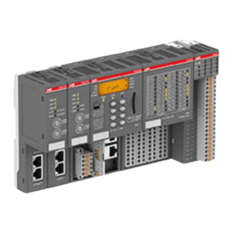
ABB AC500 V2 Hardware Manual (1319 pages)
PLC System Assembly and Device Specifications
Brand:
ABB
| Category:
Controller
| Size: 52 MB
Table of Contents
Table of Contents
2
Device Specifications
4
Terminal Bases (AC500 Standard)
4
Tb51X-Tb54X
4
TF501-CMS and TF521-CMS - Function Module Terminal Bases
13
Processor Modules
20
AC500-Eco
21
AC500 (Standard)
65
Buttons and Switches
88
Communication Modules (AC500 Standard)
92
Overview
92
CM574-RCOM for RCOM/RCOM
95
CM574-RS with 2 Serial Interfaces
100
Canopen
104
Bus Terminating Resistors
106
Ethercat
116
Ethernet
120
State Description
122
Profibus
124
Bus Terminating Resistors
134
Profinet
134
State Description
137
Terminal Units (AC500 Standard)
145
TU507-ETH and TU508-ETH for Ethernet Communication Interface Modules
145
TU509 and TU510 for Communication Interface Modules
149
TU515, TU516, TU541 and TU542 for I/O Modules
153
Extreme Conditions
156
TU517 and TU518 for Communication Interface Modules
158
TU520-ETH for PROFINET Communication Interface Modules
161
TU531 and TU532 for I/O Modules
164
TU551-CS31 and TU552-CS31 for CS31 Communication Interface Modules
170
I/O Modules
173
Digital I/O Modules
173
Bus Module
247
Analog I/O Modules
397
Digital/Analog I/O Modules
571
Function Modules
636
S500-Eco
636
S500
654
Device Module
687
Communication Interface Modules (S500)
700
Canopen
700
Intended Purpose
703
Bus Terminating Resistors
707
Bus Terminating Resistors
743
Cs31
762
Intended Purpose
814
Ethercat
830
Intended Purpose
831
Intended Purpose
863
Modbus
880
Profibus
945
Intended Purpose
984
Connection of the Digital Inputs
991
Profinet
1007
Accessories
1106
AC500-Eco
1106
Handling Instruction
1106
Electrical Connection
1107
Intended Purpose
1107
Electrical Connection
1130
Introduction and Basics
1133
Intended Use
1133
PC System Requirements
1133
Content of the Installation Package
1133
Installation
1134
Installation Steps
1134
Pre-Installation Routine
1134
Communication
1136
Virtual Communication Port Configuration
1136
Automation Builder Communication
1138
3ADR020159M0201, 1, En_Us
1138
Uninstallation / Update
1140
Connection: Interface
1145
AC500 (Standard)
1147
Handling Instructions
1150
Intended Purpose
1158
Electrical Connection
1161
Usb Driver Installation
1165
S500-Eco
1166
S500
1168
Handling Instructions
1172
System Assembly, Construction and Connection
1176
Introduction
1176
Regulations
1176
Safety Instructions
1177
Cleaning Instruction
1178
Information on Batteries
1179
Environment Considerations
1180
Environment and Enclosure Information
1180
Overall Information (Valid for Complete AC500 Product Family)
1180
Digital I/O Interface
1187
Equipotential Bonding
1190
Recycling and Disposal
1194
Environmental Conditions
1194
Electromagnetic Compatibility
1197
Mechanical Dimensions
1198
Mounting and Demounting
1201
Connection and Wiring
1210
Straight-Through Cable
1222
Intended Purpose
1227
Mounting on DIN Rail
1270
Mounting with Screws
1271
Cable Length Restrictions
1293
Environmental Conditions
1313
ABB AC500 V2 Getting Started (66 pages)
Brand:
ABB
| Category:
Industrial Equipment
| Size: 3 MB
Table of Contents
Table of Contents
2
Getting Started with Example Projects
3
Introduction
3
Safety Instructions
3
Engineering Software Automation Builder
6
Installing Automation Builder
6
Licensing Procedure
7
Set-Up Communication Parameters in Windows
9
Hardware AC500 V2
10
Configuration for Example Projects
10
System Assembly, Construction and Connection
12
Example Project for Central I/O Expansion
13
Preconditions
13
Create, Set-Up and Save Your AC500 V2 Project
13
Configure the I/O Module
17
Programming and Compiling
19
Setting up the Communication Gateway
30
Log-In to CPU and Download the Program
35
Test the Program
37
Set-Up Visualization
39
Reset the CPU
51
Example Project for Remote I/O Expansion with PROFINET
52
Preconditions
52
Set-Up PROFINET Controller
52
Set-Up PROFINET Device
55
Add Remote I/O Expansion to Project
59
Test the Program
62
Reset the CPU
63
Further Information on Our AC500 Portfolio
64
Index
65
Related Products
ABB ACQ580-0P-096A-4
ABB ACS 501-005-3
ABB ACS 501-006-3
ABB ACS 501-025-3
ABB ACS800-17-0170-5
ABB ACS800-17-1980-7
ABB ACS580-01-073A-4
ABB ACS880-307-1820A-5+A004+A018
ABB ACS880-307-3800A-7+A018
ABB ACS800-17-0400-7
ABB Categories
Industrial Equipment
Controller
Measuring Instruments
Battery Charger
DC Drives
More ABB Manuals
Login
Sign In
OR
Sign in with Facebook
Sign in with Google
Upload manual
Upload from disk
Upload from URL