Sign In
Upload
Manuals
Brands
Aaeon Manuals
Motherboard
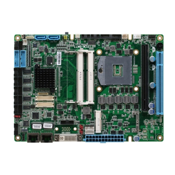
PCM-QM77
Aaeon PCM-QM77 Manuals
Manuals and User Guides for Aaeon PCM-QM77. We have
2
Aaeon PCM-QM77 manuals available for free PDF download: Manual, User Manual
Aaeon PCM-QM77 User Manual (161 pages)
Brand:
Aaeon
| Category:
Motherboard
| Size: 3 MB
Table of Contents
Copyright Notice
2
Table of Contents
11
Chapter 1 - Product Specifications
16
Pcm-Qm77
16
Specifications
17
Chapter 2 - Hardware Information
20
Dimensions
21
Jumpers and Connectors
23
List of Jumpers
25
LVDS Port 2 Operating VDD Selection (JP1)
26
LVDS Port 2 Backlight Inverter VCC Selection (JP1)
26
LVDS Port 1 Backlight Lightness Control Mode Selection (JP2)
26
LVDS Port 2 Backlight Lightness Control Mode Selection (JP3)
26
LVDS Port 1 Operating VDD Selection (JP4)
27
LVDS Port 1 Backlight Inverter VCC Selection (JP4)
27
COM6 Pin9 Function Selection (JP5)
27
COM2 Pin9 Function Selection (JP6)
27
AT/ATX Power Supply Mode Selection (JP8)
28
Front Panel Connector (JP9)
28
Clear ME Jumper (JP10)
29
Clear CMOS Jumper (JP10)
29
Touch Screen 4/5-Wire Mode Selection (JP11) (Optional)
29
List of Connectors
30
DVI Connector (CN1)
32
Stereo Audio Output Connector (CN2)
33
Ethernet#2 Connector (CN3) (Optional)
33
Ethernet#1 Connector (CN4) (Optional)
34
Ethernet#2 Connector (CN5)
35
Ethernet#1 Connector (CN6)
35
ATX Power Connector (CN7)
36
LVDS Port 2 Inverter / Backlight Connector (CN8)
37
LVDS Port 1 Inverter / Backlight Connector (CN9)
37
Audio In/Out/CD-In and MIC Connector (CN10)
38
D-SUB CRT Connector (CN11) (Optional)
38
CRT Connector (CN12)
39
Msata Slot (CN13)
40
Ethernet#1 LED Indicator (CN14)
42
COM Port 2 (CN15)
43
COM Port 1 (CN16)
45
Ethernet#2 LED Indicator (CN17)
45
LVDS Port 2 (CN18)
46
COM Port 4 (CN19)
47
COM Port 3 (CN20)
48
LVDS Port 1 (CN21)
49
LPC Port (CN22)
50
COM Port 6 (CN23)
51
COM Port 5 (CN24)
53
PCI Slot (CN25)
53
COM Port 8 (CN26)
54
COM Port 7 (CN27)
54
Pcie [X16] Slot (CN28)
55
DDR3 SO-DIMM Channel B Slot (CN29)
55
DDR3 SO-DIMM Channel a Slot (CN30)
55
COM Port 10 (CN31)
55
COM Port 9 (CN32)
56
USB 3.0 Ports 1 and 2 (CN34)
57
USB 3.0 Ports 3 and 4 (CN35)
58
USB 2.0 Ports 5 and 6 (CN36)
59
USB 2.0 Ports 7 and 8 (CN37)
59
PS/2 Keyboard/Mouse Combo Port (CN38)
60
Irda Connector (CN39) (Optional)
60
SATA Port 2 Connector (CN40)
61
SATA Port 1 Connector (CN41)
61
Output for SATA HDD (CN43)
62
LPT Connector (CN44)
62
System Fan Connector (CN45)
64
Digital IO Port 1 Connector (CN46)
64
Digital IO Port 2 Connector (CN47)
65
Touch Screen Connector (CN48) (Optional)
65
CPU FAN Connector (CN49)
67
UIM Card Connector (CN50)
67
Minicard Slot (CN51)
67
Cfast Slot (CN52)
70
Chapter 3 - BIOS Setup
71
System Test and Initialization
72
AMI BIOS Setup
73
Setup Submenu: Main
74
Setup Submenu: Advanced
75
Advanced: ACPI Management
77
Advanced: RTC Wake Settings
78
Advanced: Trusted Computing
80
Advanced: CPU Configuration
81
Advanced: Dynamic Digital IO Configuration
82
Advanced: SATA Configuration
83
Advanced: Intel TXT (LT) Configuration
85
Advanced: AMT Configuration
86
Advanced: USB Configuration
87
Advanced: F81216 Second Super IO Configuration
89
Advanced: Super IO Configuration
90
Super IO Configuration: Serial Port X Configuration
91
Advanced: Parallel Port Configuration
93
Advanced: F81866 H/W Monitor
95
Advanced: Smart Fan Configuration
96
Advanced: CPU PPM Configuration
98
Setup Submenu: Chipset
99
Chipset: PCH-IO Configuration
100
Chipset: System Agent (SA) Configuration
102
System Agent (SA) Configuration: Graphics Configuration
103
Graphics Configuration: LCD Control
105
Setup Submenu: Boot
108
Boot: BBS Priorities
109
Setup Submenu: Security
110
Setup Submenu: Save & Exit
112
Chapter 4 - Drivers Installation
113
Product CD/DVD
114
Appendix A - Watchdog Timer Programming
120
Watchdog Timer Registers
121
F81866 Watchdog Timer Initial Program
124
Appendix B - I/O Information
126
I/O Address Map
127
B.1 I/O Address Map
127
Memory Address Map
129
IRQ Mapping Chart
130
DMA Channel Assignments
133
Appendix C - Mating Connectors
134
List of Mating Connectors and Cables
135
Appendix D - RAID & AHCI Settings
138
Setting RAID
139
D.1 Setting RAID
139
Setting AHCI
146
D.2 Setting AHCI
146
Appendix E - Electrical Specifications for I/O Ports
150
Electrical Specifications for I/O Ports
151
Appendix F - Digital I/O Ports
153
Digital I/O Ports
154
F.1 Digital I/O Ports
154
Advertisement
Aaeon PCM-QM77 Manual (170 pages)
Compact Board
Brand:
Aaeon
| Category:
Motherboard
| Size: 2 MB
Table of Contents
Table of Contents
5
Chapter 1 General Information
10
Introduction
11
Features
12
Specifications
13
Chapter 2 Quick Installation Guide
16
Safety Precautions
17
Location of Connectors and Jumpers
18
Mechanical Drawing
20
List of Jumpers
22
List of Connectors
23
Setting Jumpers
26
LVDS Port 2 Operating VDD Selection (JP1)
27
LVDS Port 2 Backlight Inverter VCC Selection (JP1)
27
Selection (JP3)
28
LVDS Port 1 Operating VDD Selection (JP4)
28
LVDS Port 1 Backlight Inverter VCC Selection (JP4)
29
COM6 Pin9 Function Selection (JP5)
29
COM2 Pin9 Function Selection (JP6)
30
AT/ATX Power Supply Mode Selection (JP8)
30
Front Panel Connector (JP9)
31
Clear ME Jumper (JP10)
31
Clear CMOS Jumper (JP10)
32
Touch Screen 4/5-Wire Mode Selection (JP11)
32
DVI Connector (CN1)
32
Stereo Audio Output Connector (CN2)
34
Ethernet#2 Connector (CN3) (Optional)
35
Ethernet#1 Connector (CN4) (Optional)
35
Ethernet#2 Connector (CN5)
36
Ethernet#1 Connector (CN6)
37
ATX Power Connector (CN7)
38
LVDS Port 2 Inverter / Backlight Connector (CN8)2-24
39
LVDS Port 1 Inverter / Backlight Connector (CN9)2-25
40
Audio In/Out/CD-In and MIC Connector (CN10)
40
D-SUB CRT Connector (CN11) (Optional)
41
CRT Connector (CN12)
42
Msata Slot (CN13)
43
Ethernet#1 LED Indicator (CN14)
46
COM Port 2 (CN15)
47
COM Port 1 (CN16)
49
Ethernet#2 LED Indicator (CN17)
50
LVDS Port 2 (CN18)
50
COM Port 4 (CN19)
52
COM Port 3 (CN20)
53
LVDS Port 1 (CN21)
54
LPC Port (CN22)
56
COM Port 6 (CN23)
57
COM Port 5 (CN24)
59
PCI Slot (CN25)
60
COM Port 8 (CN26)
60
COM Port 7 (CN27)
61
PCI-Express[X16]Slot (CN28)
61
DDR3 SO-DIMM Channel B Slot (CN29)
61
DDR3 SO-DIMM Channel a Slot (CN30)
61
COM Port 10 (CN31)
62
COM Port 9 (CN32)
62
USB 3.0 Ports 1 and 2 (CN34)
63
USB 3.0 Ports 3 and 4 (CN35)
65
USB 2.0 Ports 5 and 6 (CN36)
66
USB 2.0 Ports 7 and 8 (CN37)
67
PS/2 Keyboard/Mouse Combo Port (CN38)
67
Irda Connector (CN39) (Optional)
68
SATA Port 2 Connector (CN40)
69
SATA Port 1 Connector (CN41)
69
Output for SATA HDD (CN43)
70
LPT Connector (CN44)
70
System Fan Connector (CN45)
72
Digital IO Port 1 Connector (CN46)
72
Digital IO Port 2 Connector (CN47)
73
P C M - Q
74
Touch Screen Connector (CN48)
74
CPU FAN Connector (CN49)
76
UIM Card Connector (CN50)
76
Mini-Card Slot (CN51)
77
Cfast Slot (CN52)
80
Chapter 3 AMI BIOS Setup
83
System Test and Initialization
84
AMI BIOS Setup
85
Chapter 4 Driver Installation
123
Appendix A Programming the Watchdog Timer
131
Programming
132
F81866 Watchdog Timer Initial Program
135
Appendix B I/O Information
138
I/O Address Map
139
Memory Address Map
140
IRQ Mapping Chart
141
DMA Channel Assignments
142
Appendix C Mating Connector
143
List of Mating Connectors and Cables
144
Appendix D RAID & AHCI Settings
152
D.2 Setting AHCI
153
E.1 Electrical Specifications for I/O Ports
159
F.1 Digital I/O
163
Advertisement
Related Products
Aaeon Compact Board PCM-9452
Aaeon PCM-5896
Aaeon PCM-6890B
Aaeon PCM-7890
Aaeon PCM-4894
Aaeon PCM-6890
Aaeon PCM-6894
Aaeon PCM-6892 Rev.B
Aaeon PCM-4897
Aaeon PCM-5894C
Aaeon Categories
Motherboard
Computer Hardware
Desktop
Touch Panel
Control Unit
More Aaeon Manuals
Login
Sign In
OR
Sign in with Facebook
Sign in with Google
Upload manual
Upload from disk
Upload from URL