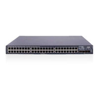
H3C S5800-56C Manuals
Manuals and User Guides for H3C S5800-56C. We have 3 H3C S5800-56C manuals available for free PDF download: Installation Manual, Instruction Manual
Advertisement
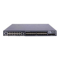
H3C S5800-56C Instruction Manual (30 pages)
Brand: H3C
|
Category: Network Hardware
|
Size: 3.04 MB
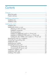
Table of Contents
Advertisement
Advertisement