Juniper EX4300 Quick Start Manual
Hide thumbs
Also See for EX4300:
- Hardware manual (415 pages) ,
- Manual (9 pages) ,
- Hardware documentation (966 pages)
Advertisement
Quick Links
Download this manual
See also:
Feature Manual
EX4300 Switch Quick Start
Juniper Networks EX4300 Ethernet Switches provide connectivity for high-density environments and scalability for growing
networks. These switches can be deployed wherever you need high density of Gigabit Ethernet ports or redundancy. Typically,
EX4300 switches are used in large branch offices, campus wiring closets, and data centers. In data centers, EX4300 switches
can be positioned as top-of-rack switches—the top devices in a rack—to provide connectivity for all the devices in the rack and
provide options for optimized airflow (hot aisle/cold aisle).
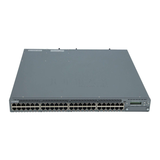
The 48-port EX4300 switches with multigigabit ports—EX4300-48MP and EX4300-48MP-S—provide 24 built-in
10/100/1000BASE-T Ethernet network ports, 24 built-in 100/1000/2500/5000/10000BASE-T Ethernet network ports, and four
built-in 40-Gigabit Ethernet quad small form-factor pluggable plus (QSFP+) ports that can house 40-Gigabit QSFP+ transceivers.
The 24 built-in 10/100/1000BASE-T Ethernet network ports support 10 Mbps, 100 Mbps, and 1 Gbps speeds. The 24 built-in
100/1000/2500/5000/10000BASE-T Ethernet network ports support 100 Mbps, 1 Gbps, 2.5 Gbps, 5 Gbps, and 10 Gbps speeds.
All network ports are equipped for PoE+ and provide up to 95 watts of power. The QSFP+ ports are configured as Virtual Chassis
Ports (VCPs) by default. You can use them to connect the switches to other devices in a Virtual Chassis configuration.
EX4300 switches support two power supplies, installed on the rear panel. The cooling system in an EX4300 switch consists of
two fan modules, installed on the rear panel, and a single fan in each power supply.
Tools and Parts Required for Installation
NOTE:
See
the
release-independent/junos/information-products/pathway-pages/ex-series/ex4300/ex4300.html
To mount a Juniper Networks EX4300 Ethernet Switch on two posts of a rack, you need:
Two mounting brackets and eight mounting screws—provided
Screws to secure the chassis to the rack or cabinet—not provided
Phillips (+) screwdriver, number 2—not provided
Electrostatic discharge (ESD) grounding strap—not provided
Fan module—if not already installed
To connect the switch to earth ground, you need:
A grounding cable (minimum 14 AWG (2 mm²), minimum 90° C wire, or as permitted by the local code), a grounding lug
(Panduit LCC10-14BWL or equivalent), a pair of 10-32 x .25-in. screws with #10 split-lock washers, and a pair of #10 flat
washers—none provided
To connect power to the switch, you need:
For models that are powered by AC power—An AC power supply (if not already installed), an AC power cord with a plug
appropriate for your geographical location, and a power cord retainer
complete
hardware
documentation
at
https://www.juniper.net/documentation/en_US/
.
Advertisement

Related Manuals for Juniper EX4300


Summary of Contents for Juniper EX4300
- Page 1 Ports (VCPs) by default. You can use them to connect the switches to other devices in a Virtual Chassis configuration. EX4300 switches support two power supplies, installed on the rear panel. The cooling system in an EX4300 switch consists of two fan modules, installed on the rear panel, and a single fan in each power supply.
- Page 2 Register product serial numbers on the Juniper Networks website and update the installation base data if there is any addition or change to the installation base or if the installation base is moved. Juniper Networks will not be held accountable for not meeting the hardware replacement service-level agreement for products that do not have registered serial numbers or accurate installation base data.
- Page 3 2, and Figure Figure 1: Installing an AC Power Supply in EX4300 Switches Except EX4300-48MP and EX4300-48MP-S Figure 2: Installing an AC Power Supply in EX4300-48MP and EX4300-48MP-S Figure 3: Installing a DC Power Supply in EX4300 Switches Except EX4300-48MP and EX4300-48MP-S If the power supply slot has a cover panel on it, loosen the captive screws on the cover panel by using your fingers or the screwdriver.
- Page 4 For example, if you want to front-mount EX4300 switches except EX4300-48MP and EX4300-48MP-S switches, align the brackets along the front of the side panel (see Figure 6).
- Page 5 EX4300 Switch Quick Start Figure 6: Attaching the Mounting Bracket to the Side Panel of EX4300 Switches Except EX4300-48MP and EX4300-48MP-S Switches Figure 7: Attaching the Mounting Bracket to the Side Panel of EX4300-48MP and EX4300-48MP-S Switches Figure 8: Mounting Bracket Attached to the Side Panel of EX4300-48MP and EX4300-48MP-S Switches Attach the brackets to the chassis by using the mounting screws.
-
Page 6: Part 4: Connect Power To The Switch
Grounding is required for DC systems and recommended for AC systems. An AC-powered switch gets additional grounding when you plug the power supply in the switch into a grounded AC power outlet by using the power cord. NOTE: The power supply slots are on the rear panel. Copyright © 2018, Juniper Networks, Inc. - Page 7 Figure 11): Figure 10: Connecting Power to an EX4300 Switch Powered by AC Power Supply Except EX4300-48MP and EX4300-48MP-S Figure 11: Connecting Power to EX4300-48MP and EX4300-48MP-S Push the end of the retainer strip into the hole next to the inlet on the power supply faceplate until it snaps into place.
- Page 8 EX4300 Switch Quick Start To connect power to an EX4300 switch powered by DC power supply: NOTE: EX4300-24T, EX4300-24P, EX4300-32F, EX4300-48T, EX4300-48T-AFI, EX4300-48P, EX4300-48MP, and EX4300-48MP-S models do not support DC power. EX4300-24T-S, EX4300-24P-S, EX4300-32F-S, EX4300-32F-DC, EX4300-48T-S, EX4300-48T-DC, EX4300-48T-DC-AFI, and EX4300-48P-S models support DC power.
-
Page 9: Part 5: Perform Initial Configuration
8 lb-in. (0.9 Nm) and 9 lb-in. (1.02 Nm) of torque to the screws. If you have a second installed power supply, connect it in the same way you did the first. Figure 12: Connecting Power to an EX4300 Switch Powered by DC Power Supply Replace the terminal block cover. - Page 10 Specify the IP address and gateway of the management interface. Use this IP address to connect to the switch. (Optional) Specify the SNMP read community, location, and contact to configure SNMP parameters. (Optional) Specify the system date and time. Select the time zone from the list. Copyright © 2018, Juniper Networks, Inc.
-
Page 11: Safety Warnings Summary
Juniper Networks, the Juniper Networks logo, Juniper, and Junos are registered trademarks of Juniper Networks, Inc. in the United States and other countries. All other trademarks, service marks, registered marks, or registered service marks are the property of their respective owners. Juniper Networks assumes no responsibility for any inaccuracies in this document.
Need help?
Do you have a question about the EX4300 and is the answer not in the manual?
Questions and answers