
Subscribe to Our Youtube Channel
Related Manuals for HIGHLEAD GC20688-DC


Summary of Contents for HIGHLEAD GC20688-DC
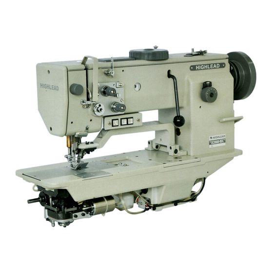
- Page 1 GC20688-DC/GC20688-BDC Compound-Feed, Heavy Material Lockstitch Sewing Machine With Edge Cutter Instruction Manual Parts Catalog SHANGHAI HUIGONG NO.3 SEWING MACHINE FACTORY...
-
Page 2: Table Of Contents
----- CONTENTS ----- 1. PRECAUTIONS BEFORE STARTING OPERATION···············································································1 Safety precautions ····································································································································1 Precaution before Starting Operation ····································································································1 Precaution for Operating Conditions·····································································································1 2. SPECIFICATIONS ·········································································································································1 3. PREPARATION BEFORE STARTING TO OPERATE ·············································································2 Connection of control box ·······················································································································2 Oil pan·······················································································································································3 Operation panel········································································································································3 Adjusting the needle stop position··········································································································3 Lubrication ···············································································································································4 4. - Page 3 Adjusting the presser foot timing ·········································································································14 Adjusting the fixed knife position·········································································································15 Adjusting the thread holding spring position ······················································································15 Adjusting the knife timing position ······································································································15 Adjusting the driving knife height········································································································15 Adjusting the driving knife stop position·····························································································16 Adjusting the driving knife operating position ···················································································16 Adjusting the thread trimming timing·································································································17 Safety clutch ···········································································································································17 Regulate the atmospheric pressure...
-
Page 4: Precautions Before Starting Operation
Otherwise, machine failure may result. (2) Avoid using the machine in dusty conditions. Avoid using the machine in areas where too much electrical noise, resulted from the high-frequency welder and others, is generated SPECIFICATIONS Item GC20688-DC GC20688-BDC Max. Speed 3000rpm 2800rpm... -
Page 5: Preparation Before Starting To Operate
3. PREPARATION BEFORE STARTING TO OPERATE 1) Connection of control box It shows the connection of the electrical wires of the whole machine on the right picture. When the machine needs to be assembled, each line should be linked to the right joint according to the instruction of the picture. -
Page 6: Oil Pan
2) Oil pan (1) Install the oil pan 3 to the underside of the worktable 1 in the place shown in the illustration using the nails 2. (2) From front view, the oil pan 3 to the side is 60mm; from right view, the oil pan 3 to the side is 80mm. 3) Operation panel (1) Install the operation panel 1 to the set plate 2 with the three screws 3. -
Page 7: Lubrication
a. Turn off the power switch. b. Loosen the screw 4, and then remove the cover 3. c. When the red mark stops in a position over the mark on the belt cover, the needle up stop position disc 1 should be turned in the opposite direction as the direction of machine pulley rotation. -
Page 8: Adjusting Of The Thread Regulator
2) Adjusti g of the thread regulator The th d regulator 9 (see the right picture) regulates the amount of needle thread necessary for stitch formation. The setting depends on the following factors: material thickness, yarn characteristics and stitch length. The thread regulator is fitted with slots for this purpose. -
Page 9: Adjusting The Lower-Thread Tension
Adjusting the lower-thread tension he lower-thread tension should be set in accordance with the type of seam required. Adjust the tension with screw 7. (See the picture of above) Installing the needle Note: Before attach needle, b e sure to turn off the power. 1) Turn the b alance wheel by hand to raise the needle bar to its high... -
Page 10: Using The Manual Switches
above) Use feed adjustment dial 2 to set the big s titch length. Use feed adjustment dial 3 to set the little stitch lengt h. The sewing machine will switch between t he two stitch lengths each time the stitch length change switch is pressed. -
Page 11: Adjusting The Trailing Length After Thread Trimming
Hold a piece of paper next to the hook and check if sufficient oil is spun oil onto the paper. Remove cover plate 2. Loosen screw 3 until the tube 1 no longer moves. This is the case when the tube is in the center of the drilled hole. -
Page 12: Adjusting The Feed Dog
16) Adjusting the feed dog Set the feed adjustment dials to the minimum settings. Then adjust as follows so that the feed dog 1 is at its highest position (0.5mm above the top of t he needle plate 2) when the needle bar is at its lowest position. -
Page 13: Adjusting The Gap Between The Needle And The Rotary Hook Tip
(4) Loosen the screw 3 and then move the needle bar 1 up or down to adjust so that the distance from the tting surface of the needle plate 2 to the end of the needle bar 1 is 18.5 mm. (5) Tighten the screw 3, install the face plate. -
Page 14: Adjusting The Needle And Feed Mechanism Timing
rotection 1 without being displaced. Move needle in looping stroke position by pulley. In looping stroke position the hook tip is at the level of e middle of the needle. Press n eedle against hook protection 1 manually. The needle should not touch the hook tip. -
Page 15: Adjusting The Opener Position
d. Tighten the screws 3 22) Adjusting the opener position Adjust so that the clearance between the needle plate 3 and th e stopper 4 of the inner rotary hook 2 is 0.5-0.7 when the opener 1 is at its closest position to the inner rotary hook 2. -
Page 16: Adjusting The Alternating Presser Foot Movement Amount
(3) Raise the presser lifters bar 1 and then loosen the screw 2. (4) Move the outer presser bar up or down to adjust so that the height of the outer presser foot 7 is 9 mm. (5) While the stopper pin 6 is touching against the notch B in the presser foot lifter connection 5 and while pushing t he presser lifter shaft so that there is no play in the thrust direction, tighten the screw 2. -
Page 17: Adjusting The Presser Foot Timing
are lo wered and the machine pulley is tur ned. a. Set the feed adjustment dials to the maxim settings. b. Open the cover 4 c. Turn the alternating presser foot movement dial to the “B” position. d. Loosen the screw 3 e. -
Page 18: Adjusting The Fixed Knife Position
26) Adjusting the fixed knife position The distance from the groove of slide plate to the fixed knife 1 should be 26 mm. Furthermore, the distance from the edge of the need le plate to the left edge of the tip of the fixed knife 1 should be 4 mm. Loosen the two bolts 2. -
Page 19: Adjusting The Driving Knife Stop Position
(2) Move the driving knife shaft 6 up or down to adjust the position of the driving knife 1. (3) Tighten the screws 2 and 5 on the setting collars again. 30) Adjusting the driving knife stop position The distance from the blade of the fixed knife 2 to the end of the driving knife 1 should be 0.5mm when the driving knife 1 has moved as far as possible toward the fixed knife 2. -
Page 20: Adjusting The Thread Trimming Timing
(4) Loosen the bolt 4. (5) Set the plunger 2 to the position where it projects as far as possible to the left. (6) Turn the machine pulley to move the roller 6 of the driving knife arm to the outermost side (right side) of the thread trimmer cam 5. -
Page 21: Regulate The Atmospheric Pressure
(1) Set free blocked hook. (2) Stick a pin in drill-hole 1 of the outer clutch disc. (3) Turn the pulley un til the pin can be stuck in the drill-holes of both clutch parts. (4) Turn the pulley forwards and backwards until the hoo k is freely movable again. -
Page 22: Stroke Of The Knife
1) I dle of the knife when th e vertical cutter is turned off. Press the operating lever 3 to the right. The vertical c utter does not function. Turn the hand-wheel. When the v ertical cutter is turned off the knife should not move during the sewing machine op eration. -
Page 23: Timing Of Knife Movement
6) Timing of knife movement Loosen screws7(2×). Turn eccentric 8 on the shaft. The knife and the presser foot should reach their upper dead centers at the same time. Tighten screws 7(2×) again. The tie rod 11 must touch the groove in the eccentric with its knots. -
Page 24: Arm Bed And Its Accessories
A.ARM BED MECHANISM — 21 —... - Page 25 A.ARM BED MECHANISM Fig. Part No. Description Remarks HF914B8001 Screw M5×12 H005001040 Washer H415040080 Screw M4×8 HF927B8001 Thread take-up cover HE41B38001 Thread take-up cover HF930B8001 Plug HF933B8001 Dial HF935B8001 Dial shaft HF936B8001 Guard plate HF931B8001 Cover H003024040 Hexagonal nut H005001040 Washer H401040060 Screw M4×6 HA710B0671 Pre-tension adjusting nut...
- Page 26 A.ARM BED MECHANISM Fig. Part No. Description Remarks HF967B8001 Winder wheel H7331D8001 Rubber ring H431050050 M5×5 Screw HF999B8001 Cord cover H7331G8001 Screw HF914B8001 Screw M5×12 HF915B8001 Screw M5×12 HF918B8001 HF913B8001 Face plate HF919B8001 HF920B8001 Oil pillow HF998B8001 HE61B68001 Slide Plate HE61B98001 Needle plate HE62B38001...
- Page 27 A.ARM BED MECHANISM Fig. Part No. Description Remarks HF979I8001 Belt tensioner H415040060 Screw M4×6 HF970B8001 Bobbin seat HE41B58001 Bobbin seat HF946B8001 Washer HE62B08001 Fixed knife HE62B88001 Fixed knife HE62B18001 Fixed knife plate H415030100 Screw M3×10 H005004030 Washer HE60I77101 Pushing plate —...
-
Page 28: Thread Tension Regulator Mechanism
B.THREAD TENSION REGULATOR MECHANISM — 25 —... - Page 29 B.THREAD TENSION REGULATOR MECHANISM Fig. Part No. Description Remarks H003002050 Nut HF930C8001 Thead hook HF929C8001 Thread tension stud HA112B0693 Thread tension discs HA710B0672 Tension spring HA710B0671 Tension adjusting nut HF907C8001 Thread tension stud HF917C8001 Thread guide H3221B6817 Thread tension releasing pin H3221B6811 Shoulder screw H7316B8001 Screw HF925C8001 Thread guide...
- Page 30 B.THREAD TENSION REGULATOR MECHANISM Fig. Part No. Description Remarks H415040100 Screw HF906C8001 Magnet support HF922C8001 Solenoid H403050120 Screw M5×12 H4710C8001 Tension spring H003002040 Nut H003045040 Nut — 27 —...
-
Page 31: Sewing Mechanism
C.NEEDLE BAR AND THREAD TAKE-UP MECHANISM — 28 —... - Page 32 C.NEEDLE BAR AND THREAD TAKE-UP MECHANISM Fig. Part No. Description Remarks H6715C8001 Screw H431060060 Screw M6×6 HF907D8001 Crank H431060060 Screw M6×6 HF914B8001 Screw HF905D8001 Upper shaft H3205J0662 Ball bearing H431080100 Screw M8×10 HF913D8001 Counterweight H007009200 Retainer ring HF921D8001 Ball bearing HF918D8001 Bushing H431060060 Screw M6×6...
- Page 33 C.NEEDLE BAR AND THREAD TAKE-UP MECHANISM Fig. Part No. Description Remarks HF926G8001 Bushing HF922G8001 Needle bar link H431030050 Screw M3×5 HD726G8001 Screw M4×12 HF924G8001 Needle bar holder HF928G8001 Threaded bolt HF927G8001 Slide block HF938G8001 Oil wick H415040100 Screw M4×10 HF933G8001 Slide guide HF939G8001 Oil feeding pipe HF936G8001 Oil pipe HF937G8001 Oil wick...
-
Page 34: Presser Foot Mechanism
D.PRESSER FOOT MECHANISM — 31 —... - Page 35 D.PRESSER FOOT MECHANISM Fig. Part No. Description Remarks H428050080 Screw M5×8 HF919E8001 Support pin HF906E8001 Adjusting bracket H428050080 Screw M5×8 HF912E8001 Oil wick HF911E8001 Oil pipe HF908E8001 Oil wick HF913E8001 Plate H005018050 Washer H415050100 Screw M5×10 D100 HE60E88001 Pull spring HF956G8001 Oil feeding pipe HF917E8001 Link pin HF916E8001 Link...
- Page 36 D.PRESSER FOOT MECHANISM Fig. Part No. Description Remarks H415030060 Screw M3×6 HF974E8001 Plate HF973E8001 Oil satchel HF972E8001 Draught rod HF961E8001 Plug HF983E8001 Oil pipe HF984E8001 Oil wick HF982E8001 Spring HF986E8001 Oil wick HF977E8001 Pin H401040040 Screw M4×4 HF977E8001 Pin HF978E8001 Oil wick HF979E8001 Stopper claw HF925F8001 Joint HF926F8001 Pin...
-
Page 37: Upper Feed Lifting Rock Shaft Mechanism
E.UPPER FEED LIFTING ROCK SHAFT MECHANISM — 34 —... - Page 38 E.UPPER FEED LIFTING ROCK SHAFT MECHANISM Fig. Part No. Description Remarks H007013080 E-type retaining ring 8 HF965F7101 Press adjusting plate assy HF963F8001 Pin HF961F7101 Press adjusting dial H007013050 E-type retaining ring 5 H609030080 Spring pin HF976F8001 Spring support (U) HF972F8001 Spring HF975F8001 Hose HF973F8001 Shaft HF974F8001 Spring support (D)
- Page 39 E.UPPER FEED LIFTING ROCK SHAFT MECHANISM Fig. Part No. Description Remarks H428060160 Screw H415040550 Screw H005008040 Spring washer H005004040 Washer — 36 —...
-
Page 40: Stitch Regulator Mechanism
F.STITCH REGULATOR MECHANISM — 37 —... - Page 41 F.STITCH REGULATOR MECHANISM Fig. Part No. Description Remarks HF925H8001 Spring HF924H8001 Washer HF922H8001 Feed adjusting arm HF923H8001 Pin H431050080 Bolt M5×8 HF914H8001 Feed adjusting screw (long) HA700F2030 Positioning pin H3200F2110 Spring HA109F0674 O ring HA720F0687 Spring HA720F0683 Support plate HA7421F120 Feed adjusting dial HF909H8001 Feed adjusting dial plate(L) HA720F0685 Bushing HA720F0686 Screw...
- Page 42 F.STITCH REGULATOR MECHANISM Fig. Part No. Description Remarks HF941H8001 HF973H8001 Pull spring H424100100 Thread pin M10×10 H3100D2090 Presser spring HF963H8001 Key HF966H8001 Oil seal HF958H8001 Shaft HF967H8001 Oil seal HF961H8001 Guide H005009050 Elastic washer H415050160 Screw M5×16 HF974H8001 Pothook — 39 —...
-
Page 43: Feeding And Feed Lifting & Rotating Hook Shaft Mechanism
G.FEEDING AND FEED LIFTING & HOOK SHAFT MECHANISM — 40 —... - Page 44 G.FEEDING AND FEED LIFTING & HOOK SHAFT MECHANISM Fig. Part No. Description Remarks HF928I8001 Feed shaft HF959G8001 Rubber cap HF965G8001 Adjusting shaft collar H415040120 Bolt M4×12 HF927E8001 Bushing(L) HF931I8001 Thurst ring HF930I8001 C-type retaining ring HF941I8001 Tube HF942I8001 Oil wick HF937I8001 Bushing HF945I8001 Washer HF935I8001 Feed arm(L)
- Page 45 G.FEEDING AND FEED LIFTING & HOOK SHAFT MECHANISM Fig. Part No. Description Remarks HF927E8001 Bushing(L) HF90EI8001 Bushing(R) H428060100 Bolt M6×10 H429060100 Bolt M6×10 HF975J8001 Coupling claw(L) HF978J8001 Toothed wreath HF977J8001 Coupling craw(R) HC01118026 O ring HF988I8001 Oil seal HF987I8001 Bushing(L) HF992I8001 Bolt H34412C110 Plunger spring HF966I8001 Plunger...
-
Page 46: Hook Saddle Mechanism (Right)
H.HOOK SADDLE MECHANISM — 43 —... - Page 47 H.HOOK SADDLE MECHANISM Fig. Part No. Description Remarks HG013J8001 Link lever HF920J8001 collar H428050050 Bolt M5×5 H007013040 E-type stop ring 4 HF934J8001 Pin HG012J8001 Thread trimmer arm(S) H415040120 Bolt M4×12 HF939J8001 Pin H007013030 E-type stop ring 4 H415060220 Bolt M6×22 HF92BJ8001 Spacer HF92CJ8001 Eccentric collar HG017J8001 Driving knife connection...
- Page 48 H.HOOK SADDLE MECHANISM Fig. Part No. Description Remarks HF984J8001 Bearing HF91CJ7101 Gear base assy HC01095018 Wave washer H005014060 Belleville spring washer HF91IJ8001 Adjusting block HF91JJ8001 Hexagonal nut HF91AJ8001 Driving gear HF947J8001 Oil joint(M) H415040080 M4×8 Bolt(short) H415040120 M4×12 Bolt(long) HF958J8001 Oil seal HF942J8001 Thread trimmer cam...
- Page 49 H.HOOK SADDLE MECHANISM Fig. Part No. Description Remarks HF967J8001 Driving shaft HF963J8001 Boll bushing HF962J8001 Lower shaft holder HF965J8001 Screw HF966J8001 Bolt HF970J8001 Washer HF969J8001 Driving gear H403030080 Screw HC01387018 O-ring H415040100 Bolt M4×10 HG025J8001 Thread trimmer solenoid HG019J8001 Solenoid setting bracket H415040080 Bolt M4×8 HG020J8001 Solenoid setting plate...
-
Page 50: Oil Lubrication Mechanism
I.OIL LUBRICATION MECHANISM — 47 —... - Page 51 I.OIL LUBRICATION MECHANISM Fig. Part No. Description Remarks H401050080 Bolt M5×8 H005018050 Spacer HF909K8001 Oil wick support HF917K8001 Oil joint HF908K8001 Tube guide HF906K8001 Felt HF907K8001 Oil wick φ4×850 HF905K8001 Oil tube φ7×φ5×740 HF918K8001 Oil tube φ7×φ5×600 HF914K8001 Felt HF915K8001 Oil wick φ4×680 HF913K8001 Oil tube φ7×φ5×580...
- Page 52 I.OIL LUBRICATION MECHANISM Fig. Part No. Description Remarks HF923K8001 Oil pipe HE60K48001 Oil pipe φ7×φ5×100 HE60K58001 Oil pipe φ7×φ5×110 HF926K8001 Support spring HF932K8001 Felt part HA300I2040 Cable tie HF934K8001 Oil pipe φ3×φ5×250 HF937K8001 Oil pipe φ3×φ5×600 HE60K88001 Oil pipe φ3×φ5×600 —...
-
Page 53: Accessories
J.ACCESSORIES — 50 —... - Page 54 J.ACCESSORIES Fig. Part No. Description Remarks HA307J0671 Hinge support HF914L8001 Hinge H411060100 Screw HF905L8001 Head cushion HF971B8001 Bobbin HE41J38001 Bobbin HA100J2170 Oil tank H2004O0069 Oiler HF904B7101 Neddle HF913L8001 Detector setting plate HA200J2030 Cotton stand assy HA100J2180 Cover HF904L8001 Oil plate 16250 Nail HB01001025 Hexagonal wrench (2.5)
-
Page 55: Pneumatic Control Mechanism
K.PNEUMATIC CONTROL MECHANISM — 52 —... - Page 56 K.PNEUMATIC CONTROL MECHANISM Fig. Part No. Description Remarks HF930M8001 connecting box base HF924M8001 PCB board HF932M8001 connecting box screw H409040160 screw H415030120 screw HF931M8001 connecting box cover HF925M7101 control box wire assy H801045200 screw HA300J2230 washer HE60M47101 pneumatic assy HA300I2040 nylon fixer HF958M8001 windpipe 300mm φ6 HF914M8001 windpipe...
-
Page 57: Kniffe Mechanism
L.KNIFFE MECHANISM — 54 —... - Page 58 L.KNIFFE MECHANISM Fig. Part No. Description Remarks HE60N68001 pedestal H415040160 screw M4×16 HE60N78001 shaft HE60N98001 Setting bracket HE61N08001 bushing HE61N18001 knife HE69N38001 knife HE61N28001 bracket H411040100 screw M4×10 H005001040 washer H003002040 nut H415030060 screw M3×6 H005001030 washer HE61N38001 connecting block H415040200 screw M4×20 H005001040 washer...
- Page 59 L.KNIFFE MECHANISM Fig. Part No. Description Remarks HE64N18001 washer H417040180 M4×18 screw H003002040 HE64N28001 bushing HE64N38001 Spring HE64N57101 Cam wheel assy H428060080 M6×8 screw H415040080 M4×8 screw H005001040 washer HE64N88001 wheel HE64N97101 link HE65N18001 HE65N28001 oil wick HE65N48001 link H427050060 M5×6 screw HE65N68001...
- Page 60 L.KNIFFE MECHANISM Fig. Part No. Description Remarks HE68N28001 pin HE62N68001 bushing HE68N48001 lever HE68N58001 bushing HE68N68001 link H415050100 screw HE68N88001 pin HE68N98001 block HE69N08001 control lever HF01080300 hand knob M8×30 HE69N18001 block H415030120 screw M3×12 HE69N28001 block H415040080 screw — 57 —...
- Page 61 SHANGHAI HUIGONG NO.3 SEWING MACHINE FACTORY ADD: 1418, Yishan Road, Shanghai, China Zip Code: 201103 Overseas Business: TEL: 86-21-64853303 FAX: 86-21-64854304 E-mail:highlead@online.sh.cn http://www.highlead.com.cn The description covered in this manual is subject to change for improvement of the commodity without notice 2010.1. Printed...
Need help?
Do you have a question about the GC20688-DC and is the answer not in the manual?
Questions and answers