
Subscribe to Our Youtube Channel
Related Manuals for HIGHLEAD GC20688 Series


Summary of Contents for HIGHLEAD GC20688 Series
-
Page 1: Instruction Manual
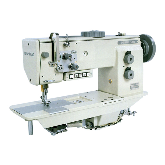
GC20688Series Compound-feed Heavy Material Lockstitch Sewing Machine Instruction Manual Parts Catalog SHANGHAI BIAOZHUN HAILING SEWING MACHINERY CO., LTD. -
Page 2: Safety Precautions
PRECAUTIONS BEFORE STARTING OPERATION Safety precautions (1) When turning the power on, keep your hands and fingers away from the area around/under the needle and the area around the pulley. (2) Power must be turned off when the machine is not used, or when the operator leaves his/her seat. (3) The power must be turned off before tilting the machine head, installing or adjusting the machine, or when replacing. -
Page 3: Preparation Before Starting To Operate
3. PREPARATION BEFORE STARTING TO OPERATE 1) Connection of control box It shows the connection of the electrical wires of the whole machine on the right picture. When the machine needs to be assembled, each line should be linked to the right joint according to the instruction of the picture. -
Page 4: Operation Panel
2) Oil pan (1) Install the oil pan 3 to the underside of the worktable 1 in the place shown in the illustration using the nails 2. (2) From front view, the oil pan 3 to the side is 60mm; from right view, the oil pan 3 to the side is 80mm. - Page 5 c. When the red mark stops in a position over the mark on the belt cover, the needle up stop position disc 1 should be turned in the opposite direction as the direction of machine pulley rotation. When the red mark stops in a position under the mark on the belt cover, Turn the disc 1 in the same direction as the pulley rotation direction.
-
Page 6: How To Use The Machine
HOW TO USE THE MACHINE 1) Threading Raise the thread take-up lever to its highest position and thread the upper thread in the following order. 2) Adjusting of the thread regulator The thread regulator 9 (see the right picture) regulates the amount of needle thread necessary for stitch formation. -
Page 7: Threading The Lower Thread
(5) After the thread has been wound on, remove the bobbin and cut the thread with the thread-trimming knife 2. 5) Threading the lower thread (1) Raise flap 1 and remove the empty bobbin. (2) Insert bobbin 2 in such a way that when the thread is unwound from it moves in the opposite direction to the gripper. -
Page 8: Adjusting The Presser Foot Pressure
9) Adjusting the presser foot pressure The presser foot pressure should be set as weak as possible, but strong enough so that the material does not slip. If the presser-adjusting dial 1 is turned clockwise, the presser foot pressure will become stronger, and if it is turned counterclockwise, the pressure will become weaker. - Page 9 Push the switch one more time after change the bobbin. The sewing machine cannot run before the switch be pushed one more time. The stitch count should be set according to the stitch length and the count of the bobbin thread. Notice: the switch is not work until the correlative functions of the control box are set. The functions please read the parameter 42, 43, 44 in the servo motor user manual.
-
Page 10: Adjusting The Trailing Length After Thread Trimming
in until the tube movement just starts and then a 1/8 turn farther. The hook lubrication is preset. Attach cover plate 2 again. Setting the hook lubrication with screw 3. (3) Lubricating wicks and felt (see the picture of above) a. -
Page 11: Adjusting The Feed Dog
16) Adjusting the feed dog Set the feed adjustment dials to the minimum settings. Then adjust as follows so that the feed dog 1 is at its highest position (0.5mm above the top of the needle plate 2) when the needle bar is at its lowest position. -
Page 12: Hook Protection
19) Adjusting of the needle and the hook timing (1) Set the stitch length to “0”. (2) Remove the needle plate. (3) Overturn the arm. (4) Loosen the screw 1 (5) Turn the machine pulley to raise the needle bar from its low position to the point that the needle rises 2.4 mm. -
Page 13: Adjusting The Opener Position
d. Turn the machine pulley until the needle bar is at its lowest position. e. Turn the lower feed cam 3 gradually until it is at the position where the needle and the feed dog do not move even when the reverse lever is moved up and down. -
Page 14: Adjusting The Presser Foot Height
screw 6. (3) Turn the machine pulley to move the opener 1 as close to the inner rotary hook 2 as possible. (4) While pressing the opener 1 against the inner rotary hook 2 with your finger, adjust so that the clearance between the needle plate 3 and the stopper 4 of the inner rotary hook 2 is 0.5-0.7 mm. - Page 15 d. Adjust the adjusting bracket collar 4. If the adjusting bracket collar 4 is be installed at the highest position, the alternating presser foot movement amount is 1-6mm. If it is at the lowest position, the alternating presser foot movement amount is 1.6-7mm. e.
-
Page 16: Adjusting The Presser Foot Timing
e. Turn the machine pulley toward you to align the tip of the needle and the top of the feed dog with the top of the needle plate. f. Move the connecting lever to adjust so that both the inner presser foot 2 and outer presser foot 1 are in contact with the top of the needle plate at this time. -
Page 17: Adjusting The Knife Timing Position
27) Adjusting the thread holding spring position (see the picture of above) The thread holding spring 1 holds the lower thread after thread trimming to prepare it for the next sewing operation. The clearance between the thread holding spring 1 and the side of the fixed knife 2 should be 1.4-1.6 (1) Loosen the two screws 3. -
Page 18: Adjusting The Driving Knife Operating Position
(3) Loosen the bolt 6. (4) Move the driving knife 1 so that the distance between the blade of the fixed knife 2 to the end of the driving knife 1 is 0.5 mm, and then tighten the bolt 6. 31) Adjusting the driving knife operating position The standard distance from the left side of... -
Page 19: Adjusting The Thread Trimming Timing
32) Adjusting the thread trimming timing The center of the pin 1, the center of the reference hole 3 and the center of the roller 4 of the driving knife arm should be in a straight line when the thread take-up lever is at the highest position. -
Page 20: Regulate The Atmospheric Pressure
(3) Tighten counter-nuts 3 again. 34) Regulate the atmospheric pressure When the air cylinder works normally, the necessary atmospheric pressure is 5.5~6bar. Can find out through the dial plate of the filtering . (1) Lifting knob 1, clockwise rotation , the pressure increases. (2)Lifting knob 1, anticlockwise rotation, the pressure is reduced —... -
Page 21: A.arm Bed And Its Accessories
A.ARM BED AND ITS ACCESSORIES — 20 —... - Page 22 A.ARM BED AND ITS ACCESSORIES Fig. Part No. Description Remarks HF914B8001 Screw M5×12 H005001040 Washer H415040080 Screw M4×8 HF927B8001 Thread take-up cover HF930B8001 Plug HF933B8001 Dial HF935B8001 Dial shaft HF936B8001 Guard plate HF931B8001 Cover H003045040 Hexagonal nut H005001040 Washer H401040060 Screw M4×6 HA710B0671 Pre-tension adjusting nut H6739B8001 Thread tension spring...
- Page 23 A.ARM BED AND ITS ACCESSORIES Fig. Part No. Description Remarks HF969B8001 Rubber ring H431050050 Screw M5×5 HF999B8001 Cord cover H7331G8001 Screw HF914B8001 Screw M5×12 HF915B8001 Screw M5×12 HF918B8001 Bar HF913B8001 Face plate HF919B8001 Bar HF920B8001 Oil pillow HF998B8001 Leg HF980B8001 Slide Plate HF988B8001 Needle plate HF989B8001 Screw HF981B8001 Slide Plate...
- Page 24 A.ARM BED AND ITS ACCESSORIES Fig. Part No. Description Remarks HG007B8001 Needle plate HG006B8001 Slide Plate — 23 —...
-
Page 25: B.thread Tension Regulator Mechanism
B.THREAD TENSION REGULATOR MECHANISM — 24 —... - Page 26 B.THREAD TENSION REGULATOR MECHANISM Fig. Part No. Description Remarks H003002050 Nut HF930C8001 Thead hook HF929C8001 Thread tension stud HA112B0693 Thread tension discs HA710B0672 Tension spring HA710B0671 Tension adjusting nut HF907C8001 Thread tension stud HF917C8001 Thread guide H3221B6817 Thread tension releasing pin H3221B6811 Shoulder screw H7316B8001 Screw HF925C8001 Thread guide...
- Page 27 B.THREAD TENSION REGULATOR MECHANISM Fig. Part No. Description Remarks H415040080 Screw M4×8 HF906C8001 Magnet support HF922C8001 Solenoid H403050120 Screw M5×12 H003002040 Nut H003045040 Nut H4712C8001 Thread take-up spring H32481BF21 Plate complete H32481B821 Bushing H32481B521 Screw H32481B621 Take-up spring guide H32481BB21 Stopper H32481BC21 Screw H32481B921 Thread tension post H32481BE21 Plate complete...
- Page 28 C.SEWING MECHANISM — 27 —...
- Page 29 C.SEWING MECHANISM Fig. Part No. Description Remarks H6715C8001 Screw H431060080 Screw M6×8 HF907D8001 Crank H431060060 Screw M6×6 HF914B8001 Screw HF905D8001 Upper shaft H3205J0662 Ball bearing H431080100 Screw M8×10 HF913D8001 Counterweight H007009200 Retainer ring HF921D8001 Ball bearing HF918D8001 Bushing H431060060 Screw M6×6 HF943D8001 Bobbin winder driving wheel H431060100 Screw...
- Page 30 C.SEWING MECHANISM Fig. Part No. Description Remarks HF922G8001 Needle bar link H431030050 Screw M3×5 H401040100 Screw M4×10 HF924G8001 Needle bar holder HF928G8001 Threaded bolt HF927G8001 Slide block HF938G8001 Oil wick H415040100 Screw M4×10 HF933G8001 Slide guide HF939G8001 Oil feeding pipe HF936G8001 Oil pipe HF937G8001 Oil wick HF940G7101 Rubber...
-
Page 31: D.presser Foot Mechanism
D.PRESSER FOOT MECHANISM — 30 —... - Page 32 D.PRESSER FOOT MECHANISM Fig. Part No. Description Remarks H428050080 Screw M5×8 HF919E8001 Support pin HF906E8001 Adjusting bracket H428050080 Screw M5×8 HF912E8001 Oil wick HF911E8001 Oil pipe HF908E8001 Oil wick HF913E8001 Plate H005018050 Washer H415050100 Screw M5×10 D100 H431040040 Screw M4×4 D101 HF987E8001 Holder D102 HF922E8001 Potentiometer control D103 HF945F8001 Finger gusrd...
- Page 33 D.PRESSER FOOT MECHANISM Fig. Part No. Description Remarks H415060200 Screw M6×20 HF940E8001 Pipe HF914E8001 Pin HF918E8001 Spring HF933E8001 Draught rod HF936E8001 Disc HF935E8001 Gasket HF934E8001 Piston HF931E8001 Pipe HF932E8001 Cylinder base HF997B8001 Gasket H005001050 Washer H415050180 Screw M5×18 H415040160 Screw M4×16 H005001040 Washer HF943E8001 Spacer...
- Page 34 D.PRESSER FOOT MECHANISM Fig. Part No. Description Remarks HF914B8001 Screw HF934F8001 Guide HF928F8001 Pin HF930F8001 Oil wick HF932F8001 Screw HF979E8001 Stopper claw HF939F8001 Oil wick H431050100 Screw M5×10 HF940F8001 Bushing HF938F8001 Outer presser bar HF946F8001 Presser connecting plate HF977E8001 Connecting pin HF978E8001 Oil wick HF979E8001 Stopper claw H401040040 Screw...
- Page 35 E.UPPER FEED LIFTING ROCK SHAFT MECHANISM — 34 —...
- Page 36 E.UPPER FEED LIFTING ROCK SHAFT MECHANISM Fig. Part No. Description Remarks H007013080 E-type retaining ring 8 HF965F7101 Press adjusting plate assy HF963F8001 Pin HF961F7101 Press adjusting dial H007013050 E-type retaining ring 5 H612030080 Spring pin HF976F8001 Spring support (U) HF972F8001 Spring HF975F8001 Hose HF973F8001 Shaft HF974F8001 Spring support (D)
- Page 37 E.UPPER FEED LIFTING ROCK SHAFT MECHANISM Fig. Part No. Description Remarks H005004040 Washer HF91DF8001 Washer — 36 —...
-
Page 38: F.stitch Regulator Mechanism
F.STITCH REGULATOR MECHANISM — 37 —... - Page 39 F.STITCH REGULATOR MECHANISM Fig. Part No. Description Remarks HF925H8001 Spring HF924H8001 Washer HF922H8001 Feed adjusting arm HF923H8001 Pin H431050080 Bolt M5×8 HF914H8001 Feed adjusting screw (long) HA700F2030 Positioning pin H3200F2110 Spring HA109F0674 O ring HF914H8001 Feed adjusting screw (short) HA720F0687 Spring HA720F0683 Support plate HA7421F120 Feed adjusting dial HF909H8001 Feed adjusting dial plate(L)
- Page 40 F.STITCH REGULATOR MECHANISM Fig. Part No. Description Remarks H005001060 Washer H104060250 Screw(D) M6×25 HF939H8001 Bolt HF937H8001 Reverse stitching arm(D) HF941H8001 Spring pin H003001060 Nut HF943H8001 Rod HF942H8001 Pull spring H424100100 Thread pin M10×10 H3100D2090 Presser spring HF963H8001 Key HF966H8001 Oil seal HF958H8001 Shaft HF967H8001 Oil seal HF961H8001 Guide...
- Page 41 G.FEEDING AND FEED LIFTING & ROTATING HOOK SHAFT MECHANISM — 40 —...
- Page 42 G.FEEDING AND FEED LIFTING & ROTATING HOOK SHAFT MECHANISM Fig. Part No. Description Remarks HF928I8001 Feed shaft HF959G8001 Rubber cap HF965G8001 Adjusting shaft collar H415040120 Bolt M4×12 HF927E8001 Bushing(L) HF931I8001 Thurst ring HF930I8001 C-type retaining ring HF941I8001 Tube HF942I8001 Oil wick HF937I8001 Bushing HF945I8001 Washer HF935I8001 Feed arm(L)
- Page 43 G.FEEDING AND FEED LIFTING & ROTATING HOOK SHAFT MECHANISM Fig. Part No. Description Remarks HF924E8001 Bushing(R) H428060100 Bolt M6×10 H429060100 Bolt M6×10 HF975J8001 Coupling claw(L) HF978J8001 Toothed wreath HF977J8001 Coupling craw(R) 118018 O ring HF988I8001 Oil seal HF987I8001 Bushing(L) HF992I8001 Bolt H34412C110 Plunger spring HF966I8001 Plunger HA110E0672 Oil feeding pipe...
- Page 44 H.HOOK SADDLE MECHANISM (RIGHT) — 43 —...
- Page 45 H.HOOK SADDLE MECHANISM (RIGHT) Fig. Part No. Description Remarks H402025060 Screw M2.5×6 HF910J8001 Thread holding spring HF908J8001 Fixed knife H402025060 Screw M2.5×6 HF905J8001 Fixed knife support bracket H415050250 Bolt M5×25 H005005050 Washer HF989J8001 Washer HF991J8001 Oil drip ring HF997J8001 Bolt HF995J8001 Shaft HF92AJ8001 Oil wick H424050250 Bolt...
- Page 46 H.HOOK SADDLE MECHANISM (RIGHT) Fig. Part No. Description Remarks H415030060 Bolt M3×6 H005004030 Washer HF914J8001 Driving knife HF913J8001 Driving knife shaft HF90GJ8001 Opener HF90HJ8001 Screw HF90AJ8001 Oil wick HF999J8001 Adjusting pin HF90BJ8001 Adjusting guide rail HF90DJ8001 Opener shaft HF996J8001 Bearing HF90FJ8001 Opener setting bracket HF90EJ8001 Pin HF917J8001 Bushing...
- Page 47 H.HOOK SADDLE MECHANISM (RIGHT) Fig. Part No. Description Remarks H428050050 Bolt M5×5 HF922J8001 Solinoid setting plate H005018060 Washer H415060120 Bolt M6×12 H415040100 Bolt M4×10 HF939J8001 Pin HF925J8001 Thread trimmer solinoid H415060220 Bolt M6×22 HF92BJ8001 Spacer HF92CJ8001 Eccentric collor — 46 —...
- Page 48 I.HOOK SADDLE MECHANISM (LEFT) — 47 —...
- Page 49 I.HOOK SADDLE MECHANISM (LEFT) Fig. Part No. Description Remarks HG013J8001 Link lever HF920J8001 Collor H428050050 Bolt M5×5 H007013040 E-type stop ring 4 HF934J8001 Pin HG012J8001 Thread trimmer arm(S) H415040120 Bolt M4×12 HF939J8001 Pin H007013030 E-type stop ring 4 H415060220 Bolt M6×22 HF92BJ8001 Spacer HF92CJ8001 Eccentric collar...
- Page 50 I.HOOK SADDLE MECHANISM (LEFT) Fig. Part No. Description Remarks HF91IJ8001 Adjusting block HF91JJ8001 Hexagonal nut HF91AJ8001 Driving gear HF947J8001 Oil joint(M) H415040080 Bolt(short) M4×8 H415040120 Bolt(long) M4×12 HF958J8001 Oil seal HF942J8001 Thread trimmer cam H415040080 Bolt M4×8 H402025060 Screw M2.5×6 HF910J8001 Thread holding spring H402025060 Screw M2.5×6...
- Page 51 I.HOOK SADDLE MECHANISM (LEFT) Fig. Part No. Description Remarks HF969J8001 Driving gear H403030080 Screw 387018 O-ring H415040100 Bolt M4×10 HG025J8001 Thread trimmer solenoid HG019J8001 Solenoid setting bracket H415040080 Bolt M4×8 HG020J8001 Solenoid setting plate — 50 —...
-
Page 52: J.oil Lubrication Mechanism
J.OIL LUBRICATION MECHANISM — 51 —... - Page 53 J.OIL LUBRICATION MECHANISM — 52 —...
- Page 54 J.OIL LUBRICATION MECHANISM Fig. Part No. Description Remarks H401050080 Bolt M5×8 H005018050 Spacer HF909K8001 Oil wick support HF917K8001 Oil joint HF908K8001 Tube guide HF906K8001 Felt HF907K8001 Oil wick φ4×850 HF905K8001 Oil tube φ7×φ5×740 HF918K8001 Oil tube φ7×φ5×600 HF914K8001 Felt HF915K8001 Oil wick φ4×680 HF913K8001 Oil tube φ7×φ5×580...
- Page 55 J.OIL LUBRICATION MECHANISM Fig. Part No. Description Remarks HF923K8001 Oil pipe HF924K8001 Oil pipe φ7×φ5×100 HF925K8001 Oil pipe φ7×φ5×110 HF926K8001 Support spring HF932K8001 Felt part HA300I2040 Cable tie HF934K8001 Oil pipe φ3×φ5×250 HF937K8001 Oil pipe φ3×φ5×600 HG006K8001 Oil pipe φ7×φ5×100 HG005K8001 Oil pipe φ7×φ5×60 HF922K8001 Oil pipe...
- Page 56 K.ACCESSORIES — 55 —...
- Page 57 K.ACCESSORIES Fig. Part No. Description Remarks HA307J0671 Hinge support HF914L8001 Hinge H411060100 Screw HF905L8001 Head cushion HF971B8001 Bobbin HA100J2170 Oil tank H2004O0069 Oiler K08 JZDP1700G2301 Neddle DP×17 #23 K08 JZDP1700G2302 Neddle DP×17 #23 HF913L8001 Detector setting plate HA200J2030 Cotton stand assy H3200L0120 Cotton stand assy HF904L8001...
- Page 58 L.PNEUMATIC CONTROL UNIT — 57 —...
- Page 59 L.PNEUMATIC CONTROL UNIT Fig. Part No. Description Remarks HF930M8001 Connecting box base HF924M8001 PCB board HF932M8001 Connecting box screw H409040160 Screw H415030120 Screw HF931M8001 Connecting box cover HF922E8001 Rheostat HF926M7101 Rheostat wire assy HF92IJ8001 Wire joint HF92HJ8001 Wire joint HF92EJ8001 H type wire joint HF934M8001 Button set frame HF933M8001 Button set board HF937M8001 Button with light...
- Page 60 L.PNEUMATIC CONTROL UNIT Fig. Part No. Description Remarks HF914M8002 Windpipe φ4×800 HF914M8003 Windpipe φ4×720 HF914M8001 Windpipe φ4×750 HF914M8004 Windpipe φ4×800 HF905M8001 Air source units TC2010-02U (STNC) H4919N8001 Wire joint EPL6-02 φ6-1/4" H4914N8001 Wire joint EPL8-02 φ8-1/4" H003002040 Nut H005001040 Washer HZ11040120 Screw H801050200 Screw HF960M8001 Screw plug...
-
Page 61: Gauge Parts List
GAUGE PARTS LIST Needle gauge 3.2mm 10mm 12mm Pcs. 16mm Pcs. Needle DP×17 19# DP×17 19# DP×17 23# DP×17 23# DP×17 23# DP×17 23# needle bar HG017G8001 HG006G8001 HG006G8001 HG010G8001 HG013G8001 HG015G8001 connecting stud Outer presser HG020F7101 HG004F7101 HG004F7101 HG012F7101 HG015F7101 HG017F7101 foot... - Page 62 SHANGHAI BIAOZHUN HAILING SEWING MACHINERY CO., LTD. ADD: NO.850 Shulin Road, Songjiang District Shanghai, P.R.China Zip Code: 201612 Overseas Business: TEL: 86-21-64853303 FAX: 86-21-64854304 E-mail:sales@highlead.com.cn http://www.highlead.com.cn The description covered in this manual is subject to change for improvement of the commodity without notice 2018.5. Printed...
Need help?
Do you have a question about the GC20688 Series and is the answer not in the manual?
Questions and answers