
Related Manuals for HIGHLEAD GC20618-1DZ


Summary of Contents for HIGHLEAD GC20618-1DZ
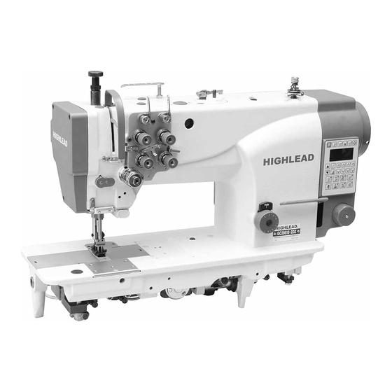
- Page 1 GC20618-1DZ/-2DZ Direct Drive Heavy Duty Compound Feed Lockstitch Sewing Machine With Automatic Thread Trimmer Instruction Manual Parts Catalog SHANGHAI BIAOZHUN HAILING SEWING MACHINERY CO.,LTD.
-
Page 2: Table Of Contents
——CONTENTS —— PRECAUTIONS BEFORE STARTING OPERATION ································································ 1 SPECIFICATIONS ···························································································································· 1 LUBRICATION ································································································································· 2 PRECAUTIONS OPERATION ······································································································· 2 ADJUSTMENT OF NEEDLE BAR STOP POSITION ································································ 2 INSTALLING NEEDLE ··················································································································· 3 WINDING BOBBIN THREAD ········································································································ 3 SELECTION OF THREAD ·············································································································· 3 THREADING ·····································································································································... -
Page 3: Precautions Before Starting Operation
3) Precautions for operating conditions: (1)Avoid using the machine at abnormally high temperatures(35 ℃ )or low temperatures(5 ℃ or higher or lower). (2)Avoid using the machine in dusty conditions. 2.SPECIFICATIONS Model GC20618-1DZ GC20618-2DZ Max.sewing speed 2500r.p.m Stitch length By hand Presser-foot stroke By pneumatic... -
Page 4: Lubrication
3.LUBRICATION 1) Oiling(1) Fill the oil reservoir with oil up to“H”mark.Oil level should periodically checked. If oil level is found below“L”level replenish oil to“H”level. Use white spindle oil. 2) Oiling(2) When sewing machine is used for the first time,or sewing machine left out of use for considerably long time is used again,replenish a suitable amount of oil to the portions indicated by arrow in the below figure. -
Page 5: Installing Needle
follows: Release the set screw of the magnet positioned piece, adjust the position of magnet positioning piece, until the machine stops in the needle up position (the marker on the pulley and the reference line of motor cover to coincide), then tighten the screws. 6.INSTALLING NEEDLE Note:Before installing... -
Page 6: Threading
right needle.When discriminate use “Z”twist thread in both the needles.For bobbin thread,”S”twist thread as well as “Z”twist thread can be used. 9.THREADING (1)Pass each thread through thread guide A. Note: When thin slippery thread (polyester thread) is used pass the thread through thread guide B as show in figure. -
Page 7: Lifting The Bobbin Thread
(2)Hold the bobbin so that the bobbin thread is would in right direction and put it into the hook. 12.LIFTING THE BOBBIN THREAD (1)Put the hook into the bobbin case and press down the latch 1. The thread end should be left on the bed. (2)While holding the thread by left hand,rorate the balance wheel one turn by right hand. -
Page 8: Adjustment Of Presser Foot Pressure
To adjust needle thread tension,turn each tension adjusting nut. Needle thread tension can be also adjusted for special fabric and thread by changing intensity and movable range of slack thread adjusting spring. 15.ADJUSTMENT OF PRESSER FOOT PRESSURE Pressure of presser foot is to be adjust in accordance with thickness of materials to be sewn. First loosen lock nut.For heavy materials,turn the adjust bolt to increase the pressure,while for light materials,turn the adjust bolt to decrease the pressure as shown in Fig. -
Page 9: Adjustment Of Feed Dog Height
(3)Approximate position of hook “C”screw of hook should be found close to the needle when the needle is at DOWN position. To finely adjust timing between the needle motion and hook motion,loosen the set screw of large gear and move the hook saddle in lower shaft axial direction within a rang from 1mm to 2mm. 17.ADJUSTMENT OF FEED DOG HEIGHT Height of feed dog and pressure of presser foot should be adjusted for individual fabric(s) with the following cautions:... -
Page 10: Motion
motion and take-up lever motion should be adjusted as follows: (1)Turn the balance wheel and stop when the take-up lever is lifed to its upper dead point. (2)Lean the machine head backward and make sure the arrow(timing mark)put on the timing belt is in line with the black line on the boss of lower shaft. -
Page 11: Safety Clutch Device
21.SAFETY CLUTCH DEVICE Safety clutch device is installed to prevent the hook and cog belt from damage in case the thread is caught into the hook when the machine is loaded abnormally during operation. 1) Function of safety clutch (1)When the safety clutch acts,the belt pulley will be unloaded,then the rotation of hook shaft will stop.The arm shaft only will rotate.Stop the operation of machine. -
Page 12: Walking Foot And Presser Foot Vertical Stroke Adjustment
(2)Move the bolt upward to increase upper feed. (3)Move the special bolt downward to decrease the upper feed.The upper feed and the lower feed theoretically becomes equal at the reference line on the feed connection crank(right). Securely tighten the bolt after adjustment 23.WALKING FOOT AND PRESSER FOOT VERTICAL... -
Page 13: Adjustment Of Thread Trimmer Cam
balance wheel.Set the cam follower crank at this position with a screwdriver temporarily preventing the cam roller coming out from the cam groove. (4)Loosen the thread trimmer rocking crank clamp bolts A and B. (5)Adjust the movable knife so that the movable knife end slant portion protrudes 0-0.5mm from the fixed knife,as shown in figure and tighten the bolts A and B. -
Page 14: Adjustment Of Scissoring Pressure Of Movable Knife And Fixed
Note:To adjust,loosen two thread trimmer cam clamp screws A. 27.ADJUSTMENT OF SCISSORING PRESSURE OF MOVABLE KNIFE AND FIXED KNIFE (1)Loosen the fixed knife bracket clamp bolt A. (2)Turn the vertical position adjusting screw B to adjust meshing pressure and then righter the hexagon socket head cap screw A. -
Page 15: Specifications Of The Operation Panel
(4)Remove the spring M. (5)Loosen the hook bracket clamp screws A and B and adjust gap between each needle and hook. (6)When the needles and hooks have been adjusted, install the spring M. (7)Contact the rocking cranks C and D to the stopper pins E and F and tighten the connecting link clamp bolt J. -
Page 16: Valve Complete
31.VALVE COMPLETE This machine is designed with mini valve complete that installed integrately by several valves.For single needle model is 5 valves,and the two needle model is 4 valves.The function of the valves as shown in Fig.(Left: standard control system.Right :integrated control system) A. - Page 17 A.ARM BED AND ITS ACCESSORIES — 15 — — 15 —...
- Page 18 A.ARM BED AND ITS ACCESSORIES Fig. Part No. Name Description Oil guard H2400B2050 Plate for oil guard H2400B2060 Rubber plug HA300B2090 Φ8.8 Rubber plug H4715B8001 Φ13 Thread take-up cover H4717B8001 Screw HA300B2170 Side cover(left) HFB1138001 Rubber plug H4735B8001 Φ24 Bobbin thread winder HFD1137101 Screw H3107G0662...
- Page 19 A.ARM BED AND ITS ACCESSORIES Fig. Part No. Name Description Cover plate H5015B8001 Screw HA100C2190 SM11/64(40)×8 Electric line holder HFB0188001 Face plate HFB1118001 Thread guide HA106B0675 Screw HA106B0676 SM9/64(40)×6 Screw H3000D2160 SM9/64(40)×7 Thread guide H4726B8001 — 17 —...
- Page 20 B.THREAD TENSION REGULATOR MECHANISM — 18 — — 18 —...
- Page 21 B.THREAD TENSION REGULATOR MECHANISM Fig. Part No. Name Description Handlebar HFC1168001 H003002050 Thread tension stud HFC1208001 Mounting plate HFC1108001 Washer HFC1148001 Thread guide plate HF930C8001 Thread tension stud HFC1218001 Thread tension plate HA112B0693 Thread tension spring HA710B0672 Thread tension nut HA710B0671 Thread tension stud H3221B0689...
- Page 22 B.THREAD TENSION REGULATOR MECHANISM Fig. Part No. Name Description Thread guide H3306B0661 Screw HA300C2030 SM11/64(40)×8 Air cylinder HFC1048001 ACQ 10×1.5-SJ2673E Screw H415030100 Screw H34411C410 — 20 —...
- Page 23 C.ARM SHAFT MECHANISM — 21 — — 21 —...
- Page 24 C.ARM SHAFT MECHANISM Fig. Part No. Name Description Screw HA108C0663 SM1/4(40)×7 Crank H4706D8001 Screw HA105D0662 SM1/4(40)×4 Screw HA100C2060 SM9/32(28)×13 Screw HA100C2070 SM9/32(28)×14 Arm shaft bushing(left) H32111B204 Screw H2405D0664 SM15/64(28)×14 Oil felt H32111B104 Oil wick H4713E8001 Oil holder H20111C106 Bushing HY91B28001 Screw H3416D0692 SM15/64(28)×8...
- Page 25 C.ARM SHAFT MECHANISM Fig. Part No. Name Description Lifting presser foot H3100G2110 Finger guard HE013N8001 Finger guard HE204I8001 Screw H3200E2020 Screw H2405D0664 SM15/64(28)×14 Lifter plate HFE1178001 Screw Screw HA107H0662 Lifter plate HFE1168001 Lifter lever HFE1188001 Lifter cam HFE1068001 Lifter lever H3208E0672 Screw HA100B2110...
- Page 26 D.PRESSER FOOT MECHANISM — 24 — — 24 —...
- Page 27 D.PRESSER FOOT MECHANISM Fig. Part No. Name Description Adjust bolt HFE1098001 SM1/2(28)×35.5 HA117H0692 Bushing HFE1148001 Screw HA3411D308 SM15/64(28)×7 Presser spring HFE1128001 Guide bushing HFE1108001 Spring HFE1138001 Spring guide bushing HFE1118001 Guide bracket HFE1428001 E-type ring H007013040 Shaft pin HFE1448001 Shaft pin HFE1298001 Oil wick HFE1308001...
- Page 28 D.PRESSER FOOT MECHANISM Fig. Part No. Name Description Bolt H2000J2100 Guide pin HFE1418001 Bearing HE049C8002 NTN DCL 168 — 26 —...
- Page 29 E.NEEDLE BAR & THREAD TAKE-UP LEVER MECHANISM — 27 — — 27 —...
- Page 30 E.NEEDLE BAR & THREAD TAKE-UP LEVER MECHANISM Fig. Part No. Name Description Needle bar HFF1078001 Needle bar HFF0078001 Taper pin H602040240 Needle bar bracket HFF1098001 Screw H32111D304 Spacer HFF1168001 Needle bar vibrating shaft H3204D0652 Square block H32111D804 Screw HA110D0672 Screw H32111D604 SM9/64(40)×8.5 Bushing...
- Page 31 F.STITCH REGULATOR MECHANISM — 29 — — 29 —...
- Page 32 F.STITCH REGULATOR MECHANISM Fig. Part No. Name Description Feed regulator cam H4706G8001 Screw HA113F0684 Screw H3200F2020 Link H4707G8001 Eccentric shaft HA100G2070 Reverse stitch shaft H4909G8001 Reverse stitch shaft HFG0058001 Screw H4941L8001 Link H4948L8001 Screw HA800F2020 Crank H4905G8001 H4940L8001 Screw H415050150 Joint H662IE8001 PH4-M5...
- Page 33 F.STITCH REGULATOR MECHANISM Fig. Part No. Name Description Screw bar HA109F0671 Stopper pin HA700F2030 Spring H3200F2110 H3206F0662 Screw H428050060 Reverse sewing crank H4714G8001 Screw H415050140 Collar H4716G8001 Felt H4719G8001 Felt H4721G8001 Square block H4722G8001 Guide plate H4723G8001 Screw HA300C2030 Reverse block H4720G8001 —...
- Page 34 G.LOWER SHAFT & FEED ROCK SHAFT MECHANISM — 32 — — 32 —...
- Page 35 G.LOWER SHAFT & FEED ROCK SHAFT MECHANISM Fig. Part No. Name Description Lower shaft bushing(left) H4706H8001 Oil wick H4707H8001 Lower shaft H4708H8001 Feed lifting cam H4710H8001 Screw H3205H0654 SM1/4(40)×5 Lower shaft bushing(right) H4712H8001 Oil wick H4713H8001 E-type ring H007013050 Push button H4715H8001 Spring H4714H8001...
- Page 36 G.LOWER SHAFT & FEED ROCK SHAFT MECHANISM Fig. Part No. Name Description Collar HA108G0661 Screw HA105D0662 Feed connection crank(middle) H4736H8001 Feed rock shaft H3204G0651 Felt H3204G0652 Screw HA104G0012 Feed connection crank(left) H4905H8001 Oil wick H3204G0031 Clip H3200G2030 Screw H3200H2040 Washer H2013J0065 Screw H429030140...
- Page 37 H.HOOK SADDLE MECHANSIM — 35 — — 35 —...
- Page 38 H.HOOK SADDLE MECHANSIM Fig. Part No. Name Description Hook saddle H4906I8001 Screw H3207I0661 SM15/64(28)×22 Bushing H3207I0662 Screw H3204I6510 Hook gear(large) H4706I8001 Screw HA307C0662 Screw HA105D0662 Hook gear(small) H4705I8001 Bobbin H4912I8001 BO-B872(A) Spring H4922I8001 Hook complete H4908I7101 KRT12-5LMKC-C1 Oil wick H3204I0656 Opener bracket shaft H32153I504 Screw...
- Page 39 I.THREAD TRIMMER MECHAISM (Ⅰ) — 37 — — 37 —...
- Page 40 I.THREAD TRIMMER MECHAISM (Ⅰ) Fig. Part No. Name Description Screw H4905J8001 Screw H4906J8001 SM11/64(40)×12 Trimming knife holder H4907J8001 Screw HA7121N304 SM9/64(40)×4 Fixed knife H4909J8001 Fixed knife HEJ4078001 Screw H4914B8001 SM9/64(40)×4 Moved knife H4911J8001 Screw H4912J8001 SM1/8(44)×9.2 Screw H4913J8001 SM9/64(40)×4.5 Spring plate H4914J8001 Screw H4915J8001...
- Page 41 J.THREAD TRIMMER MECHAISM (Ⅱ) — 39 — — 39 —...
- Page 42 J.THREAD TRIMMER MECHAISM (Ⅱ) Fig. Part No. Name Description Connection crank H4912K8001 Screw H4913K8001 Spring H4945K8001 Crank H4908K8001 Screw H4907K8001 Link H4906K8001 Screw H4905K8001 Spring pin HA100H2080 Spring H4943K8001 Vibrating crank H4957K7101 Screw H4944K8001 Screw H431050050 Screw HA104F0654 Collar H4931K8001 Link H4909K8001 Washer...
- Page 43 J.THREAD TRIMMER MECHAISM (Ⅱ) Fig. Part No. Name Description HA7111N304 Solenoid complete HFK1087101 H4934K8001 Screw H431050050 — 41 —...
- Page 44 K.MOTOR MECHANISM — 42 — — 42 —...
- Page 45 K.MOTOR MECHANISM Fig. Part No. Name Description Touch switch complete HFL1187101 Screw HD15B58001 Screw HA100C2190 SM11/64(40)×8 Nylon holder HA708P0668 Screw H415050200 Direct drive motor HFL1088001 Motor cover HFL1138001 Screw H415050800 Screw H3416D0692 SM15/64(28)×8 Screw H7206E8001 SM15/64(28)×6 Pulley complete HFL1057101 Operation panel HFL1147101 Electronic dial HFL1217101...
- Page 46 L.OIL LUBRICATION MECHANISM — 44 — — 44 —...
- Page 47 L.OIL LUBRICATION MECHANISM Fig. Part No. Name Description Felt H32175B304 Oil pipe complete H4705J7101 Oil reservoir complete H3204K0011 Screw H411040160 Oil pipe holder H4707J8001 Oil pipe Ф3×1×500 HFM1068001 Oil pipe Ф5×1×450 HFM1078001 Oil pipe complete H4711J7101 Spring H4710J8001 Screw HA7311CC06 Washer HA100I2050 Oil pipe holder...
- Page 48 L.OIL LUBRICATION MECHANISM Fig. Part No. Name Description Oil pipe complete H4728J7101 Oil pipe holder HD15J98001 — 46 —...
- Page 49 M.ACCESSORIES — 47 — — 47 —...
- Page 50 M.ACCESSORIES Fig. Part No. Name Description Thread a needle kit H3207L0065 Needle DP×17 21# Socket wrench HB00001030 Socket wrench HB00001020 Bobbin H4912I8001 Vibration preventing rubber H4700K0020 Vibration preventing rubber H4700K0030 Screw drive(small) HA300J2210 Screw drive(large) HA300J2070 Oiler HA100J2110 Thread guide HFN1177101 Thread stand H3200L0120...
- Page 51 N.INTEGRATED DIRECT DRIVE AND CONTROL — 49 — — 49 —...
- Page 52 N.INTEGRATED DIRECT DRIVE AND CONTROL Fig. Part No. Name Description Touch switch complete HFL5157101 Screw H5731B8001 Cover HFB5158001 Valve complete Valve complete Screw H409050080 Valve fixed plate HFO5088001 Screw H415040120 Valve fixed plate HFO5098001 Screw H415040200 Screw HFL5148001 Electric plate HFL5128001 Protection paper HFL5118001...
- Page 53 SHANGHAI BIAOZHUN HAILING SEWING MACHINERY CO.,LTD. ADD: No.850 Shulin Road, Songjiang District,Shanghai, P.R.China Zip Code: 201612 Overseas Business: TEL: 86-21-64853303 FAX: 86-21-64854304 E-mail:sales@highlead.com.cn http://www.highlead.com.cn The description covered in this manual is subject to change for improvement of the commodity without notice 2016.10. Printed...
Need help?
Do you have a question about the GC20618-1DZ and is the answer not in the manual?
Questions and answers