Table of Contents
Advertisement
Available languages
Available languages
Quick Links
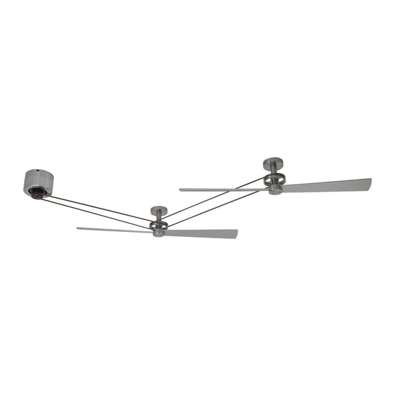
The Kellan
Belt-Driven Ceiling Fans
Suitable for use with Solid State Speed Controls
WARNING: Support Directly From Building Structure For Fan Head Assembly
Model No. MA7966 Motor Series
Model No. HA7966 Fan Series
Model No. B7966 Fan Blade
OWNER'S MANUAL
READ AND SAVE THESE INSTRUCTIONS
MA7966 Net Weight 9.3 kg (20.48 lbs)
HA7966 Net Weight 2.4 kg (5.29 lbs)
B7966 Net Weight 0.60 kg (1.32 lbs)
FP7966
™
Advertisement
Chapters
Table of Contents

Related Manuals for Fanimation MA7966


Summary of Contents for Fanimation MA7966
- Page 1 The Kellan ™ Belt-Driven Ceiling Fans MA7966 Net Weight 9.3 kg (20.48 lbs) HA7966 Net Weight 2.4 kg (5.29 lbs) B7966 Net Weight 0.60 kg (1.32 lbs) Suitable for use with Solid State Speed Controls WARNING: Support Directly From Building Structure For Fan Head Assembly FP7966 Model No.
-
Page 2: Important Safety Instructions
1. LIMITED LIFETIME MOTOR WARRANTY - If any part of your fan motor fails, due to a defect in materials or workmanship during the lifetime of the original purchaser, Fanimation will provide the replacement part free of charge, when the defective fan is returned to our national service center. -
Page 3: Table Of Contents
Exploded-View, Motor Assembly MA7966 ........ -
Page 4: Motor Assembly-Unpacking Instructions And Parts Identification
Fanimation. Substitution of parts or accessories not Wood Screw designated for use with this product by Fanimation could Rivet Tool – Five #10 Type B Flat Washer result in personal injury or property damage. Contact Punch Tool –... -
Page 5: Head Assembly-Unpacking Instructions And Parts Identification
Head Assembly—Unpacking Instructions and Parts Identification 1. Check to see that you have received the following parts: Belt washer head screws HA7966 Head Assembly and Hardware Parts Identification Pilot Hole Paper Pulley Assembly Belt Hardware bag NOTE: The illustration shown is not to scale or its actual con guration may vary. Parts and packings subject to change without notice. -
Page 6: Energy Efficient Use Of Ceiling Fans
8 - 9 feet above the floor for optimal airflow. Consult your down into the occupied space.Remember to adjust your Fanimation Retailer for optional mounting accessories. thermostat when using your ceiling fan - additional energy and dollar savings could be realized with this simple step! Turn Off When Not in the Room Ceiling fans cool people, not rooms. -
Page 7: Figures
Electrical and Structural Requirements (Continued) Deep box with brace (Figure 3) Paired with a deep box, this hanger is meant to span CEILING JOIST between two joists and takes the place of wooden blocking. WARNING To reduce the risk of fire, electric shock, or personal injury, mount to outlet box marked acceptable for fan support of 15.9 kg (35 lbs) or less and use mounting screws provided with the outlet box and/or support... -
Page 8: How To Hang And Wire Your Motor Assembly
How to Hang and Wire Your Motor Assembly WARNING Ceiling The fan must be hung with at least 7´ of clearance from floor to blades. (Figure 1) WARNING To avoid possible electrical shock, be sure electricity is turned off at the main fuse box before hanging. less than NOTE: If you are not sure if the outlet box is grounded, 7 ft... -
Page 9: Figure
How to Hang and Wire Your Motor Assembly (continued) If you feel that you do not have enough electrical wiring knowledge or experience, have your fan installed by a licensed electrician. 4. IMPORTANT- If driving two, three or four head assemblies with motor, make sure four-pin and two-pin connectors are connected in the motor assembly. - Page 10 How to Hang and Wire Your Motor Assembly (continued) 7. Assemble the motor assembly to ceiling plate assembly using the previously removed hex nuts and flat washers and securely tighten all hex nuts. (Figure 8) Figure 8 8. Assemble the housing to ceiling plate assembly using the previously removed screws and securely tighten all screws.
-
Page 11: How To Hang Your Head Assembly
How to Hang Your Head Assembly 1. Remove the four screws from the pulley assembly mounting cover by using the supplied allen wrench. Retain the screws for reinstallation in Step 4. (Figure 1) Pulley Assembly Mounting Cover Allen Wrench Figure 1 HARDWARE USED: ALLEN WRENCH... -
Page 12: Belt Splicing Instructions
Belt Splicing Instructions 1. Wrap the belting around the two pulleys that will be connected and overlap the belting as shown. Use the spring clamps provided to hold the belting in place temporarily. With the clamps remaining in the same place, grasp both ends of the belting and pull tight. -
Page 13: How To Mount The Fan Blades
How to Mount the Fan Blades 1. To adjust the vertical alignment of the belt, loosen the screw in the pulley assembly pulley with the supplied by Pulley allen wrench to adjust the pulley so that belt is parallel Motor Assembly with the floor, then securely tighten the screw. -
Page 14: How To Set Up Your Tr33Wh Remote Control
How to Set Up Your TR33WH Remote Control IMPORTANT: Using a full range dimmer switch (not included) to control fan speed will damage the fan. To reduce the risk of fire or electrical shock, do not use a full range dimmer switch to control the fan speed. (Figure 1) For illustrative purposes only-not Setting the Code: The remote unit has 16 different... -
Page 15: How To Mount Your Remote Control
How to Mount Your Remote Control (Option #1) 1. Unthread two screws from the wall switch plate. (Figure 1) 2. Install the control bracket with two #6-32x 3/4” screws. And push the four plastic plug to cover the screw holes. (Including in the control).(Figure 2) Figure 1 Figure 2... -
Page 16: Maintenance
Maintenance Periodic cleaning of your new ceiling fan is the only CAUTION maintenance that is needed. When cleaning, use only a soft brush or lint free cloth to avoid scratching the nish. Do not use water when cleaning your ceiling fan. It could damage the motor or the blades and create the Abrasive and/or non-abrasive cleaning agents are not possibility of electrical shock. - Page 17 Motor Assembly MA7966** Exploded-View Figure 1 Insert FINISH CODES (Refer to fan model number located on fan assembly) NOTE: The illustration shown is not to scale or its actual configuration may vary. Wires partially removed for clarity.
-
Page 18: Parts List Motor Assembly Ma7966
Parts List Motor Assembly MA7966** Ref. # Description Part # Rivet Tool Hand Held Remote TR33WH Receiver Harness Wiring-Capacitor Hardware Bags Containing: Insert FINISH CODES (Refer to fan model number located on downrod support) Before discarding packaging materials, be certain all parts have been removed How To Order Parts Contact your retail store for repair parts. - Page 19 Head Assembly HA7966** Exploded-View Figure 2 Parts List Ref. # Description Part # Belt Hardware Bags Containing: Lag Bolt 1/4 x 2 (5) Ø Ø Blade Mount Hardware Bag Containing: Washer Blade Optional Ref. # Description Part # Blade Before discarding packaging materials, be certain all parts have been removed How To Order Parts Contact your retail store for repair parts.
- Page 20 10983 Bennett Parkway Zionsville, IN 46077 Toll Free (888) 567-2055 FAX (866) 482-5215 Outside U.S. call (317) 733-4113 Visit Our Website www.fanimation.com Copyright 2014 Fanimation 2014/09 V.01...
- Page 21 Apropiado para su uso con controles de velocidad de estado sólido ADVERTENCIA: Soporte directamente desde la estructura del edificio para el unidad del cabezal. FP7966 Modelo N.º MA7966 Unidad del motor Modelo N.º HA7966 Unidad del cabezal Modelo N.º B7966 Juego de aspas...
- Page 22 GARANTÍA LIMITADA DE POR VIDA DEL MOTOR - Si se produjera una falla en alguna de las partes del motor de su ventilador debido a un defecto en los materiales o en la fabricación durante el tiempo de vida del comprador original, Fanimation proporcionará la pieza de repuesto sin cargo una vez que el ventilador defectuoso sea devuelto a nuestro centro de servicios nacional.
- Page 23 Ilustración del despiece, unidad del motor de MA7966 ....... .
-
Page 24: Unidad Del Motor-Instrucciones De Desembalaje E Identificación De Las Piezas
Póngase en contacto con su tienda si faltan piezas o hay piezas dañadas. Unidad del motor del MA7966 y identificación de las piezas del equipo Unidad de placa para el techo Mano a distancia... -
Page 25: Unidad Del Cabezal-Instrucciones De Desembalaje E Identificación De Las Piezas
Unidad del cabezal-Instrucciones de desembalaje e identificación de las piezas 1. Verifique que haya recibido las siguientes piezas: Unidad del polea Bolsas de accesorios: Correa – Siete tornillos de cabeza de – Cinco arandela plana de Ø6.5 x Ø16 x 1 mm Papel piloto para orificio –... -
Page 26: Requisitos Eléctricos Y Estructurales
óptimo. del reloj. Esto produce una suave corriente ascendente, Consulte en su tienda minorista de Fanimation para que obliga al aire cálido que se acumula cerca del techo a obtener accesorios de montaje opcionales. - Page 27 Requisitos eléctricos y estructurales (cont.) Profunda caja con aparato ortopédico (Figura 3) Vigas del Conectado a una caja de distribución eléctrica, este colgador techo sirve para abarcar el espacio entre dos vigas y ocupar el lugar de bloqueo de la madera. ADVERTENCIA Para reducir el riesgo de incendio, descargas eléctricas o lesiones personales, monte el ventilador en una caja de...
-
Page 28: Cómo E
Cómo instalación y cableado del ventilador de techo ADVERTENCIA EI Techo Las aspas del ventilador deben estar suspendidas, al menos, a 2 m (7´) del piso (Figura 1) ADVERTENCIA Para evitar posibles descargas eléctricas, asegúrese de que la electricidad esté desconectada en la caja de menos de fusibles principal antes de colgar el ventilador. - Page 29 Cómo instalación y cableado del ventilador de techo (cont.) Si considera que no cuenta con la experiencia o los conocimientos eléctricos necesarios, contrate a un electricista autorizado para instalar el ventilador. 4. IMPORTANTE- Si conecta dos, tres o cuatro unidades de cabezales con motor, asegúrese de Conector de 2 que los conectores de dos y cuatro pines están pines individuales...
- Page 30 Cómo instalación y cableado del ventilador de techo (cont.) 7. Instale la unidad del motor a la Unidad de placa para el techo de techo utilizando las tuercas hexagonales y arandelas planas anteriormente extraídas y fíjelas adecuadamente. (Figura 8) Figura 8 8.
-
Page 31: Cómo Colgar La Unidad Del Cabezal
Cómo colgar la unidad del cabezal 1. Extraiga los cuatro tornillos de la carcasa de montaje de la unidad del polea utilizando la llave de Allen suministrada. Guarde los tornillos para su reinstalación Carcasa de montaje en el paso 4. (Figura 1) de la unidad del polea Llave de Allen... -
Page 32: Instrucciones Del Ensamblaje De La Correa
Instrucciones del ensamblaje de la correa 1. Enrolle la correa alrededor de las poleas para que quede conectada y esté montada en sí mismo como se muestra en la ilustración. Utilice las pinzas de muelles suministradas para mantener la correa en su sitio de forma temporal. Dejando las pinzas en el mismo sitio, agarre ambos extremos de la correa y tire con fuerza. -
Page 33: Cómo
Cómo montaje de las palas del ventilador 1. Para ajustar el alineamiento vertical de la correa, afloje el tornillo de la polea de la unidad del polea Unidad del polea con la llave Allen suministrada para ajustar dicha polea y conseguir que la correa esté en paralelo con Unidad de motor el suelo. -
Page 34: Cómo Configurar Su Mando A Distancia Tr33Wh
Cómo configurar su mando a distancia TR33WH IMPORTANTE: El uso de un regulador de la intensidad completa (no incluido) para controlar la velocidad del ventilador dañará el dispositivo. Para reducir el riesgo de incendio o descarga eléctrica, no utilice dicho regulador para controlar la velocidad del ventilador. -
Page 35: Cómo Instalar Su Mando A Distancia
Cómo instalar su mando a distancia ( Opción #1 1. Retire los dos tornillos colocados en la plaza del interruptor de la pared. (Figura 1) 2. Instale el soporte de control con los dos tornillos #6-32x 3/4”. Empuje los cuatro tapones de plástico para cubrir los orificios de los tornillos. -
Page 36: Mantenimiento
Mantenimiento PRECAUCIÓN El único mantenimiento necesario para el ventilador de techo es una limpieza periódica. Al llevar a cabo la limpieza, use sólo un cepillo suave o un No utilice solventes para limpiar el ventilador de techo. Podrían dañar el motor o las aspas y ocasionar posibles paño sin pelusas, para evitar rayar el acabado. - Page 37 Unidad del motor de MA7966** Ilustración del despiece Figura 1 Introduzcas los CÓDIGOS de acabo (Consulte el número de modelo del ventilador ubicado en la unidad del ventilador). NOTA:...
-
Page 38: Lista De Piezas Unidad Del Motor De Ma7966
Lista de piezas Unidad del motor de MA7966** N.º de ref. Descripción Pieza N.º Unidad de placa para el techo AP796601** Unidad del motor AMA7966BL Unidad del carcasa AP796603** Remachadora P128005 Perforadora P128010 Pinzas de la correa (2) P128015 Mano a distancia... - Page 39 Unidad del cabezal de HA7966** Ilustración del despiece Figura 2 Lista de piezas N.º de ref. Descripción Pieza N.º AP7966** Unidad del polea Correa BM30 Papel piloto para orificio P796617 Bolsas de accesorios: Arandela plana de Ø6.5 x Ø16 x 1 mm (5) Llave Allen de 6 x 90 x 32 mm HDWHA7966** Bolsa de accesorios para el montaje de soporte de aspas:...
- Page 40 10983 Bennett Parkway Zionsville, IN 46077 Llame sin cargo al (888) 567-2055 FAX (866) 482-5215 Desde fuera de los EE.UU., llame al (317) 733-4113 Visite nuestro sitio Web en www.fanimation.com Copyright 2014 Fanimation 2014/09 V.01...