Table of Contents
Advertisement
Available languages
Available languages
Quick Links
R
PORTABLE
FORCED
AIR HEATERS
OWNER'S MANUAL
Heater Sizes: 35,000 70,000 100,000 150,000 Btu/Hr
Models: B35CEA, B70CEA, B100CEA, and B150CEA
IMPORTANT: Read and understand this manual before assembling, starting or
servicing heater. Improper use of heater can cause serious injury. Keep this manual
for future reference.
Advertisement
Table of Contents

Related Manuals for Master Lock B100CEA


Summary of Contents for Master Lock B100CEA
- Page 1 AIR HEATERS OWNER’S MANUAL Heater Sizes: 35,000 70,000 100,000 150,000 Btu/Hr Models: B35CEA, B70CEA, B100CEA, and B150CEA IMPORTANT: Read and understand this manual before assembling, starting or servicing heater. Improper use of heater can cause serious injury. Keep this manual...
-
Page 2: Safety Information
PORTABLE FORCED AIR HEATERS SAFETY INFORMATION WARNINGS IMPORTANT: Read this Owner’s Manual carefully and completely before trying to assemble, oper- ate, or service this heater. Im- proper use of this heater can cause serious injury or death from burns, fire, explosion, electrical shock, and carbon monoxide poisoning. -
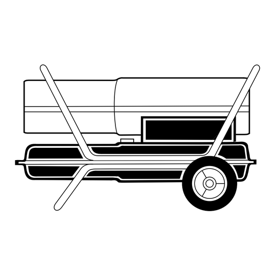
Page 3: Product Identification
PRODUCT IDENTIFICATION Hot Air Outlet Upper Shell Lower Shell Fuel Tank Side Cover Flame-Out Control Reset Button Power Cord Figure 1 - 35/70,000 Btu/Hr Models Hot Air Outlet Lower Shell Fuel Cap Side Cover Figure 2 - 100/150,000 Btu/Hr Models 104468 OWNER’S MANUAL Handle... - Page 4 PORTABLE FORCED AIR HEATERS ASSEMBLY (FOR 100,000 AND 150,000 BTU/HR MODELS ONLY) These models are furnished with wheels and handles. Wheels, handles, and the mounting hardware are found in the shipping carton. Tools Needed • Medium Phillips Screwdriver • 3/8" Open or Adjustable Wrench •...
-
Page 5: Theory Of Operation
THEORY OF OPERATION The Fuel System: The air pump forces air through the air line. The air is then pushed through the burner head nozzle. This air causes fuel to lift from the tank. A fine mist of fuel is sprayed into the combustion chamber. -
Page 6: Storing, Transporting, Or Shipping
PORTABLE FORCED AIR HEATERS STORING, TRANSPORTING, OR SHIPPING Note: If shipping, transport companies re- quire fuel tanks to be empty. 1. Drain fuel tank. Note: Some models have drain plug on underside of fuel tank. If so, remove drain plug to drain all fuel. If heater does not have drain plug, drain fuel through fuel cap opening. -
Page 7: Troubleshooting
TROUBLESHOOTING OBSERVED FAULT Heater ignites, but flame-out control shuts off heater after a short period of time. Heater will not ignite, but motor runs for a short period of time. Motor does not start when heater is plugged in, fan rotates slowly or does not turn. 104468 OWNER’S MANUAL WARNING: Never service heater while it is plugged in, operating,... -
Page 8: Upper Shell Removal
PORTABLE FORCED AIR HEATERS SERVICE PROCEDURES WARNING: Never service heater while it is plugged in, op- erating, or hot. Severe burns and electrical shock can occur. Upper Shell Removal Remove screws and lock washers along each side of heater using 5/16" nut- driver. - Page 9 SERVICE PROCEDURES Continued Spark Plug (35,000 Btu/Hr Model) 1. Remove upper shell (see page 8). 2. Remove fan (see page 13). 3. Remove fuel and air line hoses from nozzle assembly. 4. Remove spark plug wire from spark plug. 5. Remove two screws using 5/16" nut- driver and remove burner strap.
-
Page 10: Pump Pressure Adjustment
PORTABLE FORCED AIR HEATERS SERVICE PROCEDURES Continued Air Output, Air Intake, and Lint Filters 1. Remove upper shell (see page 8). 2. Remove filter end cover screws using 5/16" nut-driver. 3. Remove filter end cover. 4. Replace air output and lint filters. 5. - Page 11 SERVICE PROCEDURES Continued Nozzle (35,000 Btu/Hr Model) 1. Remove upper shell (see page 8). 2. Remove fan (see page 13). 3. Remove fuel and air line hoses from nozzle assembly. 4. Turn nozzle assembly 1/4 turn to left and pull toward motor to remove. 5.
- Page 12 PORTABLE FORCED AIR HEATERS SERVICE PROCEDURES Continued Pump Rotor (Procedure if rotor is binding) 1. Remove upper shell (see page 8). 2. Remove filter end cover screws using 5/16" nut-driver. 3. Remove filter end cover and air filters. 4. Remove pump plate screws using 5/16" nut-driver.
-
Page 13: Specifications
SERVICE PROCEDURES Continued IMPORTANT: Remove fan from motor shaft before removing motor from heater. The weight of the motor resting on the fan could damage the fan pitch. 1. Remove upper shell (see page 8). 2. Use 1/8" allen wrench to loosen set- screw which holds fan to motor shaft. -
Page 14: Illustrated Parts Breakdown
PORTABLE FORCED AIR HEATERS ILLUSTRATED PARTS BREAKDOWN 35,000 BTU/HR 18-1 18-2 18-18 18-4 18-3 18-17 18-16 18-15 18-14 Motor and Pump Assembly 18-5 18-6 18-7 18-8 18-9 18-10 18-11 18-12 18-13 11-5 11-4 11-1 11-2 11-3 14 10 104468... -
Page 15: Parts List
PARTS LIST 35,000 BTU/HR PART PART NUMBER DESCRIPTION M51104-01 Handle 098511-54 Upper Shell 102432-01 Screw/Lockwasher, 1/2" 098512-43 Combustion Chamber M51108-01 Heat Shield M11084-29 Screw, #10-16 x 3/4" M16660 Photocell Bracket M10908-2 Screw, #6-32 x 3/8" HA3019 Photocell Assembly 079673-06 Power Cord Burner Strap Assembly 11-1 097124-01... - Page 16 PORTABLE FORCED AIR HEATERS ILLUSTRATED PARTS BREAKDOWN 70,000 BTU/HR Burner Head Assembly 10-1 10-2 10-4 10-5 10-3 10-7 10-6 18-1 18-2 18-18 18-4 18-3 18-17 18-16 18-15 18-14 Motor and Pump Assembly 18-5 18-6 18-7 18-8 18-9 18-10 18-11 18-12 18-13 104468...
- Page 17 PARTS LIST 70,000 BTU/HR PART PART NUMBER DESCRIPTION M51104-01 Handle 098511-54 Upper Shell 102432-01 Screw/Lockwasher, 1/2" 098512-44 Combustion Chamber M11084-29 Screw, #10-16 x 3/4" M16660 Photocell Bracket M10908-2 Screw, #6-32 x 3/8" HA3019 Photocell Assembly 079673-06 Power Cord Burner Head Assembly 10-1 HA3008 Nozzle...
- Page 18 PORTABLE FORCED AIR HEATERS ILLUSTRATED PARTS BREAKDOWN 100,000 BTU/HR Burner Head Assembly 13-1 13-3 13-2 13-4 13-18 13-17 13-16 13-15 13-14 Motor and Pump Assembly 13-5 13-6 13-7 13-8 13-9 13-13 13-12 13-10 13-11 104468...
- Page 19 PARTS LIST 100,000 BTU/HR PART PART NUMBER DESCRIPTION 098511-138 Upper Shell 102432-01 Screw/Lockwasher, 1/2" 098512-31 Combustion Chamber M16660 Photocell Bracket HA3019 Photocell Assembly M27417 Drain Plug M10908-2 Screw, #6-32 x 3/8" Burner Head Assembly 100735-15 Nozzle M10659-1 Nozzle Seal Washer M10809-1 Nozzle Seal Spring M8882...
- Page 20 PORTABLE FORCED AIR HEATERS ILLUSTRATED PARTS BREAKDOWN 150,000 BTU/HR Burner Head Assembly 13-1 13-3 13-2 13-4 13-18 13-17 13-16 13-15 13-14 Motor and Pump Assembly 13-5 13-6 13-7 13-8 13-9 13-13 13-12 13-10 13-11 104468...
- Page 21 PARTS LIST 150,000 BTU/HR PART PART NUMBER DESCRIPTION 098511-138 Upper Shell 102432-01 Screw/Lockwasher, 1/2" 098512-36 Combustion Chamber 099229-01 Photocell Bracket HA3019 Photocell Assembly M27417 Drain Plug M10908-2 Screw, #6-32 x 3/8" Burner Head Assembly 100735-11 Nozzle M10659-1 Nozzle Seal Washer M10809-1 Nozzle Seal Spring M8882...
-
Page 22: Wheels And Handles
PORTABLE FORCED AIR HEATERS WHEELS AND HANDLES 100,000 AND 150,000 BTU/HR MODELS KEY PART PART NO. NUMBER DESCRIPTION HA2203 Handles HA2204 Handles M12345-33 Screw, #10-24 x 1 3/4" M12342-3 Wheel Support Frame M12831-3 Wheel Support Frame NTC-3C Hex Nut, #10-24 097896-03 Wheel M28526... - Page 23 ACCESSORIES Purchase accessories from your local dealer. AIR GAUGE KIT - HA1180 For all models. Special tool to check pump pressure. HEAVY DUTY WHEELS AND HANDLE KIT - HA1202 For heavy duty applications. Makes your heater even more portable and convenient. For 35/70,000 Btu/Hr models.
-
Page 24: Warranty And Repair Service
WARRANTY AND REPAIR SERVICE EQUIPMENT - LIMITED 90 DAY WARRANTY DESA International warrants new Products sold by it to be free from defects in material or workmanship for a period of ninety days after date of delivery to the first user and subject to the following conditions: DESA International's obligation and liability under this Warranty is expressly limited to repairing or replacing at DESA... -
Page 25: Manual Del Propietario
MANUAL DEL PROPIETARIO Tamaños: 10,2 (35.000) 20,5 (70.000) 29,3 (100.000) 44 kW (150.000 Btu/hr) Modelos: B35CEA, B70CEA, B100CEA, Y B150CEA IMPORTANTE: Lea y comprenda este manual antes de armar, encender o dar servicio al calentador. El uso indebido del calentador puede causar lesiones graves. Guarde este manual para referencia futura. -
Page 26: Informacion De Seguridad
CALENTADORES PORTATILES DE AIRE FORZADO INFORMACION DE SEGURIDAD ADVERTENCIAS IMPORTANTE: Lea este manual del propietario detenida y com- pletamente antes de intentar ar- mar, usar o dar servicio al calen- tador. El uso indebido de este calentador puede causar lesio- nes graves o la muerte a causa de las quemaduras, incendios, explosiones, choques eléctricos... -
Page 27: Identificacion Del Producto
IDENTIFICACION DEL PRODUCTO Salida de aire caliente Casco superior Casco inferior Tanque de combustible Cubierta lateral Botón de reposición del control de extinción de llamas Figura 1 - Modelos de 10,2/20,5 kW (35.000/70.000 Btu/hr) Salida de aire caliente Casco inferior Tapa de combustible Cubierta... -
Page 28: Herramientas Necesarias
CALENTADORES PORTATILES DE AIRE FORZADO ARMADO (SÓLO PARA MODELOS DE 29,3 Y 44 KW [100.000 Y 150.000 BTU/HR]) Estos modelos se proveen con ruedas y asas. Las ruedas, asas y la tornillería de montaje se encuentran en la caja de embalaje. Herramientas necesarias •... -
Page 29: Teoria De Funcionamiento
TEORIA DE FUNCIONAMIENTO Sistema de combustible: La bomba de aire fuerza el paso del aire por la línea de aire. De allí, el aire es empujado a través de la boquilla del quemador. Este aire hace que el combustible del tanque suba. Un vapor fino de combustible es rociado en la cámara de combustión. -
Page 30: Almacenamiento, Transporte Oembarque
CALENTADORES PORTATILES DE AIRE FORZADO ALMACENAMIENTO, TRANSPORTE O EMBARQUE Nota: Si se está despachando la unidad para embarque, las compañías transportistas exi- gen que los tanques de combustible estén vacíos. Vaciar el tanque de combustible. Nota: Algunos modelos tienen el tapón de vaciado en el lado inferior del tan- que de combustible. -
Page 31: Localizacion De Averias
LOCALIZACION DE AVERIAS AVERIA OBSERVADA El calentador se enciende, pero el control de extinción de llamas lo apaga después de un rato corto. El calentador no enciende, pero el motor funciona por un rato corto. El motor no arranca al enchufar el calenta- dor, el ventilador gira lentamente o no gira. -
Page 32: Remoción Del Casco Superior
CALENTADORES PORTATILES DE AIRE FORZADO PROCEDIMIENTOS DE SERVICIO ADVERTENCIA: Nunca repa- re el calentador mientras está enchufado, en funcionamiento o caliente. Podrían ocurrir graves quemaduras y electrochoque. Remoción del casco superior 1. Quite los tornillos a lo largo de cada lado del calentador con una llave de tuercas de 5/16". -
Page 33: Procedimientos De Servicio
PROCEDIMIENTOS DE SERVICIO Continuación Bujía (Modelo de 10,2 kW [35,000 Btu/hr]) 1. Quite el casco superior (vea la página 8). 2. Quite el ventilador (vea la página 13). 3. Quite las mangueras de las líneas de aire y de combustible del conjunto de la boquilla. - Page 34 CALENTADORES PORTATILES DE AIRE FORZADO PROCEDIMIENTOS DE SERVICIO Continuación Filtros de salida de aire, de admisión de aire y de pelusa 1. Quite el casco superior (vea la página 8). 2. Quite los tornillos de la cubierta del extremo del filtro con una llave de tuercas de 5/16".
- Page 35 PROCEDIMIENTOS DE SERVICIO Continuación Boquilla (Modelo de 10,2 kW [35.000 Btu/hr]) 1. Quite el casco superior (vea la página 8). 2. Quite el ventilador (vea la página 13). 3. Quite las mangueras de las líneas de aire y de combustible del conjunto de la boquilla.
- Page 36 CALENTADORES PORTATILES DE AIRE FORZADO PROCEDIMIENTOS DE SERVICIO Continuación Rotor de la bomba (Procedimiento si el rotor se atasca) 1. Quite el casco superior (vea la página 8). 2. Quite los tornillos de la cubierta del extremo del filtro con una llave de tuercas de 5/16".
-
Page 37: Especificaciones
PROCEDIMIENTOS DE SERVICIO Continuación Ventilador IMPORTANTE: Quite el ventilador del eje del motor antes de quitar el motor del calen- tador. Si el peso del motor se apoya sobre el ventilador, se podría dañar el paso de las paletas del ventilador. 1. - Page 38 CALENTADORES PORTATILES DE AIRE FORZADO DESPIECE ILUSTRADO 10,2 KW (35.000 BTU/HR) 18-1 18-2 18-18 18-4 18-3 18-17 18-16 18-15 18-14 Conjunto de motor y bomba 18-5 18-6 18-7 18-8 18-9 18-10 18-11 18-12 18-13 11-4 11-5 11-1 11-2 11-3 14 10 104468...
-
Page 39: Lista De Piezas
LISTA DE PIEZAS 10,2 KW (35.000 BTU/HR) CLAVE NO. PIEZA DESCRIPCION M51104-01 098511-54 Casco superior 102432-01 Tornillo arandela de seguridad 1/2" 098512-43 Cámara de combustión M51108-01 Escudo térmico M11084-29 Tornillo, #10-16 x 3/4" M16660 Soporte de fotocélula M10908-2 Tornillo, #6-32 x 3/8" HA3019 Conjunto de fotocélula 079673-06... - Page 40 CALENTADORES PORTATILES DE AIRE FORZADO DESPIECE ILUSTRADO 20,5 KW (70.000 BTU/HR) Conjunto del quemador 10-1 10-2 10-4 10-5 10-3 10-7 10-6 18-1 18-2 18-18 18-4 18-3 18-17 18-16 18-15 18-14 Conjunto del motor y de la bomba 18-5 18-6 18-7 18-8 18-9 18-10...
- Page 41 LISTA DE PIEZAS 20,5 KW (70.000 BTU/HR) CLAVE NO. PIEZA DESCRIPCION M51104-01 098511-54 Casco superior 102432-01 Tornillo arandela de seguridad 1/2" 098512-44 Cámara de combustión M11084-29 Tornillo, #10-16 x 3/4" M16660 Soporte de fotocélula M10908-2 Tornillo, #6-32 x 3/8" HA3019 Conjunto de fotocélula 079673-06 Cordón eléctrico...
- Page 42 CALENTADORES PORTATILES DE AIRE FORZADO DESPIECE ILUSTRADO 29,3 KW (100.000 BTU/HR) Conjunto del quemador 13-1 13-3 13-2 13-4 13-5 13-18 13-17 13-16 13-15 13-14 Conjunto de motor y bomba 13-6 13-7 13-8 13-9 13-10 13-13 13-12 13-11 104468...
- Page 43 LISTA DE PIEZAS 29,3 KW (100.000 BTU/HR) CLAVE NO. PIEZA DESCRIPCION 098511-138 Casco superior 102432-01 Tornillo arandela de seguridad 1/2" 098512-31 Cámara de combustión M16660 Soporte de fotocélula HA3019 Conjunto de fotocélula M27417 Tapón de vaciado M10908-2 Tornillo, #6-32 x 3/8" Conjunto del quemador 100735-15 Boquilla...
- Page 44 CALENTADORES PORTATILES DE AIRE FORZADO DESPIECE ILUSTRADO 44 KW (150.000 BTU/HR) Conjunto del quemador 13-1 13-3 13-2 13-4 13-5 13-18 13-17 13-16 13-15 13-14 Conjunto de motor y bomba 13-6 13-7 13-8 13-9 13-13 13-12 13-10 13-11 104468...
- Page 45 LISTA DE PIEZAS 44 KW (150.000 BTU/HR) CLAVE NO. PIEZA DESCRIPCION 098511-138 Casco superior 102432-01 Tornillo arandela de seguridad 1/2" 098512-36 Cámara de combustión 099229-01 Soporte de fotocélula HA3019 Conjunto de fotocélula M27417 Tapón de vaciado M10908-2 Tornillo, #6-32 x 3/8" Conjunto del quemador 100735-11 Boquilla...
- Page 46 CALENTADORES PORTATILES DE AIRE FORZADO RUEDAS Y ASAS PARA MODELOS DE 29,3 Y 44 KW (100.000 Y 150.000 BTU/HR) CLAVE NO. PIEZA HA2203 HA2204 M12345-33 M12342-3 M12831-3 NTC-3C 097896-03 M28526 M51015-01 M16801-2 DESCRIPCION Asas Asas Tornillo, #10-24 x 1 3/4" Bastidor de soporte de las ruedas Bastidor de soporte de las ruedas Tuerca hexagonal, #10-24...
- Page 47 ACCESORIOS Obtenga los accesorios a través del conce- sionario en su localidad. MANOMETRO DE AIRE - HA1180 Para todos los modelos. Herramienta espe- cial para comprobar la presión de la bomba. JUEGO DE RUEDAS Y ASA DE SERVICIO SEVERO - HA1202 Para aplicaciones de servicio severo.
-
Page 48: Garantia Y Reparaciones
GARANTIA Y REPARACIONES CERTIFICADO DE GARANTIA LIMITADA DE 90 DIAS PARA EQUIPO GENERAL DESA International garantiza que los productos nuevos que vende carecen de defectos en el material y fabricación por un período de noventa días a partir de la fecha de entrega al primer usuario y sujeto a las condiciones siguientes: Las obligaciones y responsabilidades de DESA International bajo esta garantía se limitan expresamente a la reparación o el...
Need help?
Do you have a question about the B100CEA and is the answer not in the manual?
Questions and answers