Table of Contents
Advertisement
Quick Links
Advertisement
Table of Contents

Summary of Contents for dbx SC 32
- Page 1 SC 32 / SC 64 Digital Matrix Processors Installation Guide...
-
Page 2: Important Safety Information
IMPORTANT SAFETY INFORMATION WARNING FOR YOUR PROTECTION READ THE FOLLOWING: KEEP THESE INSTRUCTIONS HEED ALL WARNINGS FOLLOW ALL INSTRUCTIONS the symbols shown above are internationally accepted symbols that THE APPARATUS SHALL NOT bE ExPOSED TO DRIPPING OR SPLASHING warn of potential hazards with electrical products. the lightning flash LIqUID AND NO ObjECT FILLED WITHI LIqUID, SUCH AS vASES, SHALL bE PLACED ON THE APPARATUS. - Page 3 Replacement fuses are 13 amps and MUST be ASTA approved to BS1362. european contact: Your local dbx sales and service office harman music Group If you want to dispose this product, do not mix it with general household waste. There is a...
-
Page 4: Table Of Contents
SC 32 / SC 64 Table of Contents Section 1 - Introduction ......1 1.1 Defining the SC 32 / SC 64 ..... 1 1.2 Service Contact Info ....... 2 1.3 Warranty ........3 Section 2 - Getting Started ..... 4 2.1 Front Panel ........ -
Page 5: Section 1 - Introduction
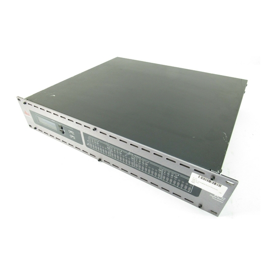
1.1 Defining the SC 32 / SC 64 The SC 32 has a maximum analog I/O count of 32 (the SC 64 has 64), configurable in banks of eight. Eight card slots facilitate five different fully loaded configurations (nine in the SC 64). -
Page 6: Service Contact Info
After expiration of the warranty, a reasonable charge will be made for parts, labor, and packing if you choose to use the factory service facility. In all cases, you are responsible for transportation charges to the factory. dbx will pay return shipping if the unit is still under warranty. -
Page 7: Warranty
In no event shall dbx or its dealers be liable for special or consequential damages or from any delay in the performance of this warranty due to causes beyond their control. -
Page 8: Section 2 - Getting Started
SC 32 / SC 64 Section 2 Getting Started Section 2 - Getting Started 2.1 Front Panel SC 32 SIGNAL SC 64 SIGNAL SIGNAL FRONT PANEL LED DISPLAY Information relating to network configuration, current time and date, HiQnet™ Node Address, SC firmware version and device status. - Page 9 SC 32 / SC 64 Section 2 Getting Started POWER LED Power present indication. CARD POSITION LABELS - I/0 CARD TYPE INDICATION LEDS Analog or digital, input or output indication per card position. Illuminate as shown below: D-IN D-OUT DESCRIPTION...
-
Page 10: Rear Panel
C 1 2 3 4 5 6 ZC INPUTS 7 - 12 OPTION SLOTS High-speed Option Slots accommodating high-bandwidth networked audio options cards (coming soon). SC 32 - One Option Slot. SC 64 - Two Option Slots. POWER CONNECTOR IEC power connector. FUSE Field-serviceable fuse. - Page 11 Balanced connections for installed I/O card. There are eight card slots in the SC 64 (slots A-H), and four card slots in the SC 32 (slots A-D). Each I/O card uses Phoenix/Combicon 3.5mm connectors to provide balanced connections. A green LED next to a connector indicates that it is an analog in connector, and an orange LED next to a connector indicates that it is an analog out connector.
-
Page 12: Section 3 - Wiring
Section 3 Wiring Section 3 - Wiring 3.1 SC 32 and SC 64 Wiring Audio Cable Wiring All audio and control connections to the SC 64/32 are via 12 terminal female Phoenix Combicon-style 3.5mm connectors, which are supplied for making these connections. - Page 13 SC 32 / SC 64 SC 32 / SC 64 Section 3 Wiring OPTO Output In addition to the six standard logic outputs, there is an isolated output, which fails safe (open circuit) if the unit becomes faulty. +supply CONTROL INPUTS...
-
Page 14: Zone Controller Wiring And Installation
SC 32 / SC 64 Section 3 Wiring 3.2 Zone Controller Wiring and Installation Zone Controller Wiring All Zone Controllers can be wired serially or in parallel. To wire in series, each Zone Controller must have an identification number (ID) chosen using the DIP switches on the side of the controller (see diagram A). - Page 15 ZC-fire interface unit monitors the state of the relay (n.o. or n.c.) and upon the state of change, notifies the SC 32/64, which then mutes its outputs. ZC-6 - The ZC-6 is a push-button up and down input or output volume controller.
- Page 16 SC 32 / SC 64 Section 3 Wiring Diagram A Diagram B ID# 1 ID# 4 80-1342-A 80-1342-A OPTION SLOT 2 ATTENTION: RISQUE DE CHOC A HARMAN INTERNATIONAL COMPANY ELECTRIQUE - NE PAS OUVRIR SALT LAKE CITY , UTAH UL60065...
- Page 17 SC 32 / SC 64 Section 3 Wiring Cable Specification: EIA/TIA 568A Standard (pin to pin) 24 AWG wire RJ-45 RJ-45 (8-Position) (8-Position) White/Green -VREF Green -Dip 1 White/Orange -Dip 2 Blue -Dip 3 White/Blue -Dip 4 Orange -Dip 5...
- Page 18 SC 32 / SC 64 Section 3 Wiring SC 32 / 64. ®...
-
Page 19: Section 4 - Technical Specifications
SC 32 / SC 64 Section 4 Technical Specifications Section 4 - Technical Specifications FRONT PANEL INDICATORS Per channel: 48V (yellow), CLIP (red), SIGNAL (green) Per 8 channel bank: IN (green), OUT (amber), D-IN (blue), D-OUT (yellow), SYNC (green) Other:... - Page 20 SC 64: 18.9 pounds (with all audio cards installed) dbx® incorporates high quality mechanical fans in some products. All mechanical fans have a limited life expectancy. We recommend annual inspection of fans for dust occlusion and excessive noise. Fan assemblies should be replaced after six to ten years of use.


Need help?
Do you have a question about the SC 32 and is the answer not in the manual?
Questions and answers