Table of Contents
Advertisement
VENT-FREE
FIREPLACE SYSTEMS
INSTALLATION AND
OPERATING INSTRUCTIONS
MODEL: 33ISDG
Natural Gas or Propane/LPG
Control Type: Milli-Volt and T-Stat
This appliance may be installed in
an aftermarket, permanently located,
manufactured (mobile) home, where
not prohibited by local codes.
This applicance is for use only with the
type of gas indicated on the rating plate.
This applicance is not convertible for
use with other gases.
This is an unvented gas-fi red heater.
It uses air (oxygen) from the room
in which it is installed. Provisions for
adequate combustion and ventilation
air must be provided. See page 9.
If the information in this manual is not followed
exactly, a fire or explosion may result causing
property damage, personal injury or loss of life.
– Do not store or use gasoline or other fl ammable
– WHAT TO DO IF YOU SMELL GAS
– Installation and service must be performed by
READ AND SAVE THESE INSTRUCTIONS
WARNINGS
WARNINGS
vapors and liquids in the vicinity of this or any
other appliance.
• Do not try to light any appliance.
• Do not touch any electrical switch; do not use
any phone in your building.
• Immediately call your gas supplier from a
neighbor's phone. Follow the gas supplier's
instructions.
• If you cannot reach your gas supplier, call the
fi re department.
a qualifi ed installer, service agency or the gas
supplier.
Advertisement
Table of Contents

Related Manuals for Martin VENT-FREE FIREPLACE SYSTEMS 33ISDG


Summary of Contents for Martin VENT-FREE FIREPLACE SYSTEMS 33ISDG
-
Page 1: Operating Instructions
VENT-FREE FIREPLACE SYSTEMS INSTALLATION AND OPERATING INSTRUCTIONS MODEL: 33ISDG Natural Gas or Propane/LPG Control Type: Milli-Volt and T-Stat This appliance may be installed in an aftermarket, permanently located, manufactured (mobile) home, where not prohibited by local codes. This applicance is for use only with the type of gas indicated on the rating plate. -
Page 2: Table Of Contents
CONTENTS Important Safety Information ...3 Product Features ...5 Operation ...5 Natural Gas ...6 Propane/LPG ...6 Specifi cations ...6 Ignition Controls ...6 Pilot ...6 Thermal Generator ...6 Getting Started ...7 General Installation Information ...8 Removing Screen ...8 Installing Canopy ...8 Codes ...9 Adequate combustion and Ventilation Air ...9 Clearances and Height Requirements ...11 Fireplace Framing...14... -
Page 3: Important Safety Information
INSTALLER Please leave these instructions with the appliance. Read these instructions carefully before installing or trying to operate this vent-free gas heater. • Any change to this heater or its controls can be dangerous. • Improper installation or use of the heater can cause serious injury or death from fi re, burns, explosion or carbon monoxide poisoning. - Page 4 IMPORTANT SAFETY INFORMATION Continued from page 3 16. Keep room area clear and free from combustible materi- als, gasoline and other flammable vapors and liquids. 17. Unvented gas heaters are a supplemental zone heater. They are not intended to be the primary heating appli- ance.
-
Page 5: Product Features
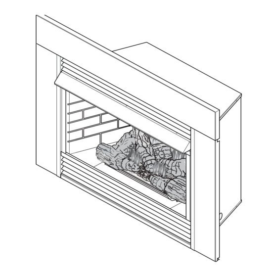
PRODUCT FEATURES Optional Face Plate Fireplace Screen Optional T-stat Sensor On/Off Switch Piezo Ignitor Blower Control Knobs Figure 1 - Unvented Gas Heater with Control Access Door Open Your vent-free fireplace must be mounted to the floor or the fireplace hearth. OPERATION This unvented gas heater requires no outside venting and burns cleanly with high heating efficiency. -
Page 6: Natural Gas
PRODUCT FEATURES NATURAL GAS Milli-Volt and T-Stat Pressure Regulator Pressure Setting: 3.5" w.c. Pilot Regulator: 3.5" w.c. Gas Inlet Pressure: Max. 10 1/2" w. c. Min. 5" w.c. Model Number 33ISDNTG 33ISDNVG PROPANE/LPG Note: An external regulator is required to reduce supply pressure to a maximum of 13" w.c. Milli-Volt and T-Stat Pressure Regulator Pressure Setting: 10"... -
Page 7: What You Will Need For Installation
MAKE SURE YOU HAVE RECEIVED ALL PARTS Check your packing list to verify that all listed parts have been received. You should have the following: • Installation/Operating instructions • 33" unvented gas heater with brick panels. • Volcanic rock and rock wool •... -
Page 8: General Installation Information
GENERAL INSTALLATION INFORMATION REMOVING SCREEN Remove fireplace screen by pushing screen frame panel up and out. See Figure 2. Do not operate the unit without the screen frame panel and canopy installed. NOTE: Fireplace screen must be removed to access log box and to install canopy. -
Page 9: Codes
CODES Adhere to all local codes or, in their absence, the latest edition of THE NATIONAL FUEL GAS CODE ANSI Z223.1 or NFPA54 which can be obtained from… Do not install the heater … • Where curtains, furniture, clothing, or other fl ammable objects are less than 42" from the front of the heater. - Page 10 GENERAL INSTALLATION INFORMATION Figure 4 - Example of a Large Room with 1/2 Wall Divider The following formula can be used to determine the maximum heater rating per the definition of unconfined space: BTU/Hr = Consider two connecting rooms with an open area between, with the following dimensions: If there were a door between the two rooms the calculation would be based only on the room with the heater.
-
Page 11: Clearances And Height Requirements
The dimensions shown in Figures 5 and 8 and defi ned in the fi replace manufacturer's instructions are minimum clearances to maintain when installing this heater. Left and right clearances are determined when facing the front of the heater. Follow these instructions carefully to ensure safe installation. Failure to follow instructions exactly can create a fi... - Page 12 CLEARANCES and HEIGHT REQUIREMENTS No combustible materials within 8” of opening. Do not cover louvers. Figure 7 - Measuring Heat Resistant Material for Mantel " No combustible materials within 8" of opening. Do not cover louvers. Figure 9 - Unsafe Mantel Clearance HEAT RESISTANT MATERIAL (MINIMUM REQUIRE- MENTS) WITH NO WOODEN MANTEL OR OTHER COM- BUSTIBLE PROJECTION...
- Page 13 The gas log heater must be installed at least 5" above any combustible flooring material, such as carpeting or tile, which is closer than 14" to the base of the fireplace. See Figure 10. Non-combustible Material Figure 10 - Minimum Clearance above Combustible Flooring 23D8036 CLEARANCES and HEIGHT REQUIREMENTS Combustible...
-
Page 14: Fireplace Framing
FIREPLACE FRAMING If unit is to be “built in,” fireplace framing can be built before or after the appliance is set in place. BE SURE THAT ALL PACKING MATERIAL HAS BEEN REMOVED FROM THE UNDERSIDE OF THE UNIT PRIOR TO SETTING THE FIREBOX IN PLACE. -
Page 15: Securing Heater To Floor
NOTE: Clearance requirements as detailed in “Clearances and Height Requirements” section of this manual must be met before securing heater in place. To prevent movement, the heater must be secured to the floor or hearth. 1. Lift off louvers and remove the screen. 2. -
Page 16: Connecting The Gas
CONNECTING THE GAS NOTICE: A qualifi ed gas appliance installer must connect the heater to the gas supply. Consult all local codes. Use new black or steel pipe. Internally tinned copper or copper tubing can be used per National Fuel Code, section 2.6.3, providing gas meets hydrogen sulfi de limits, and where permitted by local codes. - Page 17 CHECK GAS TYPE: The gas supply must be the same as stated on heater's rating plate. Located behind the control access door (Figure 1, page 5). If the gas supply is different, DO NOT INSTALL the heater. Contact your dealer for the correct model. Connecting to the wrong gas type may result in property damage or personal injury.
-
Page 18: Checking Gas Pressure
CHECKING GAS PRESSURE Connecting directly to an unregulated propane/LPG tank can cause an explosion. Test all gas joints from the gas meter to the heater valve for leaks using a gas analyzer or soap and water solution after com- pleting connection. DO NOT USE AN OPEN FLAME. Check the gas pressure with the appliance burning and the control set to HIGH. -
Page 19: Connecting Optional Wall Switch Or Thermostat
The milli-volt valve is a self-powered combination gas control THAT DOES NOT REQUIRE 110 VAC TO OPERATE. Wall Switch On/Off Switch TH = 3 TP = 1 TP/TH = 2 See Figure 20 and installation instructions provided with optional wall switch, thermo- stat or remote control for wiring instructions. -
Page 20: Checking System Operation
ELECTRICAL WIRING (MILLI-VOLT) CONNECTING REMOTE RECEIVER (Figure 21) THESE INSTRUCTIONS SUPERCEDE THE SECTION ENTITLED “HEARTH MOUNT” IN THE MILLI-VOLT HAND-HELD REMOTE INSTRUCTIONS SUPPLIED WITH THE REMOTE. 1. Remove cover on control panel to show opening for remote receiver. 2. Connect the remote connectors located in the unit. 3. -
Page 21: Electrical Wiring (Fan)
This fi replace has a three-prong, grounded electrical plug. This plug helps protect you against electrical shock. Only connect plug to a properly grounded, three-prong receptacle. Do not cut or remove the grounded prong from this plug. IMPORTANT: Always check local building codes. The installation must comply with local regulations as well as the national electric codes. -
Page 22: Log Placement
LOG PLACEMENT Before you begin — This unit is supplied with six (6) ceramic fi ber logs. Do not handle these logs with your bare hands. Always wear gloves to prevent skin irritation from ceramic fi bers. After handling the logs, wash your hands gently with soap and water to remove any traces of fi... - Page 23 3. Place left base log (#3) on two pins on left side of grate. See Figure 21. Pins 4. Place right top log (#4) on two pins located to the left of right base log. See Figure 22. Right Top Log (#4) Pins 23D8036...
- Page 24 LOG PLACEMENT 5. Place right end of left top log (#5) on bottom center grate pin. Rest the left end of left top log (#5) on the left base log. See Figure 23. Left Top Log (#5) Left Base Log (#3) Bottom Center Pin Figure 23 - Installing Left Top Log (#5) 23D8036...
- Page 25 6. Place right front log (#6) on two pins on the right front of grate. See Figure 25. Pins PLACING ROCK WOOL After installing logs, place TPB-RW (Rock Wool) in dime-size pieces evenly across the burner surface in between the logs. Do not add additional Rock Wool.
-
Page 26: Flame Appearance
FLAME APPEARANCE Flames from the pilot, front and rear burner should be visually checked as soon as the heater is installed. In addition, periodically check the flames visually during operation. CHECKING THE PILOT FLAME The pilot fl ame must always be present when the heater is in operation. It should just touch the top of the ther- mocouple tip for natural. -
Page 27: Checking The Burner Flame
CHECKING THE BURNER FLAME In normal operation at full rate after 15 minutes, the following flame appearances should be observed: Glowing Embers Figure 33 - Correct Appearance of Rear Flames Burner will have a random pattern of yellow flames as shown in Figure 33. There should be glowing embers on the front burner. -
Page 28: Operating Instructions
OPERATING INSTRUCTIONS FOR YOUR SAFETY READ BEFORE LIGHTING A. This appliance is equipped with a piezo ignition device which automatically lights the pilot. If pilot is not working see Match Lighting Instructions on page 30. B. BEFORE OPERATING smell all around the appliance area for gas. Be sure to smell next to the floor because some gas is heavier than air and will settle on the floor. -
Page 29: To Turn Off Gas To Heater
MILLI-VOLT/THERMOSTAT CONTROL 1. STOP! Read the safety information label. 2. Make sure the manual shutoff valve is fully open. 3. This gas log set is equipped with an ignition device (piezo) which automatically lights the pilot. If piezo ignitor does not light the pilot, refer to instructions for “Match Lighting Instructions,” page 30. 4. -
Page 30: Match Lighting Instructions
OPERATING INSTRUCTIONS MATCH LIGHTING INSTRUCTIONS 1. Remove any items necessary for easy access to the pilot (for example: logs, screens, etc.). 2. Follow appropriate lighting instructions found previously. Instead of pushing and releasing the piezo button, light a match and hold the flame to the end of the pilot and ignite the pilot. 3. -
Page 31: Cleaning And Servicing
Annual inspection and cleaning by your dealer or qualified service technician is recommended to prevent malfunction and/or sooting. Remove logs, handling carefully by holding gently at each end. Gloves are recommended to prevent skin irritation from ceramic fibers. If skin becomes irritated, wash gently with soap and water. Refer to manual for correct log placement. PERIODIC CLEANING - Refer to parts diagram for location of items discussed below. -
Page 32: Troubleshooting
TROUBLESHOOTING Note: All troubleshooting items are listed in order of operation. OBSERVED PROBLEM When ignitor button is pressed, there is no spark at ODS/pilot. Appliance produces unwanted odors. Appliance shuts off during use. Gas odor even when control knob is in OFF position. When ignitor button is pressed, there is spark at ODS pilot, but no ignition. - Page 33 If the gas quality is bad, your pilot may not stay lit, the burners may produce soot and the heater may backfi re when lit. If the gas quality or pressure is low, contact your local gas supplier immediately. OBSERVED PROBLEM ODS/pilot lights, but flame goes out when control knob is released.
-
Page 34: Illustrated Parts Breakdown
ILLUSTRATED PARTS BREAKDOWN Failure to position the parts in accordance with these diagrams or failure to use only parts specifi cally approved with this appliance may result in property damage or personal injury. 23D8036... -
Page 35: Replacement Parts List
Item OPTIONAL FACE PLATE OPTIONAL BLOWER COMPONENTS 23D8036 Description Screen Assembly Canopy Assembly Top Black Louver Bottom Black Hang On Louver Assembly Left Firebrick Right Firebrick Center Firebrick 33" x 43" Black Face Plate Kit 36" x 50" Black Face Plate Kit Fan Blower with Speed Control Blower Thermostat Wiring Harness... -
Page 36: Grate And Base Assembly
ILLUSTRATED PARTS BREAKDOWN Failure to position the parts in accordance with these diagrams or failure to use only parts specifi cally approved with this appliance may result in property damage or personal injury. 23D8036... - Page 37 REPLACEMENT PARTS ARE AVAILABLE THROUGH YOUR RETAILER. Item Common Parts Milli-Volt Control Accessories 23D8036 Description 33ISDN Piezo Ignitor 14D0503 Piezo Wire 00K0632 Burner 70D0104 Control Valve 14D0467 Burner Injector 58D0051 ODS Pilot Assembly 14D0473 Pilot/On/Off Knob Extension 37D0010 Hi/Lo Knob 37D0011 On/Off Switch 32D0232...
-
Page 38: Logs
ILLUSTRATED PARTS BREAKDOWN REPLACEMENT PARTS ARE AVAILABLE THROUGH YOUR RETAILER. BLAZING OAK LOGS Failure to position the parts in accordance with these diagrams or failure to use only parts specifi cally approved with this appliance may result in property damage or personal injury. - Page 39 NOTES 23D8036...
-
Page 40: Limited Lifetime Warranty Policy
LIMITED LIFETIME WARRANTY POLICY The following components are warranted for life to the original owner, subject of proof of purchase: Firebox, Combustion Chamber, Heat Exchanger, Grate, and Stainless Steel Burners. FIVE YEAR WARRANTY The following components are warranted for 5 years to the original owner, subject of proof of purchase: Vent Free Ceramic Fiber Logs, Catalytic Filter and Aluminized Burners.
Need help?
Do you have a question about the VENT-FREE FIREPLACE SYSTEMS 33ISDG and is the answer not in the manual?
Questions and answers