Miele KM 6112 Operating And Installation Instructions
Hide thumbs
Also See for KM 6112:
- Operating and installation instructions (72 pages) ,
- Operating and installation manual (68 pages) ,
- Operating and installation instructions (72 pages)
Table of Contents

Related Manuals for Miele KM 6112


Summary of Contents for Miele KM 6112
- Page 1 Operating and installation instructions Ceramic hobs with induction To avoid the risk of accidents or damage to the appliance it is essential to read these instructions before it is installed and used for the first time. en-GB M.-Nr. 07 798 970...
-
Page 2: Table Of Contents
Caring for the environment ................. 13 Overview ....................... 14 Hob ........................14 KM 6113 ......................14 KM 6112 / KM 6115 / KM 6116 ................ 15 KM 6117 ......................16 KM 6118 ......................17 Controls / Indicators ....................18 Cooking zones ....................... 20 Using for the first time.................. - Page 3 Problem solving guide ..................46 Optional accessories ................... 50 Safety instructions for installation ..............51 Safety distances....................52 Installation notes....................56 Building-in dimensions ..................57 KM 6112......................... 57 KM 6113......................... 58 KM 6115......................... 59 KM 6116......................... 60 KM 6117......................... 61 KM 6118......................... 62 Installation ......................
-
Page 4: Warning And Safety Instructions
They contain important notes on in‐ stallation, safety, use and maintenance. Miele cannot be held liable for damage caused by non-compli‐ ance with these instructions. Keep these instructions in a safe place and ensure that new users... - Page 5 Warning and Safety instructions Correct application This hob is intended for domestic use and use in other similar en‐ vironments. This hob is not intended for outdoor use. It is intended for domestic use only to cook food and keep it warm.
- Page 6 Warning and Safety instructions Safety with children Children under 8 years of age must be kept away from the hob unless they are constantly supervised. Children 8 years and older may only use the hob unsupervised if they have been shown how to use it in a safe way and can recognise and understand the consequences of incorrect operation.
- Page 7 Unauthorised installation, maintenance and repairs can cause considerable danger for the user. Installation, maintenance and re‐ pairs must only be carried out by a Miele authorised technician. Do not use a damaged appliance. It could be dangerous. Check the hob for visible signs of damage.
- Page 8 Warning and Safety instructions Miele can only guarantee the safety of the appliance when genu‐ ine original Miele replacement parts are used. Faulty components must only be replaced by Miele spare parts. The hob is not intended for use with an external timer switch or a remote control system.
- Page 9 Warning and Safety instructions Correct use The hob gets hot when in use and remains hot for a while after being switched off. There is a danger of burning until the residual heat indicators go out. Due to the high temperatures radiated, objects left near the hob when it is in use could catch fire.
- Page 10 Warning and Safety instructions You could burn yourself on the hot hob. Protect your hands with heat-resistant pot holders or gloves when handling hot pots and pans. Do not let them get wet or damp, as this causes heat to trans‐ fer through the material more quickly with the risk of scalding or burning yourself.
- Page 11 Warning and Safety instructions Induction heating works extremely quickly and so the base of the pan could heat up to the temperature at which oil or fat self-ignites within a very short time. Do not leave the hob unattended whilst it is being used.
- Page 12 Warning and Safety instructions Cleaning and care Do not use a steam cleaning appliance to clean this hob. The steam could reach electrical components and cause a short cir‐ cuit. If the hob is built in over a pyrolitic oven, the hob should not be used whilst the pyrolitic process is being carried out, as this could trigger the overheating protection mechanism on the hob (see rele‐...
-
Page 13: Caring For The Environment
Caring for the environment Disposal of the packing mate‐ Disposal of your old appliance rial Electrical and electronic appliances of‐ ten contain valuable materials. They al‐ The packaging is designed to protect so contain materials which, if handled the appliance from damage during or disposed of incorrectly, could be po‐... -
Page 14: Overview
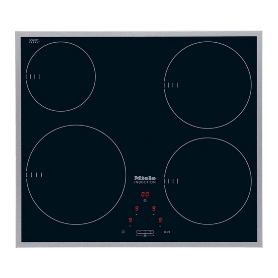
Overview KM 6113 a Cooking zone with TwinBooster b Cooking zone with Booster c Cooking zone with Booster d Controls / Indicators... - Page 15 Overview KM 6112 / KM 6115 / KM 6116 a Cooking zone with TwinBooster b Cooking zone with Booster c Cooking zone with Booster d Cooking zone with Booster e Controls / Indicators...
- Page 16 Overview KM 6117 a Cooking zone with TwinBooster b Cooking zone with Booster c Cooking zone with TwinBooster d Cooking zone with Booster e Controls / Indicators...
- Page 17 Overview KM 6118 a Cooking zone with TwinBooster b Cooking zone with Booster c Cooking zone with Booster d Cooking zone with Booster e Controls / Indicators...
-
Page 18: Controls / Indicators
Overview Controls / Indicators Sensor controls a For switching the hob on and off b Setting - For setting the power level - For setting the timer - For activating/deactivating the system lock/safety lock c For switching the Booster / TwinBooster On/Off d For selecting the cooking zone e Timer - For switching on/off... - Page 19 Overview j Shows cooking zone selection, e.g. rear right cooking zone k Minute minder l In half hours if the minute minder setting exceeds 99 minutes g Cooking zone display Cooking zone ready for use Keeping warm setting ...
-
Page 20: Cooking Zones
* Pans with a base diameter within the given range may be used. ** The wattage quoted may vary depending on the size and material of the pans used. Cooking zone KM 6112 / KM 6115 / KM 6116 / KM 6118 Ø in cm* Rating in watts for 230 V** 16–23... - Page 21 Overview Cooking zone KM 6117 Ø in cm* Rating in watts for 230 V** 16–23 Normal 2300 TwinBooster, level 1 3000 TwinBooster, level 2 3700 10–16 Normal 1400 Booster 2200 14–20 Normal 1850 TwinBooster, level 1 2500 TwinBooster, level 2 3000 20 x 30...
-
Page 22: Using For The First Time
Using for the first time Please stick the extra data plate for Switching on the hob for the the appliance supplied with this doc‐ first time umentation in the space provided in The metal components have a protec‐ the "After sales service, data plate, tive coating which may give off a slight guarantee"... -
Page 23: Induction
Induction The induction principle When the appliance is switched on either deliberately or by mistake, An induction coil is located under each or when there is residual heat cooking zone. When a cooking zone is present, there is the risk of any metal switched on, this coil creates a magnet‐... -
Page 24: Noises
Induction Noises When using an induction cooking zone, the following noises can occur in the pan, depending on what it is made of and how it has been constructed. On the higher power settings, it might buzz. This will decrease or cease alto‐ gether when the power setting is re‐... -
Page 25: Pans
Induction Pans – Often the maximum diameter quoted by manufacturers refers to the diam‐ The following pan types are suitable: eter of the top rim of the pot or pan. The diameter of the base (generally – Stainless steel with a base that can smaller) is more important. -
Page 26: Tips On Saving Energy
Tips on saving energy – Use a lid whenever possible to mini‐ mise heat loss. – Select a smaller pan when cooking small quantities. A smaller pan uses less energy than a larger pan with very little in it. – Cook with as little water as possible. –... -
Page 27: Setting Range
Setting range The hob is programmed with 9 power levels at the factory. If you wish to fine-tune a setting, you can extend the power setting range to 17 power levels (see "Pro‐ gramming"). Setting range Default set‐ Extended set‐ ting tings (9 power lev‐... -
Page 28: Operation
Operation Operation Malfunction due to dirty and/or cov‐ ered sensors This glass ceramic hob is equipped If the sensors are dirty or covered with electronic sensor controls which this could cause them to fail to react, react to finger contact. For safety rea‐ to activate a function or even to sons, in order to switch the hob on, the switch the hob off automatically (see... -
Page 29: Switching On
Operation To switch off the hob and all the Fire hazard. cooking zones, touch the sensor. Do not leave the hob unattended whilst it is being used. Residual heat indicator Please note that the heating up time If the cooking zone is still hot, the resid‐... -
Page 30: Auto Heat-Up
Operation Auto heat-up Continued cook‐ Heat-up time ing setting [min : sec] When Auto heat-up has been activated, the cooking zone switches on automati‐ approx. 0 : 15 cally at the highest power setting and approx. 0 : 15 then switches to the continued cooking setting. -
Page 31: Booster
Operation Booster Cooking zones are networked in pairs to supply the power for the booster The cooking zones are equipped with a function. When the booster function is Booster or TwinBooster (see "Guide to selected, a proportion of energy is tak‐ the appliance –... - Page 32 Operation To switch on the Booster Touch the B I/II sensor repeatedly until the indicator lamp for the Boos‐ Touch the sensor for selecting the ter goes out and the cooking zone cooking zone you want. setting shows in the display. ...
-
Page 33: Keeping Warm
Operation Keeping warm Setting the keeping warm function Touch the sensor for selecting the The keeping warm function is for cooking zone you want. keeping food that has just been Touch the + sensor until appears in cooked warm, i.e. -
Page 34: Timer
Timer Minute minder The hob has to be switched on if you wish to use the timer. Setting You can set a time between 1 minute () and 9.5 hours (.). Touch the sensor. and the minute minder indicator The timer can be used for two different lamp will flash in the timer display. -
Page 35: Switching A Cooking Zone Off Automatically
Timer Switching a cooking zone off If you want to set another cooking zone to switch off automatically, fol‐ automatically low the same steps as described You can set a time at the end of which above. a cooking zone will switch off automati‐ cally. -
Page 36: Using Both Timer Functions At The Same Time
Timer Using both timer functions at If you want to show the times counting down in the background: the same time Touch the timer display repeately un‐ The minute minder and automatic switch-off functions can be used at the same time. -
Page 37: Safety Features
Safety features System lock / Safety lock The safety lock is set when the hob is switched on. When the safety lock is The system lock and safety lock are activated, deactivated if there is an interruption – the cooking zone power levels and to the power supply. -
Page 38: Power Management
Safety features Power management Safety switch-off The total output of the hob can be limi‐ Safety switch-off with an overlong ted to 3.0 kW in order to match to the cooking time requirements of a local network provid‐ The safety switch-off mechanism is er. -
Page 39: Overheating Protection
If, despite removing the cause, the – The set power level will be reduced. overheating protection mechanism trig‐ gers again, contact Miele Service. – The cooking zone will switch off au‐ tomatically. The fault code will Control panel appear. -
Page 40: Cleaning And Care
Cleaning and care Clean the entire hob after each use. Al‐ Danger of burning. low it to cool down before cleaning. Dry The cooking zones must be switch‐ the hob after using water to clean it. ed off. The hob must have cooled This helps prevents limescale deposits. - Page 41 Wipe all coarse soiling off using a damp cloth. Stubborn soiling may need to be removed with a shielded scraper blade. Then clean the hob with Miele ceramic and stainless steel hob cleaner (see "Optional accessories") or a suitable proprietary ceramic hob cleaner applied with kitchen paper or a clean cloth.
-
Page 42: Programming
Programming You can programme certain settings on To access programming mode the hob to suit your personal needs. With the hob switched off touch Several settings can be changed in the and B I/II sensors at the same succession. - Page 43 Programming Settings Programme Status Demonstration Demonstration mode on mode and factory Demonstration mode off default settings Factory default settings reinstated Number of power 9 power levels levels 17 power levels Induction warning tone when there is Quiet no pan in place or the pan is unsuita‐...
- Page 44 Programming Settings Programme Status Power manage‐ ment Buzzer tone if the sensors are cov‐ ered Sensor reaction Slow speed Normal Rapid Unlisted programmes are not assigned. The factory setting is shown in bold. After the hob has been switched on, will appear in the front left cooking zone display and ...
-
Page 45: Reset
Programming Reset This function allows you to quickly reset all the programming settings back to their original factory default settings. To initiate reset Switch on the hob. Touch the sensors for selecting the front left and front right cooking zones at the same time until the cooking zone displays go out (ap‐... -
Page 46: Problem Solving Guide
Do not open the casing of the appliance. Repairs and other work by unqualified persons could be dangerous and Miele cannot be held liable for unauthorised work. Problem... - Page 47 Problem solving guide Problem Cause and remedy After switching on the The system lock or safety lock is activated. hob, appears in the Deactivate the system lock or safety lock (see front left cooking zone "System lock / Safety lock"). display and ...
- Page 48 Interrupt the power supply to the hob for approx. 1 minute. If the problem persists after power has been re‐ stored, please contact Miele. The hob does not One or more of the sensors are covered, e.g. by fin‐...
- Page 49 Make sure it has not been blocked by something like a fork. Remove the cause of the blockage. If this fault code continues to appear in the dis‐ play, contact Miele Service. and other numbers There is a fault in the electronic module.
-
Page 50: Optional Accessories
250 ml Miele appliances. These can be ordered online at: Removes heavy soiling, limescale de‐ posits and aluminium residues or from Miele (see end of this booklet Microfibre cloth for contact details). Pans Miele offer a wide range of pans which are perfect for Miele hobs. -
Page 51: Safety Instructions For Installation
Safety instructions for installation The appliance must only be installed and connected to the electricity sup‐ ply by a suitably qualified and competent person in strict accordance with cur‐ rent national and local safety regulations. Fit the wall units and cooker hood before fitting the hob to avoid damaging the hob. -
Page 52: Safety Distances
Safety distances Safety distance above the hob A minimum safety distance must be maintained between the appliance and the cooker hood above it. See the cooker hood manufacturer's operating and installation instructions for details. If the manufacturer's instructions are not available for the cooker hood, a minimum safety distance of at least 760 mm must be maintained. - Page 53 Safety distances Safety distances to the sides and back of the hob Ideally the hob should be installed with plenty of space on either side. There may be a wall at the rear or a tall unit or wall on one side (right or left) (see illus‐ trations).
- Page 54 Safety distances Minimum safety distances un‐ Interim shelf derneath the hob It is not necessary to fit an interim shelf underneath the hob but one may be fit‐ To ensure sufficient ventilation to the ted if you wish. hob, a certain gap must be left between the underside of the hob and any oven, Leave a gap of 10 mm at the back of interim shelf or drawer.
- Page 55 Safety distances Safety distance when installing the appliance near a wall with additional niche cladding A minimum safety distance must be maintained between the worktop cut-out and any niche cladding to protect it from heat damage. If the niche cladding is made from a combustible material (e.g. wood) a minimum safety distance ...
-
Page 56: Installation Notes
Installation notes Seal between the hob and the Tiled worktop worktop Grout lines and the hatched area un‐ derneath the hob frame must be smooth and even. If they are not the Do not use sealant between the hob hob will not sit flush with the worktop and the worktop. -
Page 57: Building-In Dimensions
Building-in dimensions KM 6112 a Front b Casing depth c Mains connection box The mains connection cable (1440 mm long) is supplied separately with the hob. - Page 58 Building-in dimensions KM 6113 a Front b Casing depth c Mains connection box The mains connection cable (1440 mm long) is supplied separately with the hob.
- Page 59 Building-in dimensions KM 6115 a Front b Casing depth c Mains connection box The mains connection cable (1440 mm long) is supplied separately with the hob.
- Page 60 Building-in dimensions KM 6116 a Front b Casing depth c Mains connection box The mains connection cable (1440 mm long) is supplied separately with the hob.
- Page 61 Building-in dimensions KM 6117 a Front b Casing depth c Mains connection box The mains connection cable (1440 mm long) is supplied separately with the hob.
- Page 62 Building-in dimensions KM 6118 a Front b Casing depth c Mains connection box The mains connection cable (1440 mm long) is supplied separately with the hob.
-
Page 63: Installation
Installation Preparing the worktop Installing the hob Make the worktop cut-out as shown Feed the mains connection cable in the building-in diagram. Observe down through the cut-out. the safety distances (see "Safety dis‐ Place the hob centrally in the cut-out. tances"). -
Page 64: Electrical Connection
Electrical connection Connection Danger of injury. Miele cannot be held liable for unau‐ AC 230 V, 50 Hz thorised installation, maintenance The connection data is quoted on the and repair work as this can be dan‐ dataplate. It must match the household gerous to users. - Page 65 . If the mains cable needs to be replaced it must be replaced with a special con‐ nection cable, type H 05 VV-F (PVC-in‐ sulated), available from Miele. The connection data is quoted on the data plate.
-
Page 66: Wiring Diagram
Electrical connection Wiring diagram a b c d e 200-240 V~ 200-240 V~ 200-240 V~ (L3) 200-240 V~ 200-240 V~ b c d (L2) 200-240 V~... -
Page 67: After Sales Service, Data Plate
– your Miele Dealer, or – Miele Service. See end of this booklet for contact details. When contacting your Dealer or Miele, please quote the model and serial number of your appliance. Data plate Space in which to stick the extra data plate supplied with the appliance. Ensure that the model number is the same as the one on the back page of these instruc‐... -
Page 68: Product Data Sheets
Information about domestic electric hobs In acc. with regulation (EU) No. 66/2014 MIELE Model name / identifier KM 6112 Number of cooking zones and/or areas For circular cooking zones: diameter of useful sur‐ 1. = Ø 160-230 mm face area/cooking zone 2. - Page 69 Product data sheets Information about domestic electric hobs In acc. with regulation (EU) No. 66/2014 MIELE Model name / identifier KM 6115 Number of cooking zones and/or areas For circular cooking zones: diameter of useful sur‐ 1. = Ø 160-230 mm face area/cooking zone 2.
- Page 70 Product data sheets Information about domestic electric hobs In acc. with regulation (EU) No. 66/2014 MIELE Model name / identifier KM 6117 Number of cooking zones and/or areas For circular cooking zones: diameter of useful sur‐ 1. = Ø 160-230 mm face area/cooking zone 2.
- Page 71 Citywest Business Campus, Dublin 24 Dubai Tel: (01) 461 07 10, Fax: (01) 461 07 97 Tel: +971-4-341 84 44 E-Mail: info@miele.ie, Internet: www.miele.ie Fax: +971-4-341 88 52 Manufacturer: Miele & Cie. KG E-Mail: info@miele.ae Internet: www.miele.ae Carl-Miele-Straße 29, 33332 Gütersloh, Germany...
- Page 72 KM 6112 / KM 6113 / KM 6115 / KM 6116 / KM 6117 / KM 6118 en-GB M.-Nr. 07 798 970 / 07...
Need help?
Do you have a question about the KM 6112 and is the answer not in the manual?
Questions and answers