Table of Contents
Advertisement
Advertisement
Table of Contents

Related Manuals for KYORITSU KEW 4106


Summary of Contents for KYORITSU KEW 4106
- Page 1 Instruction Manual Earth Resistance/ Earth Resistivity Tester KEW 4106...
-
Page 3: Table Of Contents
Contents 1. Safety Warnings ....................1 2. How to store the Cover ..................5 2-1 Method of removing the Cover ...............5 2-2 Method of storing the Cover ..............5 3. Features ......................6 4. Specifications ....................7 5. Instrument Layout ..................10 6. Marks and messages on the LCD .............. 13 7. - Page 4 9. Measurement Method ................... 24 9-1 Earth Resistance Measurement ............24 9-1-1 Precise Measurement (3-Wire) ............. 25 9-1-2 Precise Measurement (4-Wire) ............. 27 9-1-3 Simplified Measurement (2-Wire) ..........29 9-2 Earth Resistivity (ρ) Measurement ............ 31 10. Save/ Recall the Measurement Results ............ 34 10-1 How to save the data .................
-
Page 5: Safety Warnings
1. Safety Warnings This instrument has been designed, manufactured and tested according to IEC 61010: Safety requirements for Electronic Measuring apparatus, and delivered in the best condition after passing quality control tests. This instruction manual contains warnings and safety rules which have to be observed by the user to ensure safe operation of the instrument and to maintain it in safe condition. - Page 6 # DANGER ● Never make measurement on a circuit in which electrical potentials exceeding AC/DC300V exist. ● Do not attempt to make measurement in the presence of flammable gasses. Otherwise, the use of the instrument may cause sparking, which can lead to an explosion. ●...
- Page 7 # CAUTION ● Set and check the Range switch to the appropriate position before making measurement. ● Set the Range switch to “OFF” position after use and remove the test leads. The instrument consume small current at any range other than OFF, and it shortens the battery life.
- Page 8 Symbols The circuit from the service drop to the service entrance, and CAT.IV to the power meter and primary overcurrent protection device (distribution panel) Primary electrical circuits of the equipment connected directly to CAT.III the distribution panel, and feeders from the distribution panel to outlets.
-
Page 9: How To Store The Cover
2. How to store the Cover This instrument has a dedicated Cover to protect against impacts from the outside and prevent the instrument body from becoming dirty. The Cover can be detached and put on the backside of the main body during measurements. -
Page 10: Features
3. Features KEW4106 is a 2/ 3/ 4-Wire Digital Earth Resistance/ Earth Resistivity Tester equipped with a microcomputer and can measure earth resistances and calculate earth resistivities (ρ). This instrument can measure earth resistances on power distribution lines, in-house wiring system and electrical appliances etc. -
Page 11: Specifications
4. Specification ● Applicable Standards IEC 61010-1 Measurement CAT.III 300V, CAT.IV 150V Pollution degree 2 IEC61010-2-030 Measurement CAT.III 300V, CAT. IV 150V Pollution degree 2 IEC 61010-031 Standard for hand-held Probes IEC 61557-1, 5 Earth Resistance Tester ... - Page 12 ● Measuring method for Earth Resistance Fall-of-potential method (currents and voltages measured via the Probes) ● Measurement method of Earth Resistivity (ρ) Wenner 4-pole method ● Output Characteristics Measuring Voltage Um (max.) approx 10Vrms 94Hz, 105Hz, 111Hz, 128Hz Measuring Current Im (max.) approx 80mA, however, Im ×(Re+Rh)...
- Page 13 ● Dimension 167(L) x 185(W) x 89(D)mm ● Weight approx 900g (including batteries) ● Power source DC12V : sizeAA manganese dry battery (R6P) x 8 pcs * In a use of this instrument under low temperature below 0ºC, a use of alkaline batteries with low temperature spec is recommended.
-
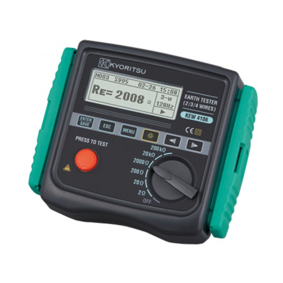
Page 14: Instrument Layout
5. Instrument Layout ● Instrument body and Connector ⑤ ⑥ ① ② ③ ④ ⑧ ⑦ ⑨ ⑩ ⑪ ⑫ ⑬ ① ② ENTER/SAVE Key ③ ESC Key ④ MENU Key ⑤ Backlight Key ⑥ Cursor Key ⑦ TEST Button ⑧... - Page 15 ● LCD Indications Site No. Time Month-Day Memory No. Wiring Measuring signal frequency Main Display Cursor Key is active. Result Display Screen ● Accessories # DANGER ● Do not connect the Precision Measurement Test Leads where electrical potentials exceeding 33Vrms with peak value of 46V or DC70V. ...
- Page 16 Auxiliary Earth Spike MODEL8032 x 2 sets (4 spikes in total) Cord Reel MODEL8200-04 x 1set (4reels in total) (for MODEL7229A) Optical Adaptor MODEL8212USB x 1 set Communication Software CD-ROM “KEW Report” x 1 pce SizeAA Manganese battery (R6P) x 8 pcs Carrying case MODEL9125 Shoulder strap x 1 pce...
-
Page 17: Marks And Messages On The Lcd
6. Marks and Messages displayed on the LCD Following marks and messages are displayed while measurements. Marks and Messages Details Battery voltage is low. Replace the batteries. This mark is being displayed during a measurement. Measuring range for the selected Range is exceeded. -
Page 18: Measurement Principle
7. Measurement Principle 7-1 Principle of Earth Resistance Measurements This instrument makes earth resistance measurements with fall-of-potential method, which is a method to obtain earth resistance value “Rx” by applying AC current “I” between the measurement object “E” (earth electrode) and “H(C)”... -
Page 19: Preparation For Measurement
8. Preparation for Measurement 8-1 Battery Voltage Check Power on the instrument. If the display is clear without the Low battery mark " " showing, battery voltage is sufficient. If the display blanks or the Low battery mark is indicated (Fig.5), replace the batteries according to “11. for Battery and Fuse Replacement”... -
Page 20: Setting For Measurement Method
Settings of following parameters can be made on this instrument ● Wire : Measurement method (Wiring System) ● Freq : Measurement frequency ● Site : Site (location) No ● Lh : Interval of the auxiliary earth spikes at Earth resistivity (ρ) measurement ●... -
Page 21: Site (Location) No. Setting
Selecting a desirable frequency with the Cursor Key, and pressing the “ “ Key returns to the “CONFIG_SETTING” Screen (Fig.12) with the selected frequency. Fig. 12 8-2-4 Site (location) No. Setting The site (location) where measurements done can be saved with numbers. Select “Site”... -
Page 22: Setting For The Interval Between Auxiliary Earth Spikes
8-2-5 Setting for the interval between Auxiliary Earth Spikes at Earth Resistivity (ρ) Measurements Making setting of the intervals between auxiliary earth spikes is necessary to measure earth resistivity (ρ). Select “Lh” with the Cursor Key on the CONFIG_SETTING Screen, and press the “... - Page 23 Time Setting can be done in following procedure. Select “Date/Time” with the Cursor Key on the CONFIG_SETTING Screen, and press the “ ” Key to display the Time and Date Setting Screen (Fig.19). Fig. 19 (1) Time Setting Put the cursor on “Time” and press the “ ”...
- Page 24 (2) Date Setting Date is displayed in the following order: Month/ Day/ Year. Put the cursor on “Date” and press the “ ” Key to display the Date Setting Screen (Fig.23). Fig. 23 Select a parameter to be changed with the Cursor Key, and press the “...
-
Page 25: Setting For The Residual Resistance (Rk) On The Test Leads
8-2-7 Setting for the residual resistance (Rk) on the Test Leads This instrument can store the residual resistance (Rk) of the Test Leads before starting Re measurements on 2/ 3/ 4-wire system, and can deduct the resistance from the measured result. The setting of Rk can be done in following procedure. -
Page 26: Backlight
Fig. 30 Following message appears and shows that the data cannot be saved when the “ ” Key is pressed with above display. Fig. 31 Note) Following message appears and shows that the data cannot be saved when trying to save Rk at 200kΩ or upper Ranges. The Rk values saved at 2Ω... -
Page 27: Series Interference Voltage (Earth Voltage) Measurement
8-5 Series Interference Voltage (Earth Voltage) Measurement Measurements are automatically started during a measurement of earth resistances and earth resistivities, and the results can be checked on the Result display screen. Warning message “Voltage High!” is displayed on the Main display when the earth voltage (Ust) is high. -
Page 28: Measurement Method
9. Measurement Method # DANGER ● No voltage should be applied between the measuring terminals at earth resistance measurements. 9-1 Earth Resistance Measurement # CAUTION ● The measured results may be influenced by induction if measure-ments are made with the Test Leads twisted or in touch with each other. When connecting the Probes, they should be separated. -
Page 29: Precise Measurement (3-Wire)
9-1-1 Precise Measurement (3-Wire) * with Earth Test Leads MODEL 7229A This is a standard method to measure earth resistances. The measured earth resistances are free of auxiliary earth resistances but the resistances on the E terminal are contained. Terminals to be used : E, S(P), H(C) Terminals Test Leads : connect to the E, S(P), H(C) Terminals... - Page 30 (4) Earth Resistance Measurement Select a Range (any Range is ok) when the connection is done, and press the TEST Button. A message “ “ is displayed at the upper right on the LCD. The measured earth resistances “Re” are displayed on the LCD when a measurement is finished.
-
Page 31: Precise Measurement (4-Wire)
# DANGER The Re measurement cannot be made when a warning message “Voltage High!!” like shown in Fig.37 appear on the LCD. Voltages more than 15V exist between the “E” and “S(P)” terminals. Fig. 37 Pressing the “ ” Key shifts the display as shown in Fig.38. Fig. - Page 32 (2) Setting of Rk The measured results obtained at 4-Wire system are not be influenced by the Test Leads Connected to the “E” Terminal, but setting of Rk can be made on this instrument. 1. Firmly insert each plug of 4 Test Leads (green, black, yellow, red), to the corresponding connectors on the instrument.
-
Page 33: Simplified Measurement (2-Wire)
Note) If a message “ ” or “ ” appear on the LCD, auxiliary earth resistance is too high to make measurements. Recheck the connection of Test Leads. 9-1-3 Simplified Measurement (2-Wire) *with Simplified Test Probes MODEL 7238A # DANGER ●... - Page 34 (1) Setting of Wiring System Select “Wire (2)” with reference to “8-2-2 Setting for Measurement Method” in this manual. (2) Setting of Rk 1. Put the Alligator Clips to the 2 Test Leads (green, red), and connect the green Plug to the “E” Terminal and the two red Plugs to the “S(P)”...
-
Page 35: Earth Resistivity (Ρ) Measurement
(5) Measured resistances at simplified measurements Two-Wire method is used for the simplified measurements. In this method, earth resistance of the earthed electrode (re) connected to the “S(P)” Terminal is added to the true earth resistance “Rx” and shown as an indicated value “Re”... - Page 36 (e.g. The spike should be stuck in the depth of 25cm or less when the interval of the Auxiliary Earth Spikes is 5m.) If the Spikes stuck too deep, it may result in inaccurate earth resistivity measurement. Note) The supplied Test Leads MODEL 7229A can be used for the Spikes stuck at the interval of max 20m.
- Page 37 Pressing the Cursor Key “ ” displays parameters like shown in Fig.43. Fig. 43 Press the “ ” Key to return to the Main Screen. If the “Rg” value is too large, the display reads as shown in Fig.44. In this case, rotate the Range Switch and select an upper Range. Fig.
-
Page 38: Save/ Recall The Measurement Results
10. Store/ Recall the Measurement Results Measurement conditions and measured results can be saved in the memory of the instrument. (max 800) The stored data can be transferred to a PC via an Optical Adaptor Model8212USB by using a special software “KEW Report” . 10-1 How to save the data Press the “... -
Page 39: How To Recall The Saved Data
10-2 How to recall the saved data The saved data can be displayed on the LCD according to following sequence. Press the “ ” Key on the Main Screen to display the SYSTEM_MENU Screen. (Fig.49) Fig. 49 Put the cursor to “Review Data” and press the “ ”... -
Page 40: Delete The Whole Data One-Time
Pressing the “ ” or “ ” Key while the cursor is on the “Cancel” returns to the Review Screen without deleting data. Put a cursor to “Delete” and press the “ ” Key. (Fig.54) Then a confirmation message is displayed on the LCD. (Fig.55) Fig. -
Page 41: How To Transfer The Stored Data To A Pc
Press the “ ” Key to return to the Review Screen without deleting data. Press the “ ” Key to delete the whole data. Then a following message is displayed on the LCD. (Fig.59) Fig. 59 Pressing the “ ” Key returns to the SYSTEM_MENU Screen. Another press of the “... -
Page 42: Battery And Fuse Replacement
11. Battery and Fuse Replacement # DANGER ● Never attempt to replace batteries while making measurements. When replacing the Fuse, use the one with same specification. # WARNING ● To avoid electrical shock hazard, disconnect the Test Leads from the instrument before opening the Battery Compartment Cover. - Page 43 Fig. 61 SPARE FUSE SCREW FUSE BATTERY...
-
Page 44: Case And Shoulder Strap Assembly
12. Case and Shoulder strap Assembly By hanging the instrument around the neck, both hands will be let free for testing. Fig. 62 Fig. 63 Pass the Shoulder strap down through Adjust the strap for length and the buckle from the top. (Fig.62) secure. -
Page 45: Before Sending For Service
13. Before Sending for Service If this instrument should fail to operate correctly, return it to your nearest Distributor stating the exact nature of the fault. Before returning the instrument, follow the trouble-shooting guide shown below. ● Instrument doesn't power on ... - Page 46 ● Incapable of measuring earth resistance Fig. 68 Voltages of 20V or more are being applied between the “E“ and “S(P)” Terminals. (Fig.68) Fig. 69 The upper limit of the measuring range may be exceeded. (Fig.69) Select an upper Range. ...
- Page 47 ● Incapable of saving data The LCD reads as shown in Fig.73. Fig. 73 The memory capacity is full. (800 data) To save new data, old data should be deleted first. (See “10. Save/ Recall the Measurement Results” ) ●...
- Page 48 DISTRIBUTOR Kyoritsu reserves the rights to change specifications or designs described in this manual without notice and without obligations. 2-14 92-1962C...
Need help?
Do you have a question about the KEW 4106 and is the answer not in the manual?
Questions and answers