Table of Contents
Advertisement
Advertisement
Table of Contents

Related Manuals for KYORITSU KEW 1109


Summary of Contents for KYORITSU KEW 1109
- Page 1 INSTRUCTION MANUAL ANALOGUE MULTIMETER KEW 1109S...
-
Page 2: Table Of Contents
Table of Contents Page 1. Safety Warnings ................1 • Understanding Some of the Basics in Electrical Testing Before Using the Multimeter ............3 2. Features ................... 5 3. Specifications ..................6 4. Instrument Layout ................8 5. How to Read Scales ................. 9 6. -
Page 3: Safety Warnings
1. Safety Warnings The instrument must be used by a competent, trained person and operated in strict accordance with the instructions. Kyoritsu Electrical Instruments Works, Ltd will not accept liability for any damage or injury caused by misuse or non-compliance with the instructions or safety procedures. -
Page 4: Understanding Some Of The Basics In Electrical Testing
● Never use the instrument in an explosive atmosphere especially when making current measurements. # CAUTION ● Before making measurements check that the range selector switch is at a proper range position. Make sure to remove the tips of the test leads from the circuit under test when changing the measuring range during measurements. - Page 5 ● Auxiliary Units (Prefixes) There are a number of measurement units used for multimeters. Volt (V), ampere (A) and ohm (Ω) are most widely used as measurement units to indicate electrical potential, current and resistance. However, it is not always straitforward to handle these units as they sometimes too large or too small for practical use or calculation.
- Page 6 Voltage Measurements Current Measurements (Parallel Connection) (Series Connection) > > I Power Power Source Source Load Load Resistor (Load) Resistor (Load) Battery Battery Battery Battery (Power (Power (Power (Power Source) Source) Source) Source) DC.V Range DC.mA Range Measuring voltage at both ends M e a s u r i n g c u r r e n t b e i n g of a resistor.
-
Page 7: Features
2. Features ● Mirrored scale for easy and accurate reading. ● 19 measuring ranges for a wide scope of application. ● OUTPUT terminal to cut off the DC component of AC voltage being measured. ● h scale for transistor checking. ●... -
Page 8: Specifications
3. Specifications Functions Measuring Ranges Accuracy 0-0.1 V 0-0.5V 0-2.5V 0-10V (20kΩ/V) ±3% of full scale DC Voltage 0-50V (7 ranges) 0-250V 0-1000V 0-10V 0-50V (9kΩ/V) AC Voltage 0-250V ±3% of full scale (4 ranges) 0-1000V terminal voltage 0-50μA approx. 100mV terminal voltage 0-2.5mA DC Current... - Page 9 0-10V Low Frequency 0-50V Refer to frequency Output Using 0-250V characteristic chart OUTPUT Terminal 0-1000V 10V AC 10 - +22dB 50V AC +4 - +36dB Low Frequency 250V AC +18 - +50dB Refer to frequency Output (dB) 1000V AC +30 - +62dB characteristic chart (4 ranges) (0 dB = 0.775V(1mW)
-
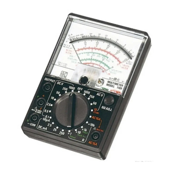
Page 10: Instrument Layout
4. Instrument Layout Meter Pointer Meter Zero Adjust Screw OUTPUT Terminal +(P) Terminal -COM (N) Terminal Front Panel Mirrored Scale Plate Meter Window Housing Case Ohm Zero Adjust Knob Range Selector Switch... -
Page 11: How To Read Scales
5. How to Read Scales H o w Measuring input Scales Read Ranges Terminals Scales 0.1V B 10 X0.01 0.5V X0.01 2.5V B 250 X0.01 DC Voltage B 10 +& COM (7 ranges) 250V B250 1000V X100 AC Voltage +& COM (4 ranges) 250V B250... - Page 12 Low Frequency Output Using B 50 Output & OUTPUT Terminal 250V B 250 (4 ranges) 1000V X 100 G 10-+22dB Low Frequency + & COM or G 10-+22dB X1 + 14dB Output (dB) Output & 250V G 10-+22dB X1 + 28dB (4 ranges) 1000V G 10-+22dB...
-
Page 13: Operating Instructions
6. Operating Instructions 6-1. Preparation ● Make certain that the batteries are installed into the battery case with polarity in correct position. Also, make sure that the fuses are properly installed. ● The test leads are safety designed, but make sure that they are securely connected to the instrument before use. -
Page 14: Dc Voltage Measurements
6-2. DC Voltage Measurements # WARNING When measuring a high voltage greater than 250V, turn off power to the circuit under test 8.nd follow the steps as described below. Then, turn on power to the circuit being measured and proceed with the voltage measurements. -
Page 15: Ac Voltage Measurements
6-3. AC Voltage Measurements # WARNING When measuring a high voltage greater than 250V, turn off power to the circuit under test and follow the steps (1) to (3) as outlined below. Then, turn off power to the circuit under test and proceed with the voltage measurements. -
Page 16: Low Frequency (Db) Measurements
6-4. Low Frequency Output (dB) Measurements Applications: Measuring the ratio of output to input for amplifiers, transmission circuits, etc. The ratio of output to input in amplifier and transmission circuits is expressed in logarithmic values as the human sense of hearing responds to the level of sound logarithmically. -
Page 17: Terminal
6-5. Low Frequency Output Measurements Using Output Terminal # WARNING When measuring a high voltage greater than 250V, turn off power to the circuit under test once and then follow the steps (1) to (3) as described for AC voltage measurements. Then, turn on power to the circuit and proceed with Low Frequency Output measurements. -
Page 18: Dc Current Measurements
The 1109S has a capacitor in series with the OUTPUT terminal. This OUTPUT terminal is useful for measuring the AC component only of a DC coupled Low Frequency Output in TV sets, audio equipment circuits, etc. by blocking the DC component. Insert the red test lead into the OUTPUT terminal and the black test lead into the -COM terminal. -
Page 19: Resistance Measurements
Applications: Measuring currents in DC operated electrical appliances, bias current of transitors, IC's, etc. Insert the red test lead into the + termin~1 and the black test lead into the COM terminal. Set the range selector switch to the 250mA range position. Turn off power to the circuit under test. - Page 20 # CAUTION Make the zero ohm adjustment after every change of the measuring range to obtain a more accurate reading. Application: Checking a resistance value of resistors, circuit continuity, short and open circuits, etc. Insert the red test lead into the +terminal and the black test lead into the COM terminal.
- Page 21 Notes: Fig. 3 shows the resistance measuring circuit. The positive (+) polarity of the battery is connected to the positive (+) terminal of meter. Therefore, the polarity of the terminals is reversed for resistance measurements, with output voltage from the -COM terminal being positive (+) and output voltage from the +terminal negative (-).
-
Page 22: Terminal Current Li, Terminal Voltage Lv
6-8. Terminal Current LI, Terminal Voltage LV &Diode Test # CAUTION Do not measure the internal resistance of a diode with low reverse withstand voltage using x 10kΩ range. The 12V voltage to be applied at this test could damage the diode. Check the rating of a diode before testing. - Page 23 The meter pointer deflects close to full scale when the forward current I is measured. However, it hardly deflects when the reverse current I is measured. The forward voltage of the average germanium diode measures 0.1 V to 0.2V and that of the silicon diode 0.5V to 0.8V. Since the maximum open circuit voltage at the low resistance ranges is 3V (12V at X 10k range), it is possible to light up an LED having a forward voltage of more than 1.5V and measure forward current I...
-
Page 24: Measuring I
6-9. Measuring I (leakage current of transistors) # CAUTION The leakage current does not change significantly according to voltage, but it rather exhibits constant current characteristics. However, note that the leakage current is very sensitive to the temperature and varies with the temperature change (approximately twice as against 10 ℃... - Page 25 Measuring Leakage Current of Transistor I EMITTER COLLECTOR BASE BASE P(+) P(+) COLLECTOR EMITTER N(-COM) N(-COM) NPN Type Transistor PNP Type Transistor Fig. 5 The leakage current of the silicon transistor is too small to give pointer deflection. If the pointer s h o u l d d e f l e c t , t h e likely cause would be some fault of the silicon...
-
Page 26: Measuring H
6-10. Measuring h (DC Current Amplification Factor) # CAUTION: With the germanium transistor, the leakage current flows into the collector side, causing that much error in leakage current measurements. Therefore, obtain a true value of leakage current by deducting a h value equivalent to the leakage current from the measured value. - Page 27 How to Use h Test Leads The test lead set mainly consisting of a resistor and a clip as shown in Fig. 8 is on the market and is recommended for use in making h measurements. Test Lead Set for h Measurements R=24kΩ...
- Page 28 As indicated in Fig. 9, connect the h test lead (1) to the multimeter, according to the polarity of a transistor to be tested; N (-COM) terminal for the NPN type transistor or P (+) terminal for the PNP type transistor. Also, connect the h test lead (2) to the P(+) terminal for the NPN type transistor and the N ( COM) terminal for the PNP type transistor.
-
Page 29: Fuse & Battery Replacement
7. Fuse & Battery Replacement # WARNING Never replace the fuse or batteries during measurements. Make sure to set the range selector switch to OFF position and remove the test leads from the instrument before replacing the fuse and batteries. Always use the F 2S0V 0.5A fuse as specified. - Page 30 PCB Component Layout Drawing Fig. 11...
- Page 31 PARTS LIST DESCRIPTION Resistor 1/2WF, 15MΩ) DC 1000 Resistor 1/4WF, 4MΩ) DC 250 Resistor 1/4WF, ( 800 KΩ) Resistor 1/4WF, ( 150 KΩ) Resistor 1/4WF, 40KΩ) Resistor 1/2WF, 8KΩ) Resistor 1/2WF, ( 83.3 KΩ) Resistor 1/4WF, ( 360 KΩ) Resistor 1/4WF, 1.8MΩ) AC 250...
- Page 33 MEMO...
- Page 34 MEMO...
- Page 36 DISTRIBUTOR Kyoritsu reserves the rights to change specifications or designs described in this manual without notice and without obligations. 08-12 92-2025A...
Need help?
Do you have a question about the KEW 1109 and is the answer not in the manual?
Questions and answers