ASROCK IMB-185 User Manual
Hide thumbs
Also See for IMB-185:
- User manual (39 pages) ,
- Settings manual (2 pages) ,
- Settings manual (2 pages)

Subscribe to Our Youtube Channel
Related Manuals for ASROCK IMB-185


Summary of Contents for ASROCK IMB-185
-
Page 1: User Manual
IMB-185 User Manual Version 1.0 Published September 2015 Copyright©2015 ASRock INC. All rights reserved. -
Page 2: Copyright Notice
(including damages for loss of proits, loss of business, loss of data, interruption of business and the like), even if ASRock has been advised of the possibility of such damages arising from any defect or error in the documentation or product. -
Page 3: Table Of Contents
Contents 1 Introduction ............5 1.1 Package Contents ............5 1.2 Speciications ..............6 1.3 Motherboard Layout ............8 1.4 I/O Panel ............... 10 2 Installation ............11 2.1 Screw Holes ..............11 2.2 Pre-installation Precautions ........... 11 2.3 Installation of Memory Modules (DIMM) ......12 2.4 Expansion Slots ............ - Page 4 4 Software Support ..........40 4.1 Install Operating System ..........40 4.2 Support CD Information ..........40 4.2.1 Running Support CD ..........40 4.2.2 Drivers Menu ............40 4.2.3 Utilities Menu............40 4.2.4 Contact Information ..........40...
-
Page 5: Introduction
In case any modiications of this manual occur, the updated version will be available on ASRock website without further notice. You may ind the latest VGA cards and CPU support lists on ASRock website as well. ASRock website http://www.asrock.com If you require technical support related to this motherboard, please visit our website for speciic information about the model you are using. -
Page 6: Speciications
1.2 Speciications Form Dimensions Mini-ITX (6.7-in x 6.7-in) Factor ® Socket LGA1150 for Intel Core i7/i5/i3/Celeron (Haswell) Core (By CPU, Max 4) Processor Number System Max Speed (By CPU) L3 Cache (By CPU) Chipset BIOS UEFI Mini-PCIe Expansion mSATA Slot PCIe 1 (x16) CFast Card... - Page 7 4 (2 x USB 3.0, 2 x USB 2.0) Audio 2 (Mic-In, Line-Out) Serial 3 (RS-232/422/485) PS/2 6 (3 x USB Header 2.54mm pitch) LVDS/ 24 bit dual channel LVDS Inverter Serial 3 (RS-232) SATA 2 x SATA3 (6.0Gb/s), 2 x SATA2 (3.0Gb/s) mPCIe Internal Parallel...
-
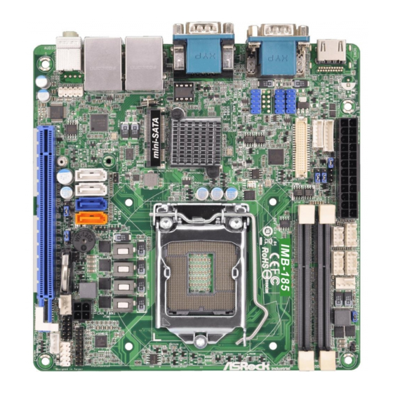
Page 8: Motherboard Layout
1.3 Motherboard Layout 4 5 6 ATXPWR1 COM4 COM6 BLT_VOL1 PNL_PWR1 CPU_FAN1 PS2_KB_MS1 COM5 BKT_PWR1 DDR3_B1 BLT_PWR1 BLT_PWM1 DDR3_A1 USB10_11 IMB-185 USB8_9 USB4_5 BIOS Chip mini-SATA USB 3.0 T: USB1 LAN1 B: USB0 USB 2.0 T: USB3 LAN2 B: USB2 MSATA_SEL1 CON1... - Page 9 1 : Backlight Power Connector 2 : Backlight Volume Control 3 : 24-pin ATX Power Input Connector 4 : PNL_PWR1 5 : Backlight Power Selection 6 : BLT_PWM1 7 : PS2_KB_MS1 8 : RS-232 Port 4 Pin Headers 9 : 4-Pin Chassis FAN Connector (+12V) 10 : Chassis Intrusion Headers 11 : 4-pin ATX Power Input Connector 12 : TPM Header...
-
Page 10: I/O Panel
1.4 I/O Panel COM Port (COM1)* USB 2.0 Ports (USB_23) COM Port (COM3)* USB 3.0 Ports (USB_01) LAN RJ-45 Port (LAN1)** VGA Port (VGA1) LAN RJ-45 Port (LAN2)** COM Port (COM2)* Line out (Lime) HDMI Port (HDMI1) Microphone (Pink) * This motherboard supports RS232/422/485 on COM1~3 ports. Please refer to below table for the pin deinition. -
Page 11: Installation
Chapter 2: Installation This is a Mini-ITX form factor (6.7" x 6.7", 17.0 x 17.0 cm) motherboard. Before you install the motherboard, study the coniguration of your chassis to ensure that the motherboard its into it. Make sure to unplug the power cord before installing or removing the motherboard. -
Page 12: Installation Of Memory Modules (Dimm)
2.3 Installation of Memory Modules (SO-DIMM) This motherboard provides two 204-pin DDR3 (Double Data Rate 3) SO-DIMM slots. It is not allowed to install a DDR or DDR2 memory module into DDR3 slot; otherwise, this motherboard and SO-DIMM may be damaged. Installing a SO-DIMM Please make sure to disconnect power supply before adding or removing SO-DIMMs or the system components. -
Page 13: Expansion Slots
2.4 Expansion Slots (PCI Express and mini-SATA Slots) There is 1 PCI Express slot and 1 mini-SATA slot on this motherboard. PCIE slots: PCIE1 (PCIE x16 slot; Blue) is used for PCI Express x16 lane width graphics cards. MINI_PCIE1 (mini-SATA slot) is used for mSATA cards. Installing an expansion card Step 1. -
Page 14: Jumpers Setup
2.5 Jumpers Setup The illustration shows how jumpers are setup. When the jumper cap is placed on pins, the jumper is “Short”. If no jumper cap is placed on pins, the jumper is “Open”. The illustration shows a 3-pin jumper whose pin1 and pin2 are “Short”... - Page 15 Digital Input / Output Power Select 1-2 : +12V 2-3 : +5V (3-pin JGPIO_PWR1) (see p.8, No. 17) GPIO Default Setting 1-2 : +5V 2-3 : GND (3-pin JGPIO_JP1) (see p.8, No. 18) mSATA Select Open : Use SATA_5 Close : Use mSATA (2-pin MSATA_SEL1) (see p.8, No.
-
Page 16: Onboard Headers And Connectors
2.6 Onboard Headers and Connectors Onboard headers and connectors are NOT jumpers. Do NOT place jumper caps over these headers and connectors. Placing jumper caps over the headers and connectors will cause permanent damage of the motherboard! LVDS Panel Connector Signal Name Signal Name (40-pin LVDS1) - Page 17 CPU Fan Connector Please connect the CPU fan cable to the connector and (4-pin CPU_FAN1) +12V match the black wire to the CPU_FAN_SPEED (see p.8 No. 9) FAN_SPEED_CONTROL ground pin. Though this motherboard provides 4-Pin CPU fan (Quiet Fan) support, the 3-Pin CPU fan still can work successfully even without the fan speed control function.
- Page 18 Digital Input / Output Pin Header PIN Signal Name PIN Signal Name (10-pin JGPIO1) SIO_GP24 SIO_GP20 (see p.8, No. 15) SIO_GP25 SIO_GP21 SIO_GP26 SIO_GP22 SIO_GP27 SIO_GP23 JGPIO_PWR1 10 System Panel Header This header accommodates PLED+ PLED- several system front panel (9-pin PANEL1) PWRBTN# functions.
- Page 19 SATA2 Connectors These two Serial ATA2 (SATA2) connectors support SATA data (SATA_4/SATA_5: see p.8, No. 22) cables for internal storage devices. The current SATA2 interface allows up to 3.0 Gb/s data transfer rate. SATA3 Connectors These two Serial ATA3 (SATA3) connectors support SATA data (SATA_0/SATA_1: see p.8, No.
- Page 20 Front Panel Audio Header This is an interface for front panel audio cable that allows (9-pin HD_AUDIO1) convenient connection and (see p.8 No. 23) control of audio devices. 3W Audio Amp Output Wafer Signal Name (4-pin SPEAKER1) SPK L- (see p.8, No. 14) SPK L+ SPK R+ SPK R-...
-
Page 21: Driver Installation Guide
Driver Installation Guide To install the drivers to your system, please insert the support CD to your optical drive irst. Then, the drivers compatible to your system can be auto-detected and listed on the support CD driver page. Please follow the order from top to bottom to install those required drivers. -
Page 22: Uefi Setup Utility
Chapter 3: UEFI SETUP UTILITY 3.1 Introduction This section explains how to use the UEFI SETUP UTILITY to conigure your system. The UEFI chip on the motherboard stores the UEFI SETUP UTILITY. You may run the UEFI SETUP UTILITY when you start up the computer. Please press <F2>... -
Page 23: Navigation Keys
3.1.2 Navigation Keys Please check the following table for the function description of each navigation key. Navigation Key(s) Function Description Moves cursor left or right to select Screens Moves cursor up or down to select items + / - To change option for the selected items <Enter>... -
Page 24: Advanced Screen
3.3 Advanced Screen In this section, you may set the conigurations for the following items: CPU Conigu- ration, Chipset Coniguration, Storage Coniguration, Intel(R) Smart Connect Tech- nology, Super IO Coniguration, ACPI Coniguration, USB Coniguration and Voltage Coniguration. Setting wrong values in this section may cause the system to malfunction. -
Page 25: Cpu Coniguration
3.3.1 CPU Coniguration Active Processor Cores Select the number of cores to enable in each processor package. CPU C States Support Enable CPU C States Support for power saving. It is recommended to keep C3, C6 and C7 all enabled for better power saving. Enhanced Halt State (C1E) Enable Enhanced Halt State (C1E) for lower power consumption. - Page 26 Intel Turbo Boost Technology Use this item to enable or disable Intel Turbo Boost Mode Technology. Turbo Boost Mode allows processor cores to run faster than marked fre- quency in speciic conditions. The default value is [Enabled]. CPU Thermal Throttling You may select [Enabled] to enable CPU internal thermal control mechanism to keep the CPU from overheating.
-
Page 27: Chipset Coniguration
3.3.2 Chipset Coniguration DRAM Frequency If [Auto] is selected, the motherboard will detect the memory module(s) inserted and assign the appropriate frequency automatically. Primary Graphics Adapter This allows you to select [Onboard] or [PCI Express] as the boot graphic adapter priority. The default value is [PCI Express]. VT-d ®... - Page 28 Front Panel Select [Auto] or [Disabled] for the onboard HD Audio Front Panel. Onboard HDMI HD Audio This allows you to enable or disable the Onboard HDMI HD Audio feature. Onboard LAN1 This allows you to enable or disable the Onboard LAN1 feature. Onboard LAN2 This allows you to enable or disable the Onboard LAN2 feature.
-
Page 29: Storage Coniguration
3.3.3 Storage Coniguration SATA Controller(s) Use this item to enable or disable the SATA Controller feature. SATA Mode Selection Use this to select SATA mode. Coniguration options: [IDE Mode], [AHCI Mode] and [Disabled]. The default value is [AHCI Mode]. AHCI (Advanced Host Controller Interface) supports NCQ and other new features that will improve SATA disk perfor- mance but IDE mode does not have these advantages. -
Page 30: Intel(R) Smart Connect Technology
3.3.4 Intel(R) Smart Connect Technology Intel(R) Smart Connect Technology Use this item to enable or disable Intel(R) Smart Connect Technology. Intel(R) Smart Connect Technology keeps your e-mail and social networks, such as Twitter, Facebook, etc. updated automatically while the computer is in sleep mode. -
Page 31: Super Io Coniguration
3.3.5 Super IO Coniguration COM1 Coniguration Use this to set parameters of COM1. Select COM1 port type: [RS232], [RS422] or [RS485]. COM2 Coniguration Use this to set parameters of COM2. Select COM2 port type: [RS232], [RS422] or [RS485]. COM3 Coniguration Use this to set parameters of COM3. -
Page 32: Acpi Coniguration
3.3.6 ACPI Coniguration Suspend to RAM Use this item to select whether to auto-detect or disable the Suspend-to- RAM feature. Select [Auto] will enable this feature if the OS supports it. Check Ready Bit Use this item to enable or disable the feature Check Ready Bit. ACPI HPET Table Use this item to enable or disable ACPI HPET Table. -
Page 33: Usb Coniguration
3.3.7 USB Coniguration USB Controller Use this item to enable or disable the use of USB controller. Intel USB 3.0 Mode Use this item to enable or disable the use of Intel USB 3.0 mode. Legacy USB Support Use this option to select legacy support for USB devices. There are four coniguration options: [Enabled], [Auto], [Disabled] and [UEFI Setup Only]. -
Page 34: Voltage Coniguration
3.3.8 Voltage Coniguration DRAM Voltage Use this to select DRAM Voltage. The default value is [1.50V]. -
Page 35: Hardware Health Event Monitoring Screen
3.4 Hardware Health Event Monitoring Screen In this section, it allows you to monitor the status of the hardware on your system, including the parameters of the CPU temperature, motherboard temperature, CPU fan speed, chassis fan speed, and the critical voltage. CPU_FAN1 Setting This allows you to set CPU fan 1’s speed. -
Page 36: Boot Screen
3.5 Boot Screen In this section, it will display the available devices on your system for you to conig- ure the boot settings and the boot priority. Boot From Onboard LAN Use this item to enable or disable the Boot From Onboard LAN feature. Setup Prompt Timeout This shows the number of seconds to wait for setup activation key. - Page 37 Enable to launch the Compatibility Support Module. Please do not disable ® unless you’re running a WHCK test. If you are using Windows 8 64-bit and all of your devices support UEFI, you may also disable CSM for faster boot speed. Launch PXE OpROM Policy Select UEFI only to run those that support UEFI option ROM only.
-
Page 38: Security Screen
3.6 Security Screen In this section, you may set, change or clear the supervisor/user password for the system. Secure Boot Use this to enable or disable Secure Boot. The default value is [Disabled]. -
Page 39: Exit Screen
3.7 Exit Screen Save Changes and Exit When you select this option, it will pop-out the following message, “Save coniguration changes and exit setup?” Select [OK] to save the changes and exit the UEFI SETUP UTILITY. Discard Changes and Exit When you select this option, it will pop-out the following message, “Discard changes and exit setup?”... -
Page 40: Software Support
Click on a speciic item then follow the installation wizard to install it. 4.2.4 Contact Information If you need to contact ASRock or want to know more about ASRock, you’re welcome to visit ASRock’s website at http://www.asrock.com; or you may con-...
Need help?
Do you have a question about the IMB-185 and is the answer not in the manual?
Questions and answers