ASROCK IMB-185 Settings Manual
Jumpers and headers setting guide
Hide thumbs
Also See for IMB-185:
- User manual (39 pages) ,
- User manual (40 pages) ,
- Settings manual (2 pages)
Table of Contents
Advertisement
Quick Links
IMB-185
32
The terms HDMI™ and HDMI High-Definition
Multimedia Interface, and the HDMI logo are
trademarks or registered trademarks of HDMI
Licensing LLC in the United States and other
31
countries.
30
29
28
27
26
25
1 : Backlight Power Connector
PIN
Signal Name
1
GND
2
GND
3
BL CTL
4
BL EN
5
LCD_BLT_VCC
6
LCD_BLT_VCC
2 : Backlight Volume Control
PIN
Signal Name
1
GPIO_VOL_UP
2
GPIO_VOL_DW
3
PWRDN
4
LVDS1 BLUP
5
LVDS1 BLDW
6
GND
7
GND
3 : 24-pin ATX Power Input Connector
4 : PNL_PWR1
1-2: LVDD: +3V
2-3: LVDD: +5V
4-5: LVDD: +12V
5 : Backlight Power Selection
1-2: +5V
2-3: +12V
All manuals and user guides at all-guides.com
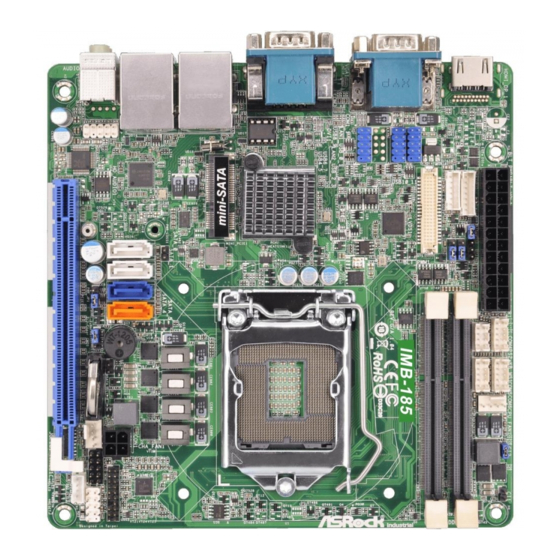
Jumpers and headers setting guide
1 2
3
ATXPWR1
BLT_VOL1
PNL_PWR1
1
1
BKT_PWR1
BLT_PWR1
1
BLT_PWM1
1
1
USB10_11
1
USB8_9
1
USB4_5
1
BIOS
Chip
mini-SATA
USB 3.0
T: USB1
LAN1
B: USB0
PWR_LOSS1
1
USB 2.0
T: USB3
LAN2
B: USB2
1
24
23
22
6 : BLT_PWM1
1-2: +3V Level
2-3: +5V Level
1
7 : PS2_KB_MS1
PIN
Signal Name
1
KBCLK
2
+5V
3
KBDATA
4
+5V
5
MSDATA
6
GND
7
MSCLK
1
8
GND
8 : COM4, 5, 6 Headers (RS232)
PIN Signal Name PIN
Signal Name
1
DCD
6
DSR
2
RXD
7
RTS
3
TXD
8
CTS
4
DTR
9
No Power/+5V/+12V
5
GND
10
9 : 4-Pin Chassis FAN Connector (+12V)
GND
+12V
CPU_FAN_SPEED
FAN_SPEED_CONTROL
10 : Chassis Intrusion Headers
CI1:
Close: Active case open
Open: Normal
Cl2:
Close: Normal
Open: Active case open
4 5 6
7
8
9
1
1
COM4
COM6
1
1
CPU_FAN1
PS2_KB_MS1
COM5
DDR3_B1
DDR3_A1
IMB-185
BUZZ1
JGPIO_JP1
JGPIO_PWR1
MSATA_SEL1
1
1
1
CLRCOMOS1
PWR_JP1
CMOS
1
1
Battery
CHA_FAN1
PCIE1
21
20
19
18
17
16
11 : 4-pin ATX Power Input Connector
12 : TPM Header
1
13 : System Panel Header
14 : 3W Audio AMP Output Wafer
PIN
1
1
2
3
2
4
NC
15 : Digital Input / Output
Pin Header
PIN Signal Name PIN Signal Name
1
3
5
7
9
JGPIO_PWR1 10
16 : 4-Pin Chassis FAN Connector (+12V)
10
1
1
CI2
CI1
11
CON1
12
1
TPM1
PLED PWRBTN
13
1
1
JGP IO1
HDLED RESET
PANEL 1
1
SPEAKER1
15
14
1
Signal Name
1
SPK L-
SPK L+
SPK R+
SPK R-
SIO_GP24
2
SIO_GP20
SIO_GP25
4
SIO_GP21
SIO_GP26
6
SIO_GP22
SIO_GP27
8
SIO_GP23
GND
CHA_FAN_SPEED
+12V
FAN_SPEED_CONTROL
GND
Advertisement
Table of Contents

Related Manuals for ASROCK IMB-185


Summary of Contents for ASROCK IMB-185
- Page 1 All manuals and user guides at all-guides.com Jumpers and headers setting guide IMB-185 4 5 6 ATXPWR1 COM4 COM6 BLT_VOL1 PNL_PWR1 CPU_FAN1 PS2_KB_MS1 COM5 The terms HDMI™ and HDMI High-Definition BKT_PWR1 DDR3_B1 BLT_PWR1 Multimedia Interface, and the HDMI logo are...
- Page 2 All manuals and user guides at all-guides.com 4 5 6 ATXPWR1 COM4 COM6 BLT_VOL1 PNL_PWR1 CPU_FAN1 PS2_KB_MS1 COM5 BKT_PWR1 DDR3_B1 BLT_PWR1 BLT_PWM1 DDR3_A1 USB10_11 IMB-185 USB8_9 USB4_5 BIOS Chip mini-SATA USB 3.0 T: USB1 LAN1 B: USB0 PWR_LOSS1 USB 2.0 T: USB3 LAN2 B: USB2 CON1...
Need help?
Do you have a question about the IMB-185 and is the answer not in the manual?
Questions and answers