Toro Greensmaster 3420 TriFlex Operator's Manual
Hide thumbs
Also See for Greensmaster 3420 TriFlex:
- Operator's manual (56 pages) ,
- Service manual (360 pages) ,
- Manual (334 pages)

Related Manuals for Toro Greensmaster 3420 TriFlex


Summary of Contents for Toro Greensmaster 3420 TriFlex
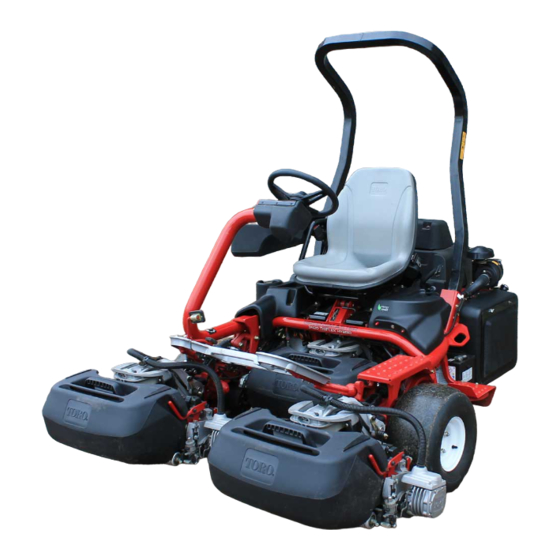
- Page 1 Form No. 3377-360 Rev A Greensmaster ® 3420 TriFlex™ Traction Unit Model No. 04540—Serial No. 313000001 and Up g014597 *3377-360* A Register at www.Toro.com. Original Instructions (EN)
-
Page 2: Introduction
You are responsible for operating the product properly and safely. This manual also uses 2 words to highlight information. You may contact Toro directly at www.Toro.com for product Important calls attention to special mechanical information and accessory information, help finding a dealer, or to register and Note emphasizes general information worthy of special your product. -
Page 3: Table Of Contents
Adjusting the Transport Speed .........41 Safety ................4 Adjusting the Mowing Speed........42 Safe Operating Practices........... 4 Cooling System Maintenance ........42 Toro Mower Safety ..........5 Cleaning the Radiator Screen........42 Sound Power Level ..........6 Brake Maintenance ............43 Sound Pressure Level..........7 Adjusting the Brakes ..........43... -
Page 4: Safety
Preparation Safety • While mowing, always wear substantial footwear, long trousers, hard hat, safety glasses, and hearing protection. This machine meets or exceeds CEN standard EN Long hair, loose clothing, or jewelry may get tangled 836:1997, ISO standard 5395:1990, and ANSI B71.4-2004 in moving parts. -
Page 5: Maintenance And Storage
• Slow down and use caution when making turns and crossing roads and sidewalks. Stop the reels when not The following list contains safety information specific to Toro mowing. products or other safety information that you must know that is not included in the ANSI standards. -
Page 6: Sound Power Level
• • Shut the engine off before emptying the baskets. To ensure safety and accuracy, have an Authorized Toro Distributor check the maximum engine speed with a • Raise the cutting units when driving from one work area tachometer. -
Page 7: Sound Pressure Level
Sound Pressure Level Measured vibration level for left hand = 0.52 m/s Uncertainty Value (K) = 0.26 m/s This unit has a sound pressure level at the operator’s ear of 84 dBA, which includes an Uncertainty Value (K) of 1 dBA. Measured values were determined according to the procedures outlined in EN 836. - Page 8 115-8156 1. Reel height 3. 8 Blade cutting unit 5. 14 Blade cutting unit 7. Fast 2. 5 Blade cutting unit 4. 11 Blade cutting unit 6. Reel speed 8. Slow 121–6670 1. Engage the reels. 2. Disengage the reels. 115-8155 1.
- Page 9 121–5169 1. Throttle—slow 5. Functional control lever 9. Use for mowing 2. Throttle—continuous variable setting 6. Lower the reels and engage. 10. Use for transport 3. Throttle—fast 7. Use for backlapping reels 4. Raise the reels 8. Neutral 121–5171 Battery Symbols 1.
- Page 10 121–2641 121–2640 1. Warning—read the 4. Tipping hazard—slow 1. Warning—read the 4. Tipping hazard—do not Operator’s Manual, do machine before turning, Operator’s Manual, do drive across slopes greater not operate this machine do not turn at high speeds. not operate this machine than 15 degrees or down unless you are trained.
-
Page 11: Setup
Setup Loose Parts Use the chart below to verify that all parts have been shipped. Procedure Description Qty. Roll bar Bolt (1/2 x 3-3/4 inches) Install the roll bar. Flange-nut (1/2 inch) Seat completion kit Install the seat to the base. Steering wheel Locknut (1-1/2 inches) Install the steering wheel. -
Page 12: Installing The Roll Bar
Installing the Roll Bar Installing the Seat Parts needed for this procedure: Parts needed for this procedure: Seat completion kit Roll bar Bolt (1/2 x 3-3/4 inches) Procedure Flange-nut (1/2 inch) Acquire your desired seat kit from your distributor and install it as directed in the instruction included with the kit. -
Page 13: Activating And Charging The Battery
Activating and Charging the Battery No Parts Required Procedure Use only electrolyte (1.265 Specific Gravity) to fill battery Figure 6 initially. 1. Electrolyte 1. Remove the fasteners and battery clamp and lift out the battery. 4. Allow approximately 20 to 30 minutes for the Important: Do not add electrolyte while the electrolyte to soak into the plates. -
Page 14: Installing The Grass Basket Hooks
WARNING Battery terminals or metal tools could short against metal tractor components causing sparks. Sparks can cause the battery gasses to Installing the Grass Basket explode, resulting in personal injury. Hooks • When removing or installing the battery, do not allow the battery terminals to touch any metal parts of the tractor. - Page 15 2. Apply grease to the inside diameter of the drive coupler. 3. The cutting unit is shipped without a front roller. Obtain a roller (Model No. 04625, 04626 or 04627) from your local Toro Distributor. Install the roller using the loose parts supplied with the cutting unit and g014602 installation instructions included with the roller.
-
Page 16: Adding Rear Weight
9. With the latches on the suspension-arm bar pointing up (i.e., open) (Figure 12), push the suspension arm down so that the bar fits over the bar across the top of the cutting unit (Figure 13). g014609 Figure 12 1. Latch—closed position 3. -
Page 17: Installing Eu Decals
Product Overview Installing EU Decals Parts needed for this procedure: Warning decal 121–2640 Procedure If this machine will be used in the EU, affix the warning decal 121–2640 over warning decal 121–2641. g014674 Figure 15 1. Engine 5. Steering wheel 2. -
Page 18: Ignition Switch
Note: The engine cannot be stopped by the use of the throttle control. g014603 Figure 16 1. Traction pedal—forward 3. Steering arm locking pedal G017975 2. Traction pedal—reverse Figure 18 1. Ignition switch 4. Throttle 2. Functional control lever 5. InfoCenter 3. - Page 19 conjunction with the raise/lower mow control lever and the reel speed control for backlapping the reels. 1200 52.2V n/min 1600 10,000.0 n/min G017943 G017947 Figure 19 Figure 21 1. Backlap switch—backlap 2. Backlap switch—mow 1. Functional control status 3. PTO speed position position 2.
- Page 20 Controls the units used on the a list of the recent machine InfoCenter. The menu choices faults. Refer to the Service are English or Metric. Manual or your Authorized Toro Language Controls the language used on Distributor for more information the InfoCenter.
- Page 21 0.400 Note: If the user defined passcode is forgotten, a temporary 0.450 passcode can be obtained through your authorized Toro distributor. Setting the Reel Speed Diagnosing the Fault Log Indicator To achieve a consistent, high quality–of–cut and a uniform...
- Page 22 Parking Brake Lever Pull up on the brake lever (Figure 16) to set the parking brake. Disengage it by pushing it forward and down. Set the parking brake any time you leave the machine. g014628 Figure 24 1. Seat adjusting lever g01461 0 Figure 23 Note: Before lifting the seat, slide it to the furthest back...
-
Page 23: Specifications
Cutting Unit Power Disconnect its capabilities. Contact your Authorized Service Dealer or Distributor or go to www.Toro.com for a list of all approved Connectors attachments and accessories. Before installing, removing, or working on the cutting units, disconnect the cutting units from the power supply... -
Page 24: Operation
Preferred oil: SAE 10W–30 • Alternate oil: SAE 15W–40 Toro Premium Engine oil is available from your distributor in the 10W–30 viscosity. See the parts catalog for part numbers. Note: The best time to check the engine oil is when the engine is cool before it has been started for the day. -
Page 25: Filling The Fuel Tank
Filling the Fuel Tank • Fuel filter plugging may be expected for a time after converting to biodiesel blends. Use only clean, fresh diesel fuel or biodiesel fuels with low • Contact your distributor if you wish for more information (<500 ppm) or ultra low (<15 ppm) sulfur content. -
Page 26: Checking The Cooling System
the coolant at the beginning of each day before starting the engine. CAUTION If the engine has been running, the pressurized, hot coolant can escape and cause burns. • Do not open the radiator cap when the engine is running. •... - Page 27 Filling the Hydraulic Tank Toro Premium All Season Hydraulic Fluid (Available in 5 gallon pails or 55 gallon drums. See parts catalog or Toro 1. Position the machine on a level surface. Make sure the distributor for part numbers.) machine has cooled down so the oil is cold.
-
Page 28: Draining Water From The Fuel Filter
Draining Water from the Fuel Checking the Reel-to-Bedknife Filter Contact Each day before operating the machine, check the Service Interval: Before each use or daily reel-to-bedknife contact, regardless if the quality of cut had 1. Position the machine on a level surface and stop the previously been acceptable. -
Page 29: Checking The Safety Interlock System
2. Remove your foot from the traction pedal and make The safety interlock system prevents the engine from starting sure the pedal is in the neutral position. unless: 3. Move the throttle lever to the Slow position. • The traction pedal is in neutral. 4. -
Page 30: Installing And Removing The Cutting Units
Installing and Removing the Cutting Units Installing the Cutting Units 1. Disconnect the cutting unit power disconnect couplers; refer to Cutting Unit Power Disconnect Connectors (page 23). g014609 Figure 36 CAUTION 1. Latch—closed position 3. Latch—open position If you do not disconnect the power to the 2. - Page 31 Figure 39 1. Reel motor 2. Motor retaining bar 4. Move the motor to the storage location on the front of the suspension arm (Figure 40). Figure 38 1. Reel motor 3. Cavity 2. Spline shaft 4. Motor retaining bar 8.
-
Page 32: Training Period
7. Roll the cutting unit out from under the suspension arm. 8. Repeat steps 3 through 7 for the other cutting units as required. 9. Connect the cutting unit power disconnect couplers; refer to Cutting Unit Power Disconnect Connectors (page 23). Training Period Before mowing greens with the machine, it is recommended that you find a clear area and practice starting and stopping,... -
Page 33: Transport Operation
Towing the Machine In case of an emergency the machine can be towed for a short distance (less than 1/4 mile (0.4 km)). However, Toro does not recommend this as standard procedure. Important: Do not tow the machine faster than 2-3 MPH (3-5 km/h) because the drive system may be damaged. -
Page 34: Maintenance
Maintenance Note: Determine the left and right sides of the machine from the normal operating position. CAUTION If you leave the key in the ignition switch, someone could accidently start the engine and seriously injure you or other bystanders. Remove the key from the ignition. Recommended Maintenance Schedule(s) Maintenance Service Maintenance Procedure... -
Page 35: Daily Maintenance Checklist
Daily Maintenance Checklist Duplicate this page for routine use. Maintenance Check Item For the week of: Mon. Tues. Wed. Thurs. Fri. Sat. Sun. Check the safety interlock operation. Check the instrument operation Check the brake operation. Check the fuel filter/water separator. -
Page 36: Lubrication
Lubrication Engine Maintenance Servicing the Air Cleaner Greasing the Generator Belt Tensioner Service Interval: Every 200 hours • Check the air cleaner body for damage which could cause Service Interval: Every 400 hours an air leak. Replace if damaged. Check the whole intake system for leaks, damage or loose hose clamps. -
Page 37: Changing The Engine Oil And Filter
4. Clean the dirt ejection port located in the removable 3. Screw the filter on by hand until the gasket contacts cover. Remove the rubber outlet valve from the cover, the filter adapter, then tighten 1/2 to 3/4 turn further. clean the cavity and replace the outlet valve. -
Page 38: Fuel System Maintenance
Fuel System Maintenance Fuel Filter/Water Separator Service Interval: Every 800 hours Servicing the Filter 1. Close the fuel shut off valve (Figure 47) below the fuel tank. g014720 Figure 48 1. Fuel filter /water separator 2. Filter drain plug canister 5. -
Page 39: Electrical System Maintenance
Electrical System WARNING Maintenance Battery terminals or metal tools could short against metal tractor components causing sparks. Sparks can cause the battery gasses to explode, resulting Servicing the Battery in personal injury. • When removing or installing the battery, do not allow the battery terminals to touch any metal WARNING parts of the tractor. -
Page 40: Fuses
Fuses The fuses in the machine’s electrical system are located under the seat (Figure 49). Figure 50 1. Alternate positive battery post g014617 Figure 49 1. Fuses 2. 50 A fuse for radiator fan (behind parts illustrated) Fuse Layout Lift Reel Starter E-Reel Enable Over Temp... -
Page 41: Drive System Maintenance
Adjusting the Transport Speed Drive System Maintenance The traction pedal is adjusted for maximum transport speed at the factory, but an adjustment may be required if the pedal reaches full stroke before it contacts the pedal stop, or if a decrease in transport speed is desired. -
Page 42: Adjusting The Mowing Speed
Adjusting the Mowing Speed Cooling System Maintenance The machine is adjusted at the factory, but speed may be varied if desired. 1. Loosen the jam nut on the trunnion bolt (Figure 53). Cleaning the Radiator Screen 2. Loosen the nut securing the lock and mow brackets on the pedal pivot. -
Page 43: Brake Maintenance
Brake Maintenance Belt Maintenance Adjusting the Brakes Adjusting the Alternator Belt If the brake fails to hold the machine while parked, you can Service Interval: After the first 8 hours adjust the brakes using the bulkhead fitting near the brake Make sure the belt is properly tensioned to ensure proper drum;... -
Page 44: Hydraulic System Maintenance
Every 800 hours and fittings are tight before applying pressure to the hydraulic system. If the oil becomes contaminated, contact your local Toro distributor because the system must be flushed. Contaminated • Keep your body and hands away from pin oil looks milky or black when compared to clean oil. -
Page 45: Cutting Unit Maintenance
Cutting Unit Maintenance Raise/Lower Mow control rearward and stop the engine. After completing adjustments, repeat steps 4 through 9. Backlapping the Reels 12. Repeat the procedure for all cutting units you want to backlap. WARNING 13. When finished, return the backlap switch to the forward (F) position, replace the cover, and wash all lapping Contact with the reels or other moving parts can compound off of the cutting units. -
Page 46: Storage
Storage If you wish to store the machine for a long period of time, the following steps should be performed prior to storage: 1. Remove accumulations of dirt and old grass clippings. Sharpen the reels and bedknives, if necessary; refer to the Cutting Unit Operator's Manual. -
Page 47: Schematics
Schematics Electric Reel Schematic (Rev. A) - Page 48 G015569 Electrical Schematic (Rev. A)
- Page 49 G020719 Hydraulic Schematic (Rev. A)
- Page 50 Notes:...
- Page 51 Notes:...
-
Page 52: The Toro Total Coverage Guarantee
Countries Other than the United States or Canada Customers who have purchased Toro products exported from the United States or Canada should contact their Toro Distributor (Dealer) to obtain guarantee policies for your country, province, or state. If for any reason you are dissatisfied with your Distributor's service or have difficulty obtaining guarantee information, contact the Toro importer.
Need help?
Do you have a question about the Greensmaster 3420 TriFlex and is the answer not in the manual?
Questions and answers
No activan los molinetes
The reels on the Toro Greensmaster 3420 TriFlex may not be activating due to issues with the 48V electrical system, which powers the reel motors. Possible causes include:
1. Faulty Generator – The engine-driven generator supplies 48V DC power to the reel motors. If it is not functioning properly, the reels will not receive power.
2. Blown Fuses – The 48V system has two fuses for circuit protection. If one or both fuses are blown, the reels will not activate.
3. Control Module Issues – The system relies on integral controllers in the generator and reel motors, along with the TEC machine controller. Communication failure between these components can prevent reel activation.
4. Isolation Module Failure – The isolation module ensures communication between the 12V TEC controller and 48V reel motors. A failure in this module can disrupt operation.
5. Location ID Module Issue – This module identifies reel motor positions. If it malfunctions, the machine may not detect the reels correctly.
6. Disconnected or Faulty Wiring – Since the 48V system is isolated and does not use the vehicle frame for grounding, damaged or disconnected wiring could cause power loss to the reels.
Checking these components systematically can help diagnose and resolve the issue.
This answer is automatically generated
No me prenden los molinetes
The Toro Greensmaster 3420 TriFlex reels may not turn on due to several possible reasons:
1. Fault 19: Stalled Reel Motor – If cutting unit 3 was at zero RPM for more than 3 seconds, the reel motor may lack sufficient torque. This could be due to excessive load, such as cutting grass longer than the machine's design allows.
2. Fault 15: High Temperature Warning – If this fault is present, it should be addressed first, as overheating can reduce reel speed and cause stalling.
3. Electrical Issues – A short detected in the reel motor wiring or a failure in the 48V power connection could prevent the reels from turning.
4. Motor Failure – If swapping cutting reel motors shows the fault follows a specific motor, it indicates a defective reel motor that needs replacement.
5. Starter/Generator Issues – If the wiring between the controller and the starter/generator is damaged, or if the starter/generator itself is faulty, the machine may not supply power to the reel motors.
To diagnose, check for fault codes, verify electrical connections, inspect for overheating, and test reel motors by swapping them between cutting units.
This answer is automatically generated