Table of Contents
Advertisement
Quick Links
Thank you for adopting Panasonic DATA ARCHIVER.
This document describes how the administrator manages the usage of the DATA
ARCHIVER.
Before using this unit, read "Cautions for regulations and safety/Overview/Disclaimers"
and observe the instructions in that document.
The DATA ARCHIVER LB-DH8 series includes the following modules and units.
Model Name
Base Module (Model Number: LB-DH80)
Bottom Module (Model Number: LB-DH81)
Extension Module (without the Writer Unit)
Extension Unit (Model Number: LB-XH82) and Control Unit (Model Number:
LB-XC82)
Extension Module (with the Writer Unit)
Extension Unit (Model Number: LB-XH82)
and Writer Unit (Model Number: LB-XD82)
Operator Guide
DATA ARCHIVER
Model No.
SAS interface model
iSCSI interface model
FC interface model
SAS interface model
iSCSI interface model
FC interface model
LB-DH8 series
Part Number
LB-DH80A0G
LB-DH80S0G
LB-DH80F0G
LB-DH81Z0G
LB-DH82Z0G
LB-DH82A0G
LB-DH82S0G
LB-DH82F0G
SQW0319
Advertisement
Table of Contents

Related Manuals for Panasonic LB-DH8 series


Summary of Contents for Panasonic LB-DH8 series
- Page 1 This document describes how the administrator manages the usage of the DATA ARCHIVER. Before using this unit, read “Cautions for regulations and safety/Overview/Disclaimers” and observe the instructions in that document. The DATA ARCHIVER LB-DH8 series includes the following modules and units. Model Name Part Number Base Module (Model Number: LB-DH80)
-
Page 2: Table Of Contents
Table of contents Introduction Overview of functions ......................4 System configuration..........................5 Host interface specifications ........................ 7 Component names........................8 Handling a magazine and magazine drawer................. 17 Magazine............................17 How the unit identifies a magazine ....................20 Magazine drawer..........................21 Removing a magazine from a magazine drawer................ - Page 3 Contacting your support service provider ..................138 Initializing settings upon transfer or disposal ................... 138 Disclaimer ............................138 Specifications ........................139 LB-DH8 series (common) ........................ 139 Base Module ............................ 140 Bottom Module..........................141 Extension Unit..........................142 Control Unit ............................142 Writer Unit ............................
-
Page 4: Introduction
The Panasonic DATA ARCHIVER LB-DH8 series is a high-capacity storage library device using optical discs. The basic system of the library device in the LB-DH8 series consists of the LB-DH80 Base Module and the LB-DH81 Bottom Module. The Base Module has a set of built-in drive systems for reading and writing data and can store up to 76 magazines. -
Page 5: System Configuration
Introduction Overview of functions System configuration Connect various ports of the unit to a power source and various servers according to the functions to be used. System configuration example Exclusive use connection cable DC cable I/O cable SAS/iSCSI/FC Extension Module interface cable (without the iSCSI interface cable... - Page 6 Introduction Overview of functions ∫ Required connections (solid/double lines) Base Module/Bottom Module/Control Unit/Writer Unit:Uses a control interface port External power supply: Uses the power connector and the I/O port (certain external power supply models that have been validated to work with the unit only) Server: Uses a host interface port ∫...
-
Page 7: Host Interface Specifications
Introduction Overview of functions Host interface specifications The method of connecting a server to the Base Module or the Writer Unit depends on the type of host interface. SAS interface (LB-DH80A, LB-XD82A) Use an external SAS cable to make a direct connection. In this case, note that the interface adaptor and cable shall be compatible with a transfer rate of 6 Gbps. -
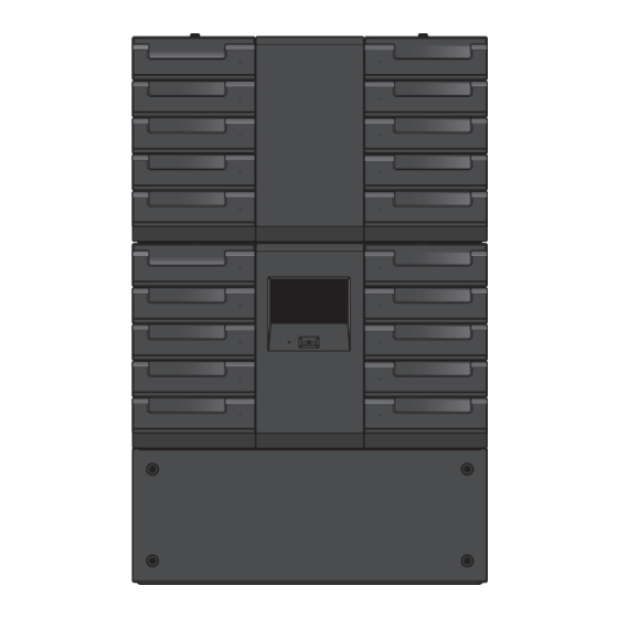
Page 8: Component Names
Introduction Component names Base Module (LB-DH80)_Front panel Pressing the button causes the unit to be turned on and its LED illuminates in green. To turn off the unit, push the button and then select “YES” on the selection menu of the control panel. - Page 9 Introduction Component names The unit has five magazine drawers on both sides capable of storing up to 76 magazines. ≥ Normally, magazine drawers are locked. To open a magazine Magazine drawer drawer, unlock it from the control panel or Web interface. For more information, refer to “Handling a magazine and magazine drawer”...
- Page 10 Introduction Component names Base Module_Rear panel Provides a +24 V DC power supply. Power connector ≥ Before disconnecting a power cable, confirm that LED 5 (POWER) listed in the following field H is off. Serves as ports for a connection to the Bottom Module, Control Control interface port Unit, and the Writer Unit via the supplied exclusive use connection...
- Page 11 Introduction Component names Indicates the operating state of the unit. (The LEDs are numbered from left to right.) ` LED1 (CONTROLLER)/LED2 (CHANGER)/LED3 (DRIVE) Running: illuminates in green Stopped: off ` LED 4 (INFORMATION) LED illuminates in red in a situation that demands the confirmation of the control panel.
- Page 12 Introduction Component names Base Module_Side panel Right-side view Front Left-side view Front Serves for air ventilation of the unit. Ventilation hole ≥ Care should be taken not to block the hole. Serves as a port for data transfer. One of the following interface connector types is installed.
- Page 13 Introduction Component names Bottom Module (LB-DH81)_Rear panel Power connector Provides a +24 V DC power supply. Serves as ports for a connection to the Base Module via the Control interface port supplied exclusive use connection cable. Nameplate Describes a product number, ratings, serial number, etc.
- Page 14 Introduction Component names Control Unit (LB-XC82)_Rear panel Serves as ports for a connection to the Base Module via the supplied Control interface port exclusive use connection cable. Nameplate Describes a product number, serial number, etc. Use this part to remove the Control unit from the Extension Unit. Handle ≥...
- Page 15 Introduction Component names Nameplate Describes a product number, ratings, serial number, etc. Serves as a hole for air ventilation of the unit. Ventilation hole ≥ Care should be taken not to block the hole. Indicates the operating state of the unit. (The LEDs are numbered from left to right.) ` LED1 (CONTROLLER)/LED3 (DRIVE) Running: illuminates in green...
- Page 16 Introduction Component names Extension Unit equipped with a Control Unit/Writer Unit_Side panel Right-side view Front Left-side view Front Nameplate Describes a product number, serial number, etc. Serves as a hole for air ventilation of the unit. Ventilation hole ≥...
-
Page 17: Handling A Magazine And Magazine Drawer
Introduction Handling a magazine and magazine drawer Magazine Use a dedicated magazine for the unit. ≥ For more information about the magazines that can be used, please contact your vendor. ≥ Each magazine has a capacity of 1.2 TB (unformatted/RAID 0) and a data storage life of 50 years (at 30 oC (86 oF) in a 70 % environment)*. - Page 18 Introduction Handling a magazine and magazine drawer User label The following labels can be attached to a user label area of a magazine. ` 1D or 2D code label (only one of them) ` Label with a character string (for magazine management) The 1D/2D code label and the character string label can be used separately or together.
- Page 19 Introduction Handling a magazine and magazine drawer Note ≥ No system operation is affected by the absence of a user label. ≥ A user label shall be attached with no wrinkles and air bubbles. ≥ A glossy user label surface may be difficult to read. ≥...
-
Page 20: How The Unit Identifies A Magazine
Introduction Handling a magazine and magazine drawer How the unit identifies a magazine The unit uses an RFID tag for magazine identification and management. The unit can scans and uses a 1D/2D code label for magazine identification and management. When an RFID tag is damaged and the magazine cannot be identified by the unit, the 1D/2D code label can be used for magazine identification by the unit. -
Page 21: Magazine Drawer
Introduction Handling a magazine and magazine drawer Magazine drawer The Base Module (LB-DH80) and the Extension unit (LB-XH82) each can be equipped with five magazine drawers (10 drawers in total) on both sides. ≥ The order of the middle three drawers is exchangeable on each side. ≥... - Page 22 Introduction Handling a magazine and magazine drawer Each magazine drawer can store up to eight magazines (six magazines only in the bottom drawer). ≥ A magazine number, consisting of the magazine drawer number and any of a number between 1 and 8, is assigned to each magazine.
-
Page 23: Removing A Magazine From A Magazine Drawer
Introduction Handling a magazine and magazine drawer Removing a magazine from a magazine drawer Unlock the magazine drawer. ≥ The unit locks a magazine drawer to prevent it from being opened by mistake. To remove a magazine, unlock the magazine drawer through the control panel or Web interface as follows. ` Control panel: “Manage”... - Page 24 Introduction Handling a magazine and magazine drawer ≥ Before drawing out the magazine drawer, make sure to unlock it. Drawing out the magazine drawer by force may cause damage to it. ≥ Do not draw out the magazine drawer too hard. ≥...
-
Page 25: Mounting A Magazine On A Magazine Drawer
Introduction Handling a magazine and magazine drawer Mounting a magazine on a magazine drawer Preparation ≥ Attach a user label onto a magazine. ( 17) ≥ Confirm that the write disable switch of the magazine is in position. ( 17) Mount a magazine on a magazine drawer. - Page 26 Introduction Handling a magazine and magazine drawer ≥ Do not carry a magazine drawer with its mounting surface down. Failure to observe this instruction may cause the magazine to drop. ≥ Do not touch any mechanical portion other than portions indicated in the instructions of the procedure. Failure to observe this instruction may cause the content of the magazine to fall out.
-
Page 27: Operations
Operations Operation method Set the following items as required. Operations for setting and maintaining the unit The following two methods can be used to set and maintain the unit. ` Operating the control panel on the front of the unit ( 28) Operate the control panel to check the states of the unit, make various network settings, make various settings for opening and closing the magazine drawer, and operate the magazine drawer. -
Page 28: Operating The Control Panel
Operations Operating the control panel Login onto the control panel ≥ When using the “Monitor”, “Config”, and “Manage” menus on the control panel, input a password for login. ≥ When using the unit for the first time after installation, log in onto the control panel and change a password. ≥... - Page 29 Operations Operating the control panel Setup screen Menu button Touch here to return to the displayed menu. Return button Touch here to return to the previous screen. Touch “ ” or “ ” to scroll the screen. Scroll button ≥...
- Page 30 Operations Operating the control panel Menu screen Button for returning to Indicates the previous setup item. previous menu Module selection screen Module name Indicates the module names. Touch here to close the pop-up window and return to the Cancel button previous menu.
-
Page 31: Inputting Numeric And Alphabetic Characters
Operations Operating the control panel Inputting numeric and alphabetic characters To allow for input of numeric or alphabetic characters, a software keyboard is displayed. The software keyboard is changed according to input contents. Use the software keyboard to input numeric or alphabetic characters. Inputting of alphanumeric characters Lower-case character input screen ... - Page 32 Operations Operating the control panel Input character field Indicates an input character. Moves an input position left by one character. Moves an input position right by one character. Clear: Erases one character just before an input position. Pressing and holding this button erases all Operation buttons characters.
-
Page 33: Basic Screen Configuration
Operations Operating the control panel Basic screen configuration Menu Status bar display The current status and time (A to E) of the system are displayed at the top of the screen. Indicates a password locked state. ` “Status”... - Page 34 Operations Operating the control panel Menu display Indicates menu or information. Touch here for operation.
-
Page 35: Panel Menu System
Operations Operating the control panel Panel menu system For more information, refer to a corresponding menu page. ≥ Items with no initial setting listed on the corresponding menu page are set to either null or 0. Menu item Description Page Status Indicates the state of the unit or the like. - Page 36 Operations Operating the control panel Menu item Description Page Allows you to manage the unit. P 67 Open Drawer Unlocks a magazine drawer. P 67 Diagnostic Performs a self-diagnosis. P 67 Enable Password Lock Locks the unit with a password. P 67 Manage Perform Inventory...
-
Page 37: Status Menu
Operations Operating the control panel Status menu This menu allows you to check the operating states of the unit. Indicates both the status of the changer and the drive. Ready: Both status indications are normal. System Status Not Ready: Starting up or performing a self-diagnosis. Not Usable: The system cannot be used because there is an anomaly with either or both the Changer and the Drive Indicates changer status. -
Page 38: Monitor Menu
Operations Operating the control panel Monitor menu This menu allows you to check detailed information and the settings concerning the unit. System <Monitor> Indicates system information concerning the unit. Vendor Name Indicates a vendor name of the unit. Product Name Indicates a part number of the unit. - Page 39 Operations Operating the control panel Changer <Monitor> Indicates information concerning the changer unit of the unit. Indicates the status of the changer unit in the unit. Ready: Normal. Status Not Ready: Starting up or performing a self-diagnosis. Not Usable: Not available due to trouble. Indicates additional information of “Status”...
- Page 40 Operations Operating the control panel Drive <Monitor> Indicates information concerning the drive system of the unit. ≥ Select a module. ( 30) (To display the module selection screen again, select A.) Indicates the state of the drive system of the unit. Ready: Normal.
- Page 41 Operations Operating the control panel The verify mode setting status for writing is displayed. Auto Verify: Automatically determines the records to be verified and then verifies Verify Mode them. All Verify: Verifies all records. ≥ For details, refer to “Verify mode” ( 102). Indicates the number of a magazine currently mounted in the drive system.
- Page 42 Operations Operating the control panel Magazine <Monitor> Indicates information concerning the magazine stored in the unit. ≥ Select a module. ( 30) (To display the module selection screen again, select A.) Select a magazine drawer. ≥ When the selection is made, the magazine drawer list screen is displayed. ...
- Page 43 Operations Operating the control panel Invalid RFIDs are indicated as “Unknown” or by a blank. The information will be indicated correctly when discs are inserted correctly to the drive system. ≥ If 1D/2D code contains a code which cannot be converted to Shift JIS, the code will not be displayed. Magazine detailed information Magazine ID Indicates magazine ID information.
- Page 44 Operations Operating the control panel Network <Monitor> Indicates the network settings. ≥ To change the settings, select “Config” “Network” in order.
- Page 45 Operations Operating the control panel “LAN1”, “LAN2” Indicates the common settings for the protocol stack. Indicates IP stack information. IP Stack ≥ “Unknown” indicates that no setting has been selected. Common (Neither IPv4 nor IPv6 are available.) MAC Address Indicates the MAC address. Speed Indicates the LAN link speed.
- Page 46 Operations Operating the control panel “DNS” DNS Primary Indicates the primary DNS address. DNS Secondary Indicates the secondary DNS address. DNS Tertiary Indicates the tertiary DNS address. * The setting is indicated when “DNS Auto” ( 61) has been set to “Off”.
- Page 47 Operations Operating the control panel Interface <Monitor> Allows you to check settings made for the SAS, iSCSI, and FC interface ports. ≥ Select a module. ( 30) ≥ Indicates settings made for the interface port mounted in the unit. ≥ To change the setting, make the selection in the following order: “Config”...
- Page 48 Operations Operating the control panel For iSCSI interface model “iSCSI Info” Port Indicates an iSCSI port. Indicates the node name. CHAP Indicates information concerning the CHAP authentication. Indicates the target name. Target Name ≥ The target name is indicated only when “CHAP” has been set to “Target Only” or “Target + Initiator”.
- Page 49 Operations Operating the control panel “iSCSI” Indicates the common settings for the protocol stack. Indicates IP stack information. IP Stack ≥ “Unknown” indicates that no setting has been selected. Common (Neither IPv4 nor IPv6 are available.) MAC Address Indicates the MAC address. Speed Indicates the LAN link speed.
- Page 50 Operations Operating the control panel For FC interface model Indicates the setting for the connection speed. Speed ≥ The unit is [bps]. WWPN Indicates the port name. WWNN Indicates the node name. Topology Indicates the topology. FC-AL Loop ID Indicates the loop ID.
- Page 51 Operations Operating the control panel S.M.A.R.T. <Monitor> Indicates a replacement recommended component or a replacement mandatory component, if any. Good: Normal. Warning: Useful life is about to expire. Replacement is recommended. Critical: Operation is no longer possible due to malfunction or other causes. Replacement is mandatory. Flash Memory Indicates information for the flash memory in the unit.
- Page 52 Operations Operating the control panel Error Info <Monitor> Indicates the history of the last five errors or warnings that occurred in the unit from the most recent. Displayed error number/Total number of errors Date and time when error or warning occurred Date Shown as (YYYY/MM/DD HH: MM: SS) Module number where error or warning occurred.
- Page 53 Operations Operating the control panel Config menu This menu allows you to select the desired menu item and make various settings. System <Config> Sets basic information concerning the unit. ≥ Selecting “Save” or “Set” will execute the operation. Sets the unit system name. ≥...
- Page 54 Operations Operating the control panel These settings are for unit date and time. ≥ The settings are used for the date display on the control panel or the Web interface, in the event of an error or warning, and for recording internal logging dates or magazine detail information.
- Page 55 Operations Operating the control panel Specify the read mode for 1D/2D code. CODE39 Only: Read CODE 39 of 1D code only. QR CODE Only: Read QR CODE of 2D code only. Barcode Scan Mode CODE39 + QR CODE: Both CODE 39 of 1D code and QR CODE of 2D code can be read.
- Page 56 Operations Operating the control panel Set RAID Level <Config> Sets an RAID level. ≥ Selecting “Set” will execute the operation. Sets the RAID level. ( 103) RAID 0: Sets RAID 0 level. Select Default RAID RAID 5: Sets RAID 5 level. Level RAID 6: Sets RAID 6 level.
- Page 57 Operations Operating the control panel Email Notice <Config> Makes settings for email notification. ≥ SMTP is used for email notification. Note that no email receiving function is available. ≥ Selecting “Save” will execute the operation. ≥ Selecting “Test” at the bottom of a screen will execute the operation. Selects the use or non-use of an email notification at error occurrence.
- Page 58 Operations Operating the control panel SNMP <Config> Sets SNMP. Three targets can be set as SNMP trap destinations. ≥ Selecting “Save” will execute the operation. Selects the use or non-use of SNMP. On: Enables an SNMP function. Enabled Off: Disables an SNMP function. ≥...
- Page 59 Operations Operating the control panel Network <Config> Makes network settings. ≥ Selecting “Save” or “Set” will execute the operation. “LAN1”, “LAN2” Makes common settings for a protocol stack. Sets an IP stack to be used. IPv4: Communication takes place based on IPv4. IPv6: Communication takes place based on IPv6.
- Page 60 Operations Operating the control panel Makes settings for IPv4. ≥ The settings can be made when “IP Stack” has been set to “IPv4” or “IPv4+6”. Sets DHCP. On: Enables DHCP. DHCP Off: Disables DHCP. ≥ The initial setting is “Off”. IPv4 Sets an IPv4 address.
- Page 61 Operations Operating the control panel “DNS” Sets DNS automatically. ≥ This item is available when “DHCP” of the IP stack to be used has been “On”. DNS Auto On: Enables the setting. Off: Disables the setting. ≥ The initial setting is “Off”. DNS Primary* 1, 2 Sets a primary DNS address.
- Page 62 Operations Operating the control panel Interface <Config> For an iSCSI interface model, set the iSCSI interface port. (For SAS and FC interface models, no settings are required.) ≥ Select a module. ( 30) ≥ Selecting “Save” or “Set” will execute the operation.
- Page 63 ≥ Input a decimal number from 0 to 65536. ≥ The initial setting is “3260”. Sets the node name. ≥ A maximum of 223 characters can be input. ≥ The initial setting is “iqn.1996-03.jp.co.panasonic.da”. Sets up CHAP authentication. Off: Disables CHAP authentication. Target Only: Performs one-way CHAP authentication.
- Page 64 Operations Operating the control panel “iSCSI” Makes the common settings for the protocol stack. Sets an IP stack to be used. IPv4: Communication takes place based on IPv4. IPv6: Communication takes place based on IPv6. IP Stack IPv4+6: Communication takes place based on IPv4 and IPv6.
- Page 65 Operations Operating the control panel Makes the settings for IPv6. ≥ The settings can be made only when “IP Stack” has been set to “IPv6” or “IPv4+6”. Sets a stateless auto configuration. On: Enables a stateless auto configuration. Stateless Auto Config Off: Disables a stateless auto configuration.
- Page 66 Operations Operating the control panel Contrast <Config> Sets a contrast on the control panel. ≥ Selects a desired level from eight levels 1 to 8. The higher the level is, the brighter the control panel will be. ≥ The initial setting is “4”. ≥...
- Page 67 Operations Operating the control panel Manage menu This menu allows you to manipulate the unit. Unlocks a magazine drawer. ≥ Select module and magazine drawer. Read a message before performing an operation. ( 30) ≥ Once a magazine drawer has been unlocked, it protrudes slightly. Open Drawer ≥...
- Page 68 Operations Operating the control panel Updates the unit software. ( 108) When updating this software, write update file to a USB memory and connect the Update Software USB memory to a USB port on the rear of the unit prior to this update operation. ≥...
-
Page 69: Service Menu
Operations Operating the control panel Service menu This menu is intended for the unit maintenance or the like. This menu cannot be operated because of password protection for exclusive use by your support service provider. -
Page 70: Web Interface Operation
Operations Web interface operation Access to Web interface Start a Web browser and input the unit’s IP address in the address field. IPv4: http://0.0.0.0 (0.0.0.0 is the unit IP address) IPv6: http://[0:0:0:0:0:0:0:0] (0:0:0:0:0:0:0:0 is the unit IP address) ≥ When using DHCP, check the IP address of the unit assigned by DHCP. ( 45) ≥... -
Page 71: Web Interface Screen
Operations Web interface operation Web interface screen The following shows the basic configuration of the Web interface screen and its display contents. Logout Logout Button When selecting a menu item (Monitor/Configure/Manage/Service), the Menu submenus of each item are displayed. ≥... -
Page 72: Web Interface Menu System
Operations Web interface operation Web interface menu system For more information, refer to a corresponding menu page. ≥ Items with no initial setting listed on the corresponding menu page are set to either null or 0. Menu item Description Page Indicates the detailed information or settings of the unit. - Page 73 Operations Web interface operation Menu item Description Page Allows you to manage the unit. P 97 Open Drawer Requests magazine drawer unlock. P 97 Perform Inventory Reacquires magazine information. P 97 Manage Shutdown Shuts down and reboots the unit. P 98 Update Software Updates the unit software.
- Page 74 Operations Web interface operation Monitor menu This menu allows you to check detailed information and the settings concerning the unit. System <Monitor> Indicates system information concerning the unit. Vendor Name Indicates a vendor name of the unit. Product Name Indicates a product number of the unit. Software Version Indicates a version of software incorporated into the unit.
- Page 75 Operations Web interface operation Changer <Monitor> Indicates information concerning the changer unit of the unit. Indicates the status of the changer unit in the unit. Ready: Normal. Status Not Ready: Starting up or performing a self-diagnosis. Not Usable: Not available due to trouble. Indicates additional information of “Status”.
- Page 76 Operations Web interface operation Drive <Monitor> Indicates information concerning the drive system of the unit. Indicates the state of the drive system of the unit. Ready: Normal. Status Not Ready: Starting up or performing a self-diagnosis. Not Usable: Not available due to trouble. Indicates additional information of “Status”...
- Page 77 Operations Web interface operation Indicates the number of a magazine currently mounted in the drive system. e.g., A L1 5 Slot number Magazine Address Magazine drawer number R: right magazine drawer L: left magazine drawer Module name Magazine Barcode Indicates the 1D/2D code of a magazine currently mounted in the drive system.
- Page 78 Operations Web interface operation Magazine <Monitor> Display each magazine’s information. ≥ Select a magazine. ≥ The information displayed for each magazine indicates the following status: Vacant: Magazine not present Occupied: Magazine present Mounting: Magazine currently used in the drive system Shelter: Dead storage Disable: Unusable Unknown: Unknown...
- Page 79 Operations Web interface operation Network <Monitor> Indicates the network settings. ≥ To change the setting, make the selection in the following order: “Configure” “Network” ( 90) “DNS” DNS Primary Indicates the primary DNS address. DNS Secondary Indicates the secondary DNS address. DNS Tertiary Indicates the tertiary DNS address.
- Page 80 Operations Web interface operation “LAN1”, “LAN2” Indicates the common settings for the protocol stack. Indicates IP stack information. IP Stack ≥ “Unknown” indicates that no setting has been selected. Common (Neither IPv4 nor IPv6 are available.) MAC Address Indicates the MAC address. Speed Indicates the LAN link speed.
- Page 81 Operations Web interface operation Interface <Monitor> Indicates the settings of the interface port of each module. “SAS” Indicates the connection speed settings. Speed ≥ The unit is [bps]. SAS Address Indicates the WWID (World Wide Identifier). “iSCSI” ≥ To change the setting, make the selection in the following order: “Configure”...
- Page 82 Operations Web interface operation Indicates IP stack information. IP Stack ≥ “Unknown” indicates that no setting has been selected. (Neither IPv4 nor IPv6 are available.) MAC Address Indicates the MAC address. Speed Indicates the LAN link speed. Indicates the settings for IPv4. ≥...
- Page 83 Operations Web interface operation “FC” Indicates the setting for the connection speed. Speed ≥ The unit is [bps]. WWPN Indicates the port name. WWNN Indicates the node name. Topology Indicates the topology. Indicates the loop ID. FC-AL Loop ID ≥ The loop ID is indicated only when “Topology” has been set to “FC-AL”.
- Page 84 Operations Web interface operation View Logs <Monitor> Indicates the various logs of the unit. ≥ Select or enter the item and then select the “View” button to view. Selects the log type to be displayed. Standard Trace: View the information history. Log Type Warning Trace: View the warning history.
- Page 85 Operations Web interface operation Serial Number <Monitor> Indicates the serial number of each module. Drawer <Monitor> Indicates the unlocking/locking status of magazine drawers.
-
Page 86: Configure Menu
Operations Web interface operation Configure menu This menu allows you to select the desired menu item and make various settings. System <Configure> Sets basic information concerning the unit. ≥ Change the settings, then select “Submit” to accept the change. Sets the unit’s system name. ≥... - Page 87 Operations Web interface operation Date/Time <Configure> Sets the date and time of the unit. ≥ The settings are used for the date display on the control panel or the Web interface, in the event of an error or warning, and for recording the internal logging date or magazine detail information. ≥...
- Page 88 Operations Web interface operation Date/Time Format <Configure> Sets the time and date display format. ≥ Change the settings, then select “Submit” to accept the change. Sets the 12-hour or 24-hour system for the time display. 12h: Uses a 12-hour system for time display. 12h/24h 24h: Uses a 24-hour system for time display.
- Page 89 Operations Web interface operation Support Contact <Configure> Set your support service provider contact information. ≥ Change the settings, then select “Submit” to accept the change. Sets your support service provider name. Support Name ≥ A maximum of 64 alphameric characters can be input. Sets the phone number of your support service provider.
- Page 90 Operations Web interface operation Network <Configure> Makes network settings. ≥ Change the settings, then select “Submit” to accept the change. “SSL” Sets the Web Interface access using SSL. Check (enable): Use SSL. To access the Web interface, enter “https://(IP address)”. Enable SSL For Web Uncheck (disable): SSL is not used.
- Page 91 Operations Web interface operation “LAN1”, “LAN2” Sets an IP stack to be used. IPv4: Communication takes place based on IPv4. IP Stack IPv6: Communication takes place based on IPv6. IPv4+6: Communication takes place based on IPv4 and IPv6. ≥ The initial setting is “Unknown”. (Communication based on IPv4 or IPv6 is not possible) Sets a LAN link speed.
- Page 92 ≥ Input a decimal number from 0 to 65536. ≥ The initial setting is “3260”. Sets the node name. ≥ A maximum of 223 characters can be input. ≥ The initial setting is “iqn.1996-03.jp.co.panasonic.da”. Sets up CHAP authentication. Off: Disables CHAP authentication. Target: Performs one-way CHAP authentication.
- Page 93 Operations Web interface operation Sets an IP stack to be used. IPv4: Communication takes place based on IPv4. IP Stack IPv6: Communication takes place based on IPv6. IPv4+6: Communication takes place based on IPv4 and IPv6. ≥ The initial setting is “Unknown”. (Communication based on IPv4 or IPv6 is not possible) Sets a LAN link speed.
- Page 94 Operations Web interface operation Set RAID Level <Configure> Sets the RAID level. Sets the RAID level. ( 103) ≥ Change the settings, then select “Submit” to accept the change. RAID 0: Sets RAID 0 level. Default RAID Level RAID 5: Sets RAID 5 level. RAID 6: Sets RAID 6 level.
- Page 95 Operations Web interface operation Email Notification <Configure> Makes settings for email notification. ≥ SMTP is used for email notification. Note that no email receiving function is available. ≥ Change the settings, then select “Submit” to accept the change. Selects the use or non-use of an email notification at error occurrence. Notify Errors ≥...
- Page 96 Operations Web interface operation SNMP <Configure> Sets SNMP. Three targets can be set as SNMP trap destinations. ≥ Change the settings, then select “Submit” to accept the change. Selects the use or non-use of SNMP. Enabled ≥ This function is disabled in the initial setting. Target 1 - IP Address Sets the IP address and the SNMP Version of Target 1/2/3.
- Page 97 Operations Web interface operation Manage menu This menu allows you to manipulate the unit. Open Drawer <Manage> Requests magazine drawer unlock. ≥ After sending the unlock request, the magazine drawer can be unlocked on the control panel. ( 67) Request Sends the request to unlock the selected magazine drawer to the control panel.
- Page 98 Operations Web interface operation Shutdown <Manage> Shuts down and restarts the unit. Shuts down the unit. ≥ Terminate the application prior to this operation. Shutdown ≥ The unit has a Wake-on-LAN capability. After this shutdown operation, the unit can be started quickly through the use of an LAN port. Restarts the unit.
- Page 99 Operations Web interface operation Save Log Dump <Manage> Download the log of the unit. ≥ Select “Save” to save the settings. Download log files for the user. User Log File ≥ For more information about log files, refer to “Log functions” ( 110). Download the log files for your support service provider.
- Page 100 Operations Web interface operation Service menu This menu is intended for the unit maintenance or the like. This menu cannot be operated because of password protection for exclusive use by your support service provider.
-
Page 101: Various Functions
Operations Various Functions Wake-on-LAN function/Turn off function via LAN port ∫ Turn on power To turn on the unit power, press the power button or connect the LAN port to the LAN and use the Wake-on-LAN function. ≥ Some applications do not support the Wake-on-LAN function. For more information, refer to the application manual. -
Page 102: Encryption Of Write Content
Operations Various Functions Encryption of write content This unit enables the encryption of the write/read contents. The data encryption can be used corresponding to Advanced Encryption Standard (AES) with a key length of 256 bits. The encryption key is available from the application. For more information, refer to the user manual for the application. -
Page 103: Raid Functions
Operations Various Functions RAID functions The unit provides RAID functions for the purpose of improving the reliability and availability. The fault tolerance for the protection of data is different when writing and reading. RAID levels for each write and read are listed in the following table. ≥... - Page 104 Operations Various Functions How to set/cancel RAID level Set the RAID level for each magazine when formatting it so that the unit can perform write/read to the magazine based on the RAID level. ≥ You can specify the RAID level to format magazine on the unit or application. To specify the RAID level with the unit, select “Config”/“Configure”...
-
Page 105: S.m.a.r.t. Information
Operations Various Functions S.M.A.R.T. information The unit provides a function that diagnoses the lifetime based on the amount of use of built-in units or the characteristic values. The unit diagnoses the built-in fan in the system, controller storage device, changer unit, drive system, and magazines, then generates a warning if these are approaching the end of lifetime. -
Page 106: Email Notification
Operations Various Functions Email notification The details of the error or warning will be sent by email according to the email notification settings. The error or warning code is included in the subject and message of the email. ≥ In order to send a test email to the address set in “To Email Address” ( 57, 95) following the steps below. ` Control panel: “Config”... -
Page 107: Snmp
Operations Various Functions SNMP The unit provides SNMP agent feature to manage the unit by remote monitoring. The feature supports SNMP version 1 and 2c. This enables you to acquire the information about the unit from the SNMP manager and to send the information from the unit to SNMP manager (SNMP Trap notification). ≥... -
Page 108: Software Update
Operations Various Functions Software update To update the unit software, select “Manage” “Update Software” on the control panel or Web interface. If you wish to update on the control panel, a USB memory is required. ( 68) ≥ For information on how to obtain the update file, contact the vendor. ≥... -
Page 109: Diagnostic
Operations Various Functions Diagnostic The unit provides a self-diagnostic function. The self-diagnostic function operates at predetermined times on the built-in changer unit, drive system, flash memory on the controller, fans, control panel, internal host interface and external power supply, respectively. You can also execute the self-diagnostic function by selecting “Manage”... -
Page 110: Log Functions
Operations Various Functions Log functions The unit provides a log function to check the history of errors or warnings. ≥ To obtain the log, select “Manage” “Save Log Dump” on the control panel or Web interface. ( 68, 99) ≥... - Page 111 Various Functions Examples of the logs Date/Time : 2015/01/01 13:00:00 (YMD) ----------------------------------------- Device Information: ------------------- Vendor Name : Panasonic Product Name : LB-DH8 Software Version : GN0.0.00 Serial Number B : DA2ESPR-A15 A : DA2ESPR-015 M : MES20015 System Name...
-
Page 112: Magazine Eject Mode
Operations Various Functions Magazine eject mode The magazine eject mode is an auxiliary function will eject a magazine which has been specified by the application. ≥ After ejecting the specified magazine, return to the normal panel screen. Select the module to eject the magazine. The control panel display will change to the following when the magazine eject mode is specified by the application. - Page 113 Operations Various Functions Select the magazines to be ejected. Back to the normal control panel. ≥ Select the button after ejecting all of the specified magazines from the magazine drawer or when exiting the magazine eject mode. ≥...
-
Page 114: Troubleshooting Guide
Others Troubleshooting guide Connection or installation problems Item Problem Cause/Solutions ± Installation problems Unlock the magazine drawer “Processing” is displayed and it The changer mechanism in the unit is takes a long time to unlock. operating. )Please wait. When unlocking the magazine drawer on the control panel or the Web interface, an error is displayed and the drawer cannot be unlocked. - Page 115 Others Troubleshooting guide Item Problem Cause/Solutions ± Installation problems Communication between One of “E1060”, “E1070”, “E2030”, The Communication between modules or modules or devices “E2032”, “E2033”, “E2034” is devices may not be working properly. )Check whether cables are correctly displayed, and the control panel connected to the unit.
- Page 116 Others Troubleshooting guide Item Problem Cause/Solutions ± Host interface problems )Check the transfer rate. ( 7) Transfer rate The transfer rate of the SAS If the transfer rate is slow, make sure interface is slow. the cable/interface adaptor/server supports the transfer rate, and ensure the connection is made.
-
Page 117: Operating Problems
Others Troubleshooting guide Operating problems Item Problem Cause/Solutions ± Power supply problems Cannot turn on the power LED 5 (POWER) on the back )Check DC is output from an external power supply. Refer to the user panel is off. manual for the external power supply. When the power is on, LED 5 )Check if the DC cable which connects (POWER) on the back panel is... - Page 118 Others Troubleshooting guide Item Problem Cause/Solutions Cannot turn off in the “Eject The application sets the magazine eject Medium Mode” screen. mode. )Execute or terminate the ejection of (Warning code: W2150) magazine on the control panel, and try again. “Update Software” or Software is updating.
- Page 119 Others Troubleshooting guide Item Problem Cause/Solutions ± Information LED problems )Turn off and on the unit. Information LED Does not illuminate when an error If the problem persists, please contact is displayed on the control panel. your support service provider. ( 138) ±...
- Page 120 Others Troubleshooting guide Item Problem Cause/Solutions ± Read/write problems )Check if an error has occurred. Reading magazine Does not read the recognized If an error has occurred, check the magazine. error code and try the solutions. ( 130) )The new magazine is not formatted. Refer to the user manual for the application and execute format.
- Page 121 Others Troubleshooting guide Item Problem Cause/Solutions ± RAID problems )Check the level on the control panel or Don’t know the RAID level Don’t know the current RAID level the Web interface. ( 40, 76) for the unit. (Settings include those of the unit, the Don’t know the current RAID level application, and the magazine.) for the magazine.
- Page 122 Others Troubleshooting guide Item Problem Cause/Solutions ± Software problems )Consult the vendor. Updating Don’t know how to obtain an update file. Cannot update (error message) “W2120” is displayed. The application prohibits the ejection of the media from the drive system. )Permit ejection from the application and try again.
- Page 123 Others Troubleshooting guide Item Problem Cause/Solutions Cannot update from the Web )Obtain the update file again. )When upload has failed on the Web interface. browser, see “Web interface” ( 124) )Update from the control panel. )Press the power button for at least After updating Does not start up after the software 15 seconds to force the unit to turn off,...
- Page 124 Others Troubleshooting guide Item Problem Cause/Solutions Web interface Cannot access the Web interface. )Refer to “Network” ( 125). )When DHCP is used, check if the IP address has been acquired and it has not been updated. )Check that HTTP is not blocked by the network settings.
- Page 125 Others Troubleshooting guide Item Problem Cause/Solutions Network Cannot communicate. (LNK/ACT )Check the network cable and the connectivity. LED of LAN port is off) )Connect to another LAN port on the unit. )Connect to another port on the network device. Cannot communicate. (LNK/ACT )Check the network configuration parameters.
- Page 126 Others Troubleshooting guide Item Problem Cause/Solutions SNMP Trap notification is not delivered. )Refer to “Network” ( 125). )Check the trap notification destination address. )Verify the SNMP settings “Community Name” and “Target 1 IP Address/ Target 2 IP Address/Target 3 IP Address”.
-
Page 127: Errors And Warnings
Others Errors and warnings If an error or warning situation arises during operation of the unit, the information LED illuminates in red on the front of the unit, a pop-up message is displayed on the control panel, and then logging takes place. In addition, an email or SNMP trap notification is issued in response to the contents of the error or warning so long as a setting for email notification or SNMP trap notification is made. - Page 128 Others Errors and warnings ∫ How to check errors and warnings [Control panel] When an error or a warning occurs, the error or warning code and message is displayed in the pop-up screen on the control panel. Acknowledge the code and message and select “ ”...
- Page 129 Others Errors and warnings [Email notification] When an error or a warning occurs, the details of the error or warning will be sent by email according to the email notification settings. ≥ For more information, refer to “Email notification” ( 106). [SNMP Trap] The details of the error or warning will be sent by SNMP trap according to the SNMP settings.
-
Page 130: List Of Error Codes
Others Errors and warnings List of error codes Email SNMP trap Code Action to be taken notification notification E1000 A fault has been detected in flash memory in the unit or the ± ± peripheral circuit. It needs to be repaired. E1010 The internal temperature of the unit is high. - Page 131 Others Errors and warnings Email SNMP trap Code Action to be taken notification notification E2020 The changer mechanism in the changer unit or the drive in the drive system has failed to operate. E2021 )Withdraw the magazine drawer to make sure the installation of ±...
-
Page 132: List Of Warning Codes
Others Errors and warnings Email SNMP trap Code Action to be taken notification notification E3031 Failed recording due to multiple factors of the drive system and a magazine. Recording to the magazine is disabled. ± ± )Check if any problems with the drive system and the magazine have been detected in the log. - Page 133 Others Errors and warnings Email SNMP trap Code Action to be taken notification notification W1040 Detected that the life of the memory on the controller is nearly at its ± ± end. )We recommend to replace the controller. W1041 Detected that the life of the flash memory on the controller is nearly ±...
- Page 134 Others Errors and warnings Email SNMP trap Code Action to be taken notification notification W1082 The password you entered does not meet the password rules. )Include alphabets in the password. W1083 The password you entered does not meet the password rules. )Include symbols in the password.
- Page 135 Others Errors and warnings Email SNMP trap Code Action to be taken notification notification W1122 The command cannot be executed because a magazine is loaded in the drive system. )Use an application to remove the magazine from the drive system. W2000 Performance of the changer mechanism operation in the changer unit has deteriorated.
- Page 136 Others Errors and warnings Email SNMP trap Code Action to be taken notification notification W2140 The changer unit is operating. )Check the changer status by control panel or Web interface and retry processing after the status changes to “Ready”. W2150 The specified processing cannot be performed because of the magazine eject mode set for taking out a disc specified by an application.
-
Page 137: Appendix
Others Appendix Countermeasures against static electricity To prevent the unit from being damaged by static electricity, observe the following instructions. ≥ For transportation or long-term storage, wrap the unit with an antistatic sheet and store it in a packing box. Do not touch the unit directly by hand as much as possible. -
Page 138: Contacting Your Support Service Provider
≥ Please remove the products that are no longer used to prevent falls in case of an emergency. Disclaimer ≥ Panasonic assumes no responsibility for any data loss and direct or indirect damage caused by the use, malfunction, or any failure of the unit regardless of whether the unit is under warranty or not. -
Page 139: Specifications
Others Specifications LB-DH8 series (common) Maximum transfer rate 216 MB/sec per host interface port (RAID 0)* Compatible magazines Part number: LM-BM12LB 1.2 TB recordable magazine* (writable/readable) Maximum system 46U rack system configration Base Module: 1 unit Bottom Module: 1 unit... -
Page 140: Base Module
Others Specifications Installation requirements Front: 1,400 mm (56z) or more for space (for maintenance) Rear: 1,000 mm (40z) or more for space (for maintenance) Tilt: 3 degrees or lower (Left-right), 2 degrees or lower (Front-back) Base Module Part number LB-DH80A0G (SAS interface model) LB-DH80S0G (iSCSI interface model) LB-DH80F0G (FC interface model) Model number... -
Page 141: Bottom Module
Others Specifications Management interface Transfer rate: 1 Gbps Port: 2 Wake-on-LAN: Supported Connector: RJ45 Applications: Web interface, SNMP, email notification, time server communication USB2.0 Port: 2 Connector: Type A Applications: USB memory connection (FAT16 or FAT32 format), software updates, save/recover settings, log storage, maintenance Port: 1 Connector: RJ45 Applications: Control and monitoring external power supply... -
Page 142: Extension Unit
Others Specifications Dimensions (W): 446 mm (17.6z) (19-inch rack EIA), 482 mm (19.0z) (Including mounting bracket) (H): 171 mm (6.8z), 175 mm (6.9z) (Including the projecting parts) (D): 851 mm (33.6z) (Excluding the projecting parts), 867 mm (34.2z) (Including the projecting parts) Mass (Weight) Approx. -
Page 143: Writer Unit
Others Specifications Writer Unit Part Number None Model Number LB-XD82 Number of Installed 1 drive system (12 drive units) Drive System Laser Wave length: 405 nm Host interface SAS (Serial Attached SCSI) Transfer rate: 6 Gbps Port: 1 Wake-on-LAN: Unsupported Connector: SFF-8088 Mini-SAS iSCSI (Internet Small Computer System Interface) Transfer rate: 10 Gbps... -
Page 144: Extension Module (With The Writer Unit)
Others Specifications Extension Module (with the Writer Unit) Part Number LB-DH82A0G (SAS interface model) LB-DH82S0G (iSCSI interface model) LB-DH82F0G (FC interface model) Configuration Extension Unit LB-XH82 and Writer Unit LB-XD82 * 1: The transfer rate with RAID configuration is RAID 0: 216 MB/sec, RAID 5: 198 MB/sec, RAID 6: 180 MB/sec. * 2: The capacity with unformatted RAID configuration is RAID 0: 1.2 TB, RAID 5: 1.1 TB, RAID 6: 1.0 TB. -
Page 145: About Copyright
“Software Information Display” from the Web interface. At least three (3) years from delivery of this product, Panasonic will give to any third party who contacts us at the contact information provided below, for a charge no more than our cost of physically performing source code distribution, a complete machine-readable copy of the corresponding source code covered under GPL V2.0, LGPL... -
Page 146: Glossary
Others Glossary Changer unit Mounting bracket The changer unit is a robot mechanism to transfer Mounting brackets are used when fixing the Base magazines from the magazine drawer to the drive Module and Bottom Module, Extension Unit to a system. The Bottom Module (LB-DH81) has a single rack. -
Page 147: Index
Others Index S.M.A.R.T......51, 84, 105 Application ....27, 101, 102, 103, 112 Changer unit. - Page 148 Panasonic Corporation Kadoma, Osaka, Japan SQW0319 C Panasonic Corporation 2015 F0215YK0...
Need help?
Do you have a question about the LB-DH8 series and is the answer not in the manual?
Questions and answers