
Related Manuals for GRASS VALLEY CR6400 Family


Summary of Contents for GRASS VALLEY CR6400 Family
- Page 1 CR6400 Family Digital Compact Routers and Control Panels User’s Guide UG0078-01 30 Sep 2014...
- Page 2 Grass Valley. A Grass Valley manual may have been revised to reflect changes made to the product during its manufacturing life. Thus, different versions of a manual may exist for any given product.
-
Page 3: Fcc Statement
Declarations of Conformance on file in the Grass Valley offices in Grass Valley, California USA. Software License Agreement and Warranty Information Contact Grass Valley for details on the software license agreement and product warranty. - Page 4 Grass Valley product electronic components and structural materials to RoHS compliance. It is our objective at Grass Valley to maintain compliance with all relevant environmental and product regulatory requirements. Detailed information on specific products or on the RoHS...
- Page 5 The fuse symbol indicates that the fuse referenced in the text must be replaced with one having the ratings indicated. The presence of this symbol in or on Grass Valley equipment means that it has been designed, tested and certified as complying with applicable Underwriter’s Laboratory (USA) regulations and recommendations.
- Page 6 • To avoid fire hazard, use only the specified fuse(s) with the correct type number, voltage and current ratings as referenced in the appropriate locations in the service instruc- tions or on the equipment. Always refer fuse replacements to qualified service person- nel.
-
Page 7: Table Of Contents
Table of Contents 1 Preface ..........1 Chapter Structure . - Page 8 Table of Contents 4 Configuration ......... 23 Stand-Alone Routers .
- Page 9 CR6400 User’s Guide 6 CRSC Network Operation ......49 Summary ..................49 Terminology .
- Page 10 Table of Contents 7 Maintenance ......... . 75 Prevention .
-
Page 11: Preface
........... . . 2 Chapter Structure The following chapters provide detailed instructions for all aspects of the CR6400 family of compact routers and control panels: •... -
Page 12: Terms, Conventions And Abbreviations
Preface Terms, Conventions and Abbreviations • Use the ‘First Page’ , ‘Previous Page’ , and ‘Next Page’ , and ‘Last Page’ buttons to go to the first, previous, next, or last page within a PDF file. Note To display the navigation buttons, right-click the Tool Bar area, and check ‘Navigation’ . •... -
Page 13: Introduction
Overview Summary The CR6400 family is a unique subset of Grass Valley’s CR series of compact routers: the family’s routers have a larger switching matrix (64×64) and modular construction. The CR6400 routers are 2RU routers, are about 10 inches deep. -
Page 14: Compact Router Background
Introduction Overview The default functions include: Source Mode Destination Mode Source Select Destination Select Panel lock Destination Lock Level 1–Level 4 In the default function set, four of the buttons are unused. When the panel is configured in CRSC (Compact Router System Configurator), all the buttons of the panel are configurable and support salvos, which are not available in the default function set. -
Page 15: Stand-Alone Cr6400 Usage
Automation is left to the customer and is not addressed in this document. Stand-Alone CR6400 Usage The CR6400 family routers can also be used in the following ways: • As a single stand-alone CR6400 router with a “captive” control panel or with automation. -
Page 16: The Router
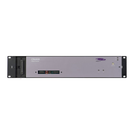
Introduction The Router The Router The CR6400 routers are 2RU routers. They are about 10” deep to accommodate removable I/O cards. This is a front view of the router: Power LEDs (Removable) Fan Unit Fan LED Rotary Switch Connector Cover Plate Reference LED The CR6464-3Gig and the CR6464-AES routers have the same features at the front. -
Page 17: Control Card
Maintain buffer for video timing with respect to the video reference. • Execute switches (with respect to the video reference) and perform locks and unlocks. • Read the rotary switch at startup. • Communicate with an automation or control system • Communicate with other CR6400 family routers over Ethernet. -
Page 18: Ports
Introduction The Router Ports The control card has several ports: Serial Port Ethernet Port Video Reference Serial Port The serial port uses a DE9 connector, and supports RS-422 or RS-485 protocol. This is the pinout of the port: TX– n.c. RX–... -
Page 19: Crosspoint Card
CR6400 User’s Guide Crosspoint Card The crosspoint (XPT) card contains the switching matrix: Alarm LED Power LED There are no connectors on the XPT card, but it does have an alarm LED and a power LED. The power LED is green when the control card has good power and red if power is faulty. The alarm LED is red when an alarm condition exists (such as the absence of a video reference). -
Page 20: The Control Panel
Introduction The Control Panel The Control Panel A thin 2RU control panel — the CP6464 — can mount directly on the front of the router as shown here: Dest. Lock Panel Lock Power LEDs Level (1–4) Unused (4) Selection Buttons (64) Fan LED Dest. -
Page 21: Stand-Alone Definitions
CR6400 User’s Guide • Destination Mode. The destination mode button enables destination selection using the array of selection but- tons. When a panel operator presses the destination selection button, we say the panel is in desti- nation mode. The 64 selection buttons turn amber and permit the selection of one of 64 des- tinations. -
Page 22: Stand-Alone Button Color
Introduction Feature Summary Stand-Alone Button Color A panel’s buttons have color: green, amber, red and are either bright (high-tally), dim (low-tally), or off (disabled). Buttons go high-tally when selected (pressed) and remain low-tally when they are not selected. In general, green means source and amber means destination. These colors have other meanings, however. -
Page 23: Stand-Alone Mode
CR6400 User’s Guide Stand-Alone Mode In stand-alone operation, the CP6464 has the following characteristics: • The meaning of I/O buttons is fixed and the mapping of buttons to I/O connectors is fixed. The set of 64 buttons represents sources when the source mode button is pressed and repre- sents destinations when the destination mode button is pressed. - Page 24 Introduction Feature Summary • Each button has a clear plastic cap that can be easily removed to accommodate customer- defined button legends. • Two LEDs indicate whether the power supplies of the router on which the control panel is mounted are connected and functioning. •...
-
Page 25: Installation
................. . . 20 Package Contents If you have ordered CR6400 routers (and products related to them) from Grass Valley, you should inspect the shipping container for damage. If you find any container damage, unpack and inspect the contents. -
Page 26: Design Considerations
Installation Design Considerations Design Considerations By the time you are ready to install your equipment and software, you (or someone in your orga- nization) will have already made most of the system design decisions. In fact, the design decisions will have been made before the equipment is ordered. The following is a review of the concepts. -
Page 27: Rack Mount
CR6400 User’s Guide Rack Mount The CR6400 routers are designed to mount in a 19” rack. Rack-mounting is not a requirement, but we assume a 19” rack for the sake of simplicity. Follow these steps to install a CR6400 router: 1 Set the position of the 16-position rotary switch on the front of the router. -
Page 28: Creating A Router Network
Installation Creating a Router Network The external power supplies are described in Power Specifications on page 77. Each connec- tor has 4 pins. The enclosing ring of the cable connectors are connected to ground. Be careful not to short the power pins (+48V) to the ring. ... -
Page 29: Stand-Alone Networks
CR6400 User’s Guide Stand-Alone Networks A stand-alone CR6400 network comprises the following items: • From 1 to 4 CR6400 routers. • A CP6464 panel. • An Ethernet switch capable of 100MB/s operation with enough ports to accommodate your routers. Figure 3-1 shows a stand-alone network of CR6400 routers: Ethernet Switch Router 1 Router 2... -
Page 30: Testing
If the router and panel pass all of these simple tests, it is likely to be working properly. You can now proceed with I/O connections and more exhaustive and detailed testing that is dependent only your installation. Report any failures to Grass Valley customer service. -
Page 31: Stand-Alone Network
1. Level button 2 corresponds to the router whose rotary switch was set to 2, and so on. Report and correct any failures before proceeding. Further Testing Perform a few multi-level takes and locks. See Chapter 5, Stand-Alone Operation, for instructions. Report failures to Grass Valley customer service. - Page 32 Installation Testing...
-
Page 33: Configuration
Configuration Chapter 4 provides configuration instructions for the CR6400 routers and the CP6464 panel. Topics Stand-Alone Routers ..............23 Stand-Alone CR6400 Networks . - Page 34 Configuration Stand-Alone Routers The Physical Inputs and Output Connections The 3Gig and AES I/O cards have 32 DIN 1.0/2.3 connectors. (We call them “coax” connectors.) All the inputs are on the left and all the outputs are on the right. The alarm and power LEDs (and the card label) separate the two sections of a card.
-
Page 35: Stand-Alone Cr6400 Networks
CR6400 User’s Guide Stand-Alone CR6400 Networks For each router, set up I/O, video reference, and power and ground connections as you would for stand-alone routers. IP Addresses and Levels A stand-alone network allows up to 4 routers (levels 1–4). Decide what signal types (3Gig, AES, etc.) you want on which levels and set the rotary switch position to configure the levels accord- ingly. -
Page 36: Remote Panel Modes
Configuration CRSC Networks • A source is a set of inputs on one or more routers, on one or more levels. The inputs might, or might not, belong to a single physical device. • A destination is a set of outputs on one or more routers, on one or more levels. The outputs might, or might not, belong to a single physical device. -
Page 37: Salvos
“pages. ” The panels that have “paging” buttons are the CP6464 and CP32-6464. These are the panels that can control networks that include CR6400 family routers. (The CP6401 also controls CR6400 family routers but does not have paging buttons.) Select a paging method. -
Page 38: Panel Types For Cr6400 Routers
Configuration CRSC Networks Panel Types for CR6400 Routers These are the panel types available in CRSC: CP32-6464 CP6401 CP6464 • The CP6464 is a 2RU panel capable of switching 64 sources to 64 destinations. • The CP6401 is a 2RU single-destination panel. In CRSC, it has a single “default destination” button in CRSC, but the actual panel has no destination buttons. -
Page 39: How To Add Remote Panel Modules To A Network
CR6400 User’s Guide How to Add Remote Panel Modules to a Network Follow these steps to add remote panel modules to your network: 1 Connect up to 15 remote panel modules to the network with unique rotary switch settings in the range 1 to F. Remember to cycle power after you change a rotary switch. -
Page 40: How To Add A Level
Configuration CRSC Networks 3 Define the physical start and end numbers for the level. These numbers identify physical connections on the router. The numbers you enter will of course depend on what you want to do with the router. The default level for the router covers the entire span of inputs and outputs. For example, the default values for a 64×64 router are input start = 1, input end = 64, output start = 1, output end = 64. -
Page 41: Configuring A Panel In Crsc
CR6400 User’s Guide If your subnet has more than one router, CR6400 adds a default level for the router you chose in the dialog of step 3. You can now edit the parameters for this level. (See How to Update a Level on page 29.) 5 Repeat steps 2–4 for additional levels. - Page 42 Configuration CRSC Networks Summary’ button at the bottom of the page to bring CRSC and the actual hardware into sync.) Among the various panel types, these are the panel types related to CR6400 routers: CP32-6464 CP6401 CP6464 You will be able to choose CP32-6464 only if a CP3232 is mounted on the remote panel mod- ule (or if no panel is mounted.) You will be able to choose CP6401 or CP6464 only if a CP6464 is mounted on the remote panel module.
- Page 43 CR6400 User’s Guide The ‘Display Page 1’ button causes the panel to present Segments 1 and 3 Functions 1–32 On the top 32 buttons Functions 65–96 On the bottom 32 buttons and the ‘Display Page 2’ button causes the panel to present Segments 2 and 4 Functions 33–64 On the top 32 buttons...
-
Page 44: Defining Destination Buttons
Configuration CRSC Networks The buttons in the graphic image of the configuration page correspond in number and posi- tion to the buttons of the actual control panel. (The CP6401 is an exception: the graphic has a button for the configured destination, but the panel has no such button.) The ‘Destination Lock’... -
Page 45: Defining Level Buttons
CR6400 User’s Guide When entering an output on level C, you specify an output in the range 1–8, not 17–24. Output 3 of level C is router output 19 (in this example). You would specify (level C, output 3) in the table and run cable to the router’s output BNC numbered 19. -
Page 46: Defining Salvo Buttons
Configuration CRSC Networks Defining Salvo Buttons A salvo is a stored sequence of primitive takes. A primitive take routes one router input to one router output, on a designated level (or partition). You can define up to 64 different salvos for a panel and each salvo can execute up to 64 primitive takes, subject to a total of 1024 primitive takes. -
Page 47: Defining Source Buttons
CR6400 User’s Guide Defining Source Buttons To configure a button as a source button: 1 Click on the image of the particular button you want to configure. 2 Choose ‘Source’ from the ‘Button Function’ drop-down list. The ‘Configure Button’s Inputs’ table appears. -
Page 48: Shortcuts
Configuration NV9000 Networks Shortcuts There are several shortcuts in CRSC’s ‘Remote Panels’ page that make configuring remote panels quick and easy. Please refer to the CRSC User’s Guide. NV9000 Networks Routers For CR Series routers, you must specify an IP address, in CRSC, that is appropriate for use in the NV9000 control system. - Page 49 CR6400 User’s Guide 4 If you have enabled NV9000 mode, enter a panel ID in the ‘NV9000 Panel ID’ field. The panel ID must be a number unique within the NV9000 configuration. It must contain no special characters, spaces, or punctuation marks. By default, the panel ID is composed of the last two octets of the module’s current IP address.
- Page 50 Configuration NV9000 Networks...
-
Page 51: Stand-Alone Operation
Stand-Alone Operation Chapter 5 provides operating instructions for the CR6400 routers and the CP6464 control panel in a stand-alone system. Topics Summary ................41 Stand-Alone Router . -
Page 52: For A Stand-Alone Router Network
Stand-Alone Operation Stand-Alone Router For a Stand-Alone Router Network 1 A destination is set of N outputs on the CR6400s in the network, where N is the number of routers. A destination uses the same output on all N routers. For example, destination 55 comprises output 55 on router 1, output 55 on router 2, output 55 on router 3, and output 55 on router 4. -
Page 53: Takes
CR6400 User’s Guide Takes There are 4 very simple steps to perform a take (using a CP6464 panel): 1 Press the destination mode button. (The selection buttons turn amber, representing desti- nations.) 2 Press one of the 64 selection buttons to select a destination. The destination’s button goes high-tally. -
Page 54: Locks
Stand-Alone Operation Stand-Alone Router Locks The CP6464 has 12 function buttons. Two of the function buttons are locks: Destination Lock Panel Lock LOCK LOCK MODE MODE Panel Lock Pressing ‘Panel Lock’ disables the control panel. Only the Panel Lock button remains enabled. Pressing it again re-enables the control panel. -
Page 55: Stand-Alone Network
CR6400 User’s Guide When you select another (unlocked) destination, a locked destination goes low-tally red. This illustration shows destination 1 selected and destination 5 locked. Because the selected destina- tion is not locked, the ‘Destination Lock’ button is not red, but low-tally amber. Locked Destination LOCK... -
Page 56: Takes
Stand-Alone Operation Stand-Alone Network Example Two levels, HD and AES, are taken from the VTR to the monitor: 3Gig Router Ethernet (AES Router + Panel) The four level buttons on a control panel correspond to the four router levels, with level 1 on the left and level 4 on the right. -
Page 57: Locks
CR6400 User’s Guide Locks Performing locks in a network is almost the same as performing locks for a stand-alone CR6400. However, please note: • Pressing ‘Panel Lock’ locks that panel and no other. • A destination lock locks a destination on all selected levels. The lock state of a destination is not changed on unselected levels. - Page 58 Stand-Alone Operation Stand-Alone Network To unlock the destination completely, you must select exactly the levels on which it was locked. But, after you lock a destination on levels, it is difficult to remember on which levels you have locked it. To lock a destination, 1 Press level buttons on a panel to select the intended levels.
-
Page 59: Crsc Network Operation
CRSC. Among the devices in a CRSC network can be CR6400 family routers and CP6464 panels. In addi- tion, a CRSC network can include two artificial panel types — the CP32-6464 and CP6401 —... -
Page 60: Panel Operation
CRSC Network Operation Control Panel Buttons A source is a set of inputs from among all the inputs of all the routers in the network. In a CRSC network, there is no constraint on which inputs may compose the source. A destination is a set of outputs from among all the outputs of all the routers in the network. - Page 61 CR6400 User’s Guide On these early panels, the labels “Source” and “Dest” at the left have no meaning. Operators must ignore these colors and these labels. The newer CP6464, a 64×64 panel, does not suffer from the fixed coloring of the earlier panels. Any button can be green or amber (or red), depending on its function.
-
Page 62: Button Types
CRSC Network Operation Control Panel Buttons Button Types For most panels, all buttons except the lock buttons are configurable as: • Level selection buttons. • Source buttons. • Destination buttons. • Salvo buttons. The panels that can control the 64×64 matrices of CR6400 routers (CP32-6464, CP6401, and CP6464) also have what are called paging buttons —... -
Page 63: Red Buttons
CR6400 User’s Guide Enhanced mode has 2 submodes: • Hold mode — the level selection persists after the destination button is pressed (initiating a take) and continues indefintely until the operator changes it. This allows an operator to try different sources. To clear a breakaway, the operator starts a new normal take (non-break- away) to that destination. -
Page 64: Temporal Ordering
CRSC Network Operation Control Panel Buttons Temporal Ordering (This means the order in which you press buttons.) In standard mode, the order in which you press level buttons affects the outcome of your opera- tion. However, after a level selection, the order in which the buttons were pressed is no longer evident. -
Page 65: Destination Button Colors
CR6400 User’s Guide Destination Button Colors The current destination is high-tally amber (or possibly green, on a CP32-6464). All other desti- nations are unselected and low-tally. However, if the destination on a button is locked, the button is red, high-tally if selected, and low-tally if not. -
Page 66: Remote Panel Modules At Power-Up
CRSC Network Operation Choosing a Button Page Remote Panel Modules at Power-Up At power-up, a remote panel module also loads stored program code into its internal FPGA and restores its previous operational state. (Its “state” includes all the button definitions and its own panel mode.) If a remote panel module’s rotary switch is set to the 0 position, the remote panel module reverts to the factory default state, not its previous state. -
Page 67: Paging Button Types
CR6400 User’s Guide The terms ‘Display Sources’ and ‘Display Destinations’ denote that destination buttons are not permitted on the page of source buttons and source buttons are not permitted on the page of destination buttons. The ‘Display Page 1’ and ‘Display Page 2’ buttons do not have this restriction. - Page 68 CRSC Network Operation Choosing a Button Page For the CP6464, this is a typical result: • Toggle Page 1 and Page 2 This toggle button switches the panel between the effects of the ‘Display Page 1’ and ‘Dis- play Page 2’ buttons. •...
-
Page 69: Performing Takes
Sources may only to taken to destinations on the same level. For the CR6400 family routers and panels, there are 3 types of ‘takes’: •... -
Page 70: Example - Normal Take In Enhanced Mode
CRSC Network Operation Performing Takes Example — Normal Take in Enhanced Mode You want to route source S to destination D. 1 Do not press any level buttons. Doing so initiates a breakaway for the previously chosen des- tination. 2 Switch to the page containing destination D. Press destination D. 3 Switch to the page containing source S. -
Page 71: Example - Breakaway In Standard Mode
CR6400 User’s Guide Example — Breakaway in Standard Mode You want to take SD video from source S1 to destination D2. But you also want to take AES12 from source S3 and both AES34 and AES56 from source S4. (Assume that these sources and destinations are enabled and remain enabled.) The level buttons are SD, A12, A34, and A56. -
Page 72: Example - Breakaway In Enhanced Mode Without Hold - Variant 1
CRSC Network Operation Performing Takes Example — Breakaway in Enhanced Mode without Hold — Variant 1 You want to take SD video from source S1 to destination D2. But you also want to take AES12 from source S3 and both AES34 and AES56 from source S4. The levels defined for the destination are SD, A12, A34, and A56. -
Page 73: Example - Breakaway In Enhanced Mode Without Hold - Variant 2
CR6400 User’s Guide Pressing another source button without selecting a level would effect a new normal take, undoing the breakaway you had created. Pressing another destination button (always) starts a new take. Example — Breakaway in Enhanced Mode without Hold — Variant 2 You want to take all levels from source S1 to destination D2 except CTRL, which is to come from source S4. -
Page 74: Example - Breakaway In Enhanced Mode With Hold
CRSC Network Operation Performing Takes Example — Breakaway in Enhanced Mode with Hold You want to take SD video from source S1 to destination D2. But you also want to take AES12 from source S3 and both AES34 and AES56 from source S4. The previous source was S7. The levels defined for the destination are SD, A12, A34, and A56. -
Page 75: Single-Destination Takes
CR6400 User’s Guide another source button without selecting another level simply changes the source for that selected level (or levels). Pressing another destination button (always) starts a new take. If you wish to clear the break- away for destination D2, press destination D2, then press a source without selecting any levels. Single-Destination Takes Single-destination takes are slightly different. -
Page 76: Example - Breakaway For Cp6401 In Enhanced Mode With Hold
CRSC Network Operation Performing Takes You can continue to break sources away, ad infinitum. To clear the breakaway, select all levels and then press a source. Example — Breakaway for CP6401 in Enhanced Mode with Hold You want to take SD from source 1 to the default destination. But you also want to take AES12 from source 3 and both AES34 and AES56 from source 4. -
Page 77: Example - Breakaway Take For Cp3201 In Enhanced Mode Without Hold
CR6400 User’s Guide Example — Breakaway Take for CP3201 in Enhanced Mode without Hold You want to take SD from source S1 to the default destination. But you also want to take AES12 from source S3 and both AES34 and AES56 from source S4. The previous source was S7. The levels defined for the destination are SD, A12, A34, and A56. -
Page 78: Performing Locks
CRSC Network Operation Performing Locks Performing Locks Panel Lock Pressing a ‘Panel Lock’ button disables the control panel. Panel locks apply to all control panels, including CQX panels. Only the ‘Panel Lock’ button remains enabled. Pressing it again re- enables the control panel. Panel locks are available on all panels, including the CQX panel. When the control panel is locked, the lock button is high tally red and the state of the entire control panel is protected. -
Page 79: Complex Locks
CR6400 User’s Guide The ‘Destination Lock’ button is: • High-tally red when the destination is selected and at least one of the levels on which it is locked is selected. • Low-tally amber otherwise. To undo a simple lock, press the destination and then press ‘Destination Lock’ . Complex Locks Press the button for a destination, then alternately select a level (or levels) and press ‘Destina- tion Lock’... -
Page 80: Executing Salvos
CRSC Network Operation Executing Salvos Executing Salvos A salvo is a pre-defined list of up to 32 basic ‘takes’ . A salvo is assigned to a control panel button. When the operator presses a salvo button, the ‘takes’ defined in the salvo execute in order. Salvos do not loop and must not execute simultaneously. -
Page 81: Button Order
CR6400 User’s Guide Button Order The ordering of buttons on a panel affects the meaning of level selection under standard mode. We call this spatial ordering. The order in which the operator presses level buttons affects the meaning of level selection under standard mode. - Page 82 CRSC Network Operation Performing Level Selection Thus, with one particular level button ordering, AV sources are enabled. With the other ordering, SD sources are enabled. If a panel’s level buttons are distrubuted across the panel, one should remember the ordering method: (1) buttons in any row have higher precedence than buttons in lower rows and (2) within a row, buttons to the left have higher precedence than any to the right.
-
Page 83: Level Selection In Enhanced Mode
CR6400 User’s Guide Standard Mode Summary Rule 1: when all levels are selected, the sources and destinations that are enabled are those that include the level that is controlled by the level button with the lowest button number. Rule 2: when not all levels are selected, the sources and destinations that are enabled are those that include the level that you select last. - Page 84 CRSC Network Operation Performing Level Selection...
-
Page 85: Maintenance
If you experience difficulties with new routers, contact Grass Valley to request software and firmware upgrades. Update all your devices to the same firmware revision. If a router fails, you can perform certain simple diagnostics. Call Grass Valley if the problem cannot be solved easily. Trouble-Shooting If a CR6400 router or CP6464 malfunctions, first examine all input and output connections, all network connections, and all power connections. -
Page 86: Power Supply Led Does Not Illuminate
Trouble-Shooting Power Supply LED Does Not Illuminate If the device is otherwise functioning properly, the problem is a faulty LED. (Call Grass Valley for service.) If the router is not functioning at all, take the following steps. Determine whether the external power supply delivers power. (If you cannot do this, call Grass Valley.) If it does deliver power, try using the other PS connector. -
Page 87: Technical Details
Technical Details Chapter 8 provides electrical, video, audio, and mechanical specifications for the CR6400 family products. Topics Power Specifications ..............77 Reference Specifications . -
Page 88: Reference Specifications
Technical Details Reference Specifications The power supply is Grass Valley part PS0012-00: 35.0 175.0 [2.83] [1.38] 72.0 [2.83] Fig. 8-1: Power Supply Its power output has a 4-pin plug: Pins 1 and 4 are +48V; Pins 2 and 3 are ground, nominally 0V. The metal ring is ground also. - Page 89 CR6400 User’s Guide Compatibility between Video Formats and Reference Rates Comp Tri-Level Sync Video Format 525i / 59.94 625i / 50 720p / 23.98 720p / 24 ...
-
Page 90: Physical Specifications
Technical Details Physical Specifications Physical Specifications CR6400 Router Specifications Specification Detail Dimensions Height: 3.47” (88.1mm), fits EIA 2 RU (3.50” or 88.9mm), Width: 19.0” (482.6mm). Depth 10.18 ± 0.01” (258.6 mm), enclosure. 10.75” (273.1 mm) from front of rack to extended ground screw Weight 11.8 lb (5.35 kg) with no I/O cards, without control panel. -
Page 91: Environmental Specifications
The automation connector for the CR6400 routers has this pinout: TX– RX– n.c. The connector is RS-485, but can be used as RS-422. Customers who want to operate the router through an automation system or a control system may contact Grass Valley technical support for information. -
Page 92: Video Specifications
Technical Details Video Specifications Video Specifications CR6400 Digital Video Specifications Specification Detail 3Gig Auto re-clocking: 270 Mb/s, and 1.483, 1.485, 2.966, and 2.970 Gb/s, or auto bypass. Pass-through: 10 Mb/s to 3.0 Gb/s Input & output impedance: 75 . Input cable equalization >... -
Page 93: Audio Specifications
CR6400 User’s Guide Audio Specifications CR6400 Digital Audio (AES) Specifications Specification Detail Signal inputs Signal type: AES3id (2 “mono” channels per input). Sample rate: 32 kHz – 192 kHz. Input level: 1V p-p nominal into 75 . Input range: 200 mV p-p to 3 V p-p into 75 . Input return loss: <... - Page 94 Technical Details Drawings Fig. 8-2: Front View of the CR6400 Family Routers...
- Page 95 CR6400 User’s Guide Fig. 8-3: Rear Views of the CR6464-3Gig Router...
- Page 96 Technical Details Drawings Fig. 8-4: Rear Views of the CR6464-AES Router...
- Page 97 CR6400 User’s Guide Fig. 8-5: Front and Top Views of the CP6464 Control Panel...
-
Page 98: Defaults
Technical Details Defaults Defaults Default Router State The factory-default state is to be in stand-alone mode. The default routing state of a compact router is for input 1 to connect to output 1, input 2 to connect to output 2, and so on for all inputs and outputs. This is called a diagonal routing. (After you have made routing changes, the power-up state of the inputs and outputs is the state you last created.) ... -
Page 99: Misc. Topics
Misc. Topics Chapter 9 provides the following. Topics Power Cord Retention for the PS0012 Power Supply ........89 Power Cord Retention for the PS0012 Power Supply Use the supplied retention strap to keep the AC power cord firmly connected to the power supply. - Page 100 Misc. Topics Power Cord Retention for the PS0012 Power Supply 5 Continue the strap around toward the buckle loop and through the loop. Cinch the strap tightly. While keeping tension, place the 2 inch strap end (with Velcro loops) down on the fuzzy part to complete the process: 6 Examine the strap though its path around the cord and power supply.
-
Page 101: Glossary
PCM and Dolby Digital 5.1, but is not tied to any particular sampling rate or any particular audio format. Grass Valley’s compact AES routers support AES3id and provide 75 BNC connectors. AES3id is specified for 75 coaxial cable up to 1000 meters. - Page 102 (Super Wide Band). A term originated by Grass Valley’s NVISION business group that refers to the ability of a router to pass a wide range of digital bit rates and formats. Grass Valley’s SWB supports data rates from 10 Mbps to about 1.5 Gbps. The HD-SDI routers reclock at 143, 177, 270, 360, and 540MB/s and 1.483 and 1.485Gb/s.
-
Page 103: Index
Index 0–9 Buttons add level .........30 amber . - Page 104 Document revision ........iii Grass Valley technical support ......81 Dolby Digital 5.1 .
- Page 105 CR6400 User’s Guide Locks ..........91 destination .
- Page 106 Index Output Receiving and unpacking shipments ....15 connectors ........24 Reclocking .
-
Page 107: Specifications
CR6400 User’s Guide Selection of levels ..... 50, 53–54, 70, 73 physical specifications, router ....80 Setting up NV9000 remote panel modules . - Page 108 Index...
-
Page 109: Contact Us
Contact Us Miranda Technical Support For technical assistance, please contact the Miranda Technical Support center nearest you: Americas Asia Office hours: 9:00 a.m. – 9:00 p.m. (EST) Office hours: 9:00 a.m. – 5:00 p.m. (GMT+8) Telephone: +1-800-224-7882 Telephone: +852-2539-6987 Fax: +1-514-335-1614 Fax: +852-2539-0804...
Need help?
Do you have a question about the CR6400 Family and is the answer not in the manual?
Questions and answers