Table of Contents
Advertisement
Battery Powered
Smoke & Heat Alarms
EIB600 Series
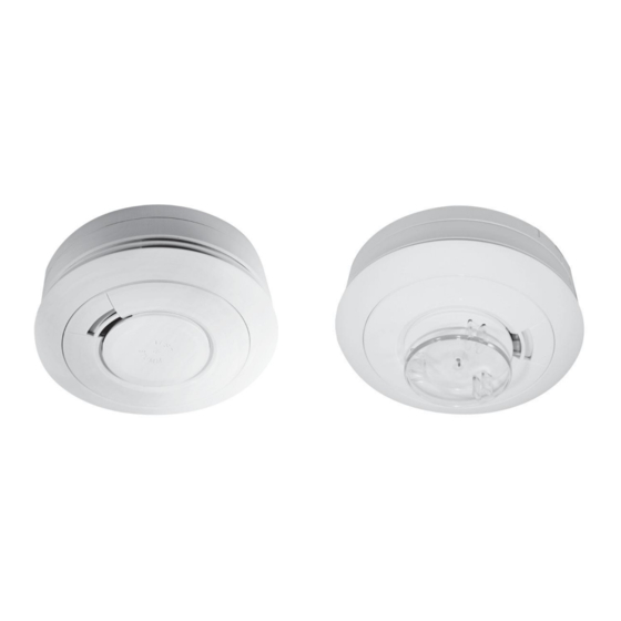
EIB605 Smoke Alarm Series
EIB603 Heat Alarm Series
Instructions
Read and retain carefully for as long as the product is being used . It contains vital information on the operation and installation
of your Alarm. The leaflet should be regarded as part of the product.
If you are just installing the unit, the leaflet must be given to the householder. The leaflet is to be given to any subsequent user.
Advertisement
Table of Contents

Related Manuals for Brooks EIB605

Summary of Contents for Brooks EIB605
- Page 1 Battery Powered Smoke & Heat Alarms EIB600 Series EIB605 Smoke Alarm Series EIB603 Heat Alarm Series Instructions Read and retain carefully for as long as the product is being used . It contains vital information on the operation and installation of your Alarm.
- Page 2 Table 1 9V Replaceable Battery Optional Model Alarm Hardwired Capability RF Module Type Interconnect Supplied Model No. EIB605C Optical EIB605MRF EIB603C Heat EIB605MRF 10 Year Lithium Battery Built-in Optional Hardwired Model Alarm Capability RF Module Interconnect Type Supplied Model No. EIB605TYC Optical EIB605MTYRF...
-
Page 3: Table Of Contents
Page CONTENTS QUICK START GUIDE LOCATION & POSITIONING INSTALLATION INTERCONNECTION - HARD WIRED TESTING, MAINTENANCE & POWER SUPPLY MONITORING FIRE SAFETY ADVICE SMOKE ALARM LIMITATIONS RADIOLINK ACCESSORIES GETTING YOUR ALARM SERVICED 10 FIVE YEAR GUARANTEE 11 TROUBLESHOOTING 12 CONTACT US... -
Page 4: Quick Start Guide
1. Quick Start Guide LOCATE CORRECT SITING POINT FIX BASEPLATE TO CEILING ALARM SHOULD BE CEILING MOUNTED AT LEAST 300MM FROM WALLS & OBSTRUCTIONS, IDEALLY CENTRALLY IN ROOM/AREA CONNECT BATTERY SNAPS 9V REPLACEABLE BATTERY MODELS ONLY 9 VO LT BATTERY BATTERY CONNECTORS BASE OF... - Page 5 Quick Start Guide PLACE ALARM & TWIST ON TO BASE ON 10 YEAR LITHIUM BATTERY ALARM MODELS - TWISTING THE UNIT ON TO THE BASE AUTOMATICALLY CONNECTS THE BATTERY TEST ALARM PRESS THE TEST BUTTON TEST ALARM AT LEAST WEEK LY...
-
Page 6: Location & Positioning
Note: Certain alarms may be supplied (on request) with the appropriate RF module fitted. SMOKE ALARMS - EIB605 Series Sufficient smoke must enter your Smoke Alarm before it will respond. Your Smoke Alarm needs to be within 7.5 metres of the fire to respond quickly. Smoke Alarms also need to be in positions where they can be heard throughout the property, so they can wake you and your family in time for everyone to escape. - Page 7 Your first Smoke Alarm should be located between the sleeping area and the most likely sources of fire (living room, kitchen for example), but it should not be more than 7.5 metres from the door to any room where a fire may start and block your escape from the house.
- Page 8 Multi-Storey Dwellings If your home has more than one floor, at least one Alarm should be fitted on each level (see Figure 1). Preferably the units should be interconnected so as to give sufficient warning throughout the property. RadioLINK plug-in modules are ideal in this situation as the units will then interconnect using Radio Frequency (RF) signals - so no wiring is required.
- Page 9 f o l l o w e d Figure 1 k i t c h e n ( w h e r e Heat Alarm is For minimum protection - Smoke Alarm on each storey - in each sleeping area Kitchen Bedroom - every 7.5 metres of hallways and...
- Page 10 recommended) and then the dining room. Consideration should be given to installing Smoke Alarms in any bedrooms where fires might occur, for instance, where there is an electrical appliance such as an electric blanket or heater, or where the occupant is a smoker. In addition, consideration should be also given to installing Smoke Alarms in any rooms where the occupant is unable to respond very well to a fire starting in that room, such as an elderly or sick person or a very young child.
-
Page 11: Locations To Avoid
On a Sloping Ceiling With a sloping or peaked ceiling install a Smoke Alarm within 600mm of the peak or a Heat Alarm within 150mm of the peak (measured vertically). If this height is less than 600mm for Smoke Alarms or 150mm for Heat Alarms the ceiling is regarded (see Figure 4). - Page 12 • Do not locate in insect infested areas. Small insects getting into the smoke detector chamber can cause intermittent alarms. DON’T place Heat Alarms in any of the following areas: • Bathrooms, shower rooms or other rooms where the unit may be triggered by steam or condensation.
-
Page 13: Installation
3. Installation Installation Procedure 1. Select a location complying with the advice in Section 2. 2. Remove the mounting plate from the Smoke/Heat Alarm by twisting it in an anti-clockwise direction (see Figure 5). 3. Place the mounting plate on the ceiling exactly where you want to mount the Alarm. - Page 14 a part of the building, say the front wall of the building and then installing all mounting plates in the same orientation with respect to this (see figure 6). Front Wall Front Wall Mounting Plate Mounting Plate Orientate all mounting plates in the same direction Large...
- Page 15 8. Press the Test button on each alarm to ensure that the Alarm works (see Figure 7a for Smoke Alarm & 7b for Heat Alarm). 9. For hard-wired interconnected Alarms, hold down the Test button on each Alarm in turn and check that all other interconnected Alarms sound.
- Page 16 PUSH UP CATCH & TWIST BREAK OFF SMALL PILLAR ALARM ANTI-CLOCKWISE TO REMOVE How to Tamperproof How to Remove Figure 8a Figure 8b TAMPERPROOF SCREW Line up the screw (not SELF TAPPING “U” SCREW supplied) shaped recessed area shown in figure 8c and screw firmly home.
-
Page 17: Interconnection - Hard Wired
4. Interconnection - Hard Wired A combined maximum of 12 Smoke Alarms and/or Heat Alarms may be wired together such that when one unit senses fire all other units sound a warning. This helps ensure the alarm will be heard throughout the property. Do not connect to any other device as it may damage the unit or affect performance. - Page 18 from the sensing chamber, making it insensitive. It is essential that all such ceiling openings be closed with silicone sealant or similar. 1. Run the two core cable to the Alarm locations. 2. Bring the cable through the opening in the mounting plate (before screwing it to the ceiling) see figure 9b.
-
Page 19: Testing, Maintenance & Power Supply
Install and connect all the other Alarms similarly. Now test the first Alarm by pressing and holding the Test button (this may take up to 5 seconds). The red indicator light will flash about once a second on the first Alarm and all other Alarms should sound. Check all the other Alarms similarly. - Page 20 - If they are interconnected using RadioLINK modules, hold down the Test button until the blue light on the cover of the Alarm illuminates. Check that all other Alarms sound. - Release the Test button. The Alarm and all connected Alarms should stop sounding.
- Page 21 If you installed Alarms with RadioLINK modules and did not House Code them, you may be receiving alarm signals from a neighbouring system. This can be easy rectified by “House Coding” your Alarms - see booklet „RF Modules for Battery Powered Smoke &...
- Page 22 2. A Heat Alarm is beeping about once a minute. - If it is a 9V Replaceable Battery model then replace the battery. - If it is a 10 Year Lithium Battery model then replace the entire unit. 3. On 10 Year Lithium Battery models with RadioLINK modules (fitted) - If the blue light flashes every 10 seconds it indicates that the RF battery is depleted and the RadioLINK module must be replaced.
- Page 23 The latest design, materials and manufacturing techniques have been used in the construction of Brooks Alarms to minimise the effects of contamination. However it is impossible to completely eliminate the effect of dust and insect contamination, and therefore, to prolong the life of the Alarm you must ensure that it is kept clean so that excess dust does not build up.
- Page 24 In certain circumstances even with regular cleaning, contamination can build up in the smoke sensing chamber causing the alarm to sound. If this happens the Smoke Alarm must be returned for servicing or replacement. Contamination is beyond our control, it is totally unpredictable and is considered normal wear and tear. For this reason, contamination is not covered by the guarantee and a charge is made for all such servicing work.
-
Page 25: Fire Safety Advice
6. Fire Safety Advice When using household protective devices, basic safety precautions should always be followed, including those listed below • Please read all instructions. • Rehearse emergency escape plans so everyone at home knows what to do in case the alarm sounds. •... - Page 26 • If Alarm has been damaged in any way or does not function properly, do not attempt a repair. Return the Alarm (see Section 9). • This appliance is intended ONLY for premises having a residential type environment. • This is not a portable product. It must be mounted following the instructions in this instruction leaflet.
- Page 27 This device cannot protect all persons at all times. It may not protect against the three most common causes of fatal fires: 1. Smoking in bed. 2. Leaving children at home alone. 3. Cleaning with flammable liquids, such as petrol. Further information can be obtained from the Fire Brigade.
- Page 28 4. Call the Fire Brigade from a neighbour‟s house or mobile phone. Remember to give your name and address. 5. NEVER re-enter a burning house. 7. Alarm Limitations Limitations of Smoke/Heat Alarms Smoke/Heat Alarms have significantly helped to reduce the number of fire fatalities in countries where they are widely installed.
- Page 29 as recommended in this leaflet very significantly improve the probability of early detection. • The Smoke/Heat Alarm may not be heard. • RadioLINK may not work due to interference or due to the signal being blocked by furniture, renovations etc. •...
-
Page 30: Radiolink Accessories
8. RadioLINK Accessories EIB605MRF RadioLINK Interconnect module for the 9V Replaceable Battery models. It plugs into the rear of the Alarm. This ensures that when one Alarm senses fire, all units sound to give an alarm through-out the house - (see Table 1). EIB605MTYRF RadioLINK Interconnect module for the 10 Year Lithium Battery models. -
Page 31: Five Year Guarantee
This guarantee excludes incidental and consequential damage. If this Alarm should become defective within the guarantee period, it must be returned to Brooks, with proof of purchase, carefully packaged, with the problem clearly stated (see Section 9). We shall at our discretion repair or replace the faulty unit. -
Page 32: Troubleshooting
11. Troubleshooting Alarms sound for no apparent reason • Check for fumes, steam, etc. from the kitchen or bathroom. Paint and other fumes can cause nuisance alarms. • Check for any sign of contamination such as cobwebs or dust. Clean the alarm as described in Section 5 if necessary. - Page 33 • On the 10 Year Lithium Battery models ensure the unit is twisted fully home on the mounting plate, as this connects the battery.
- Page 34 The crossed out wheelie bin symbol that is on your product indicates that this product should not be disposed of via the normal household waste stream. Proper disposal will prevent possible harm to the environment or to human health. When disposing of this product please separate it from other waste streams to ensure that it can be recycled in an environmentally sound manner.
-
Page 36: Contact Us
12. Contact Us BROOKS AUSTRALIA 4 PIKE ST, RYDALMERE, NSW 2116. 1300 78 FIRE www.brooks.com.au © Brooks 2010 P/N B17078 Rev 0...
Need help?
Do you have a question about the EIB605 and is the answer not in the manual?
Questions and answers