Table of Contents
Advertisement
Quick Links
Advertisement
Table of Contents

Related Manuals for Genie IPB2AFIR Series


Summary of Contents for Genie IPB2AFIR Series
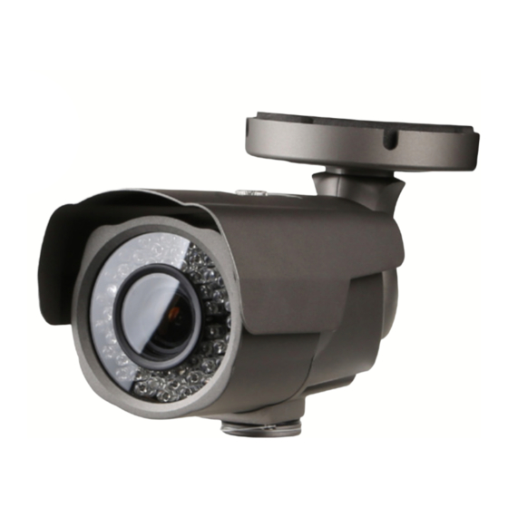
- Page 1 IPB2AFIR Series HD IP Fixed High Brightness Bullet Cameras User Manual...
-
Page 2: Safety Information
Safety Information CAUTION RISK OF ELECTRIC SHOCK. DO NOT OPEN. CAUTION : TO REDUCE THE RISK OF ELECTRIC SHOCK, DO NOT REMOVE COVER (OR BACK) NO USER SERVICEABLE PARTS INSIDE. REFER SERVICING TO QUALIFIED SERVICE PERSONNEL. Precaution Precaution This exclamation point symbol is This exclamation point symbol is intended to alert the user to the intended to alert the user to the... -
Page 3: Important Safety Instructions
Important Safety Instructions 1. Read these instructions - All safety and operating instructions should be read before the product is installed or operated. 2. Keep these instructions - The safety, operating and user instructions should be retained for future reference. 3. -
Page 4: Product And Accessories
Introduction - Product & Accessories Please check if all the camera and accessories are included in the package. Cables Camera Torx Wrench Screw & Plastic Anchor-4pcs Test Monitor Cable Template Sheet Manual CD Quick Manual... -
Page 5: Part Name
Introduction - Part Name Sunshield Lens Pan/Tilt Stoper Screw Control Board Bracket Con Cap... -
Page 6: Specification
Introduction - Specification Model Number IPB2AFIRS IPB2AFIRL Image Sensor 1/2.8” 2MP CMOS Total Pixels 2000 (H) x 1241 (V) Effective Pixels Aspect Ratio HD: 16:9, SD: 4:3 Zoom Ratio Optical x8 (Digital x12) Focal Length Auto Focus 3 - 10.5 mm, F1.4, P-Iris Lens 3.0 ~ 10.5 mm 6.3 ~ 50 mm... -
Page 7: Installation
Installation - Installation Before installing your camera, you have to read the following cautions. 1. You have to check whether the location can bear ve times of the weight of your camera. 2. Don’t let the cable to be caught in improper place or the electric line cover to be damaged. Otherwise it may cause a breakdown or re. - Page 8 Installation - Inserting/Removing SD Memory Card The memory card is an external data storage device that has been developed to o er an entirely new way to record and share video, audio, and text data using digital devices. Micro Recommended SD Card Speci cation (Not Included) - Type: Micro SD (SDHC) - Manufacturer: Transcend, Kingston, Toshiba, Sanddisk...
- Page 9 Installation - Cabling White : DIN+ Yellow : GND Black : DOUT- Red : DOUT+ Alarm In Alarm Out Audio Out Audio In Audio In Alarm Out Cable of the audio input device should connect to audio in It connects to the alarm lights, siren or lamps and the sensor and GND pin of the cable slot and audio input device is types are normal open and normal close.
-
Page 10: Network Setup
Network Setup - IP Installer 1. Run IP Installer Run the manual CD and IP installer in S/W folder. Change the port as necessary when the network type is set to STATIC. Click on Network Adaptor selection Menu (NIC) after run A ‘Port Forwarding’... -
Page 11: Quick Start Of Network Connection
Network Setup - Quick Start of Network Connection Please follow the steps below to complete Configure the IP Camera’s TCP/IP settings as you normally do any other PCs on your network by providing a proper IP the initial setup of the network function. address, subnet mask, default gateway, and DNS server. -
Page 12: Initial Setup Via A Crossover Cable
Network Setup - Initial Setup via a Crossover Cable This section provides a guide on how to Now you will be able to access the viewer software within the IP Camera. connect the IP Camera to your PC/Laptop for initial setup. Open Internet Explorer and type the IP address of 192.168.1.80 Please follow the instructions in the order (default IP of the IP Camera from the factory) into the Address Bar... -
Page 13: Ddns Registration
Network Setup - DDNS Registration If you have DYNAMIC IP service from your Internet Service Provider (ISP), you can’t tell the current IP address of the IP Camera. To solve this problem, you have to register to our DDNS service. At first, you have to check if you are using dynamic addressing. -
Page 14: Guide To Network Environment
Network Setup - Guide to Network Environment Please configure the IP Camera at the 5. The following descriptions are several basic network scenarios. Determine which scenario describes your network. installation site. You must determine your If your network does not match one of the scenarios below network scenario in order to configure the IP and you are unsure how to setup your IP Camera, contact Camera with the proper TCP/IP settings. - Page 15 Network Setup - Setup Case A, B Configure your IP Camera's TCP/IP properties Case A: as follows : Dynamic IP + Personal Router [Most SOHO] Network Type : STATIC (even though you have Dynamic IP from your ISP, use STATIC on the IP Camera) Camera Internet Address : A private IP address such as...
- Page 16 Network Setup - Setup Case C, D Case C: Case D: Static(Fixed) IP [Dedicated line directly Dynamic IP + DSL/Cable Modem [Connected to the IP Camera] directly to the IP Camera] Camera Camera Phone Line or CATV Cable/xDSL Modem (ISP Provided) Public Line Gateway or Router at ISP...
-
Page 17: Port Forwarding
Network Setup - Port Forwarding After entering the correct TCP/IP settings, you are ready for ‘Port Forwarding’(Cases A, B). Please record the TCP/IP settings of your IP Camera for future reference. You may need this information to access your IP Camera and to configure ‘Port Forwarding’... -
Page 18: Starting Ip Camera
Network Setup - Starting IP Camera After forwarding correctly the Web Port, Video Port, Control Port and two Audio Ports through your router (if applicable), install the IP Camera in a proper location. Locate the serial number located on the label attached to the bottom of the IP Camera, you will need this for DDNS registration. -
Page 19: Web Viewer Screen
Web Viewer Screen - Basic Screen Web viewer is optimized with Windows XP or above version Control tab button. Click it to extend the panel to control the function of web-viewer. See the next page for detail. and explorer browser. Live video display. -
Page 20: Control Tab
Web Viewer Screen - Control Tab When the image goes unsmoothly because of bad network connection, it stored image during setup time and shows the image on the live view screen. User will see the delayed images as much as setup time. Video stream button. - Page 21 Web Viewer Screen - Control Tab Speaker Control. Enable/Disable Audio stream received from the camera and Volume control of the speaker in the computer. Mic Control. Enable/Disable the Audio stream to the camera. Motion Detection. Enable or Disable motion detection function.
-
Page 22: Camera Setup
Camera Setup - Camera Setup Brightness Using this control, brightness of image can be adjusted to meet your preference. Sharpness Using this control, sharpness of image can be adjusted to meet your preference. Mirror Reverse the video from side to side. Flip Reverse the video from up to down. - Page 23 Camera Setup - Camera Setup White Balance Auto: The camera performs white balance automatically. Auto-Ext: WB will be done under the assumption of special illumination like halogen. Indoor: WB will be done under the assumption of the Indoor illumination. Outdoor: WB will be done under the assumption of the Sun light. One-Push Mode: WB is executed once on the scene you designated.
- Page 24 Camera Setup - Camera Setup _Type1 Zoom / Focus Adjust the zoom or focus by clicking the ‘+’ or ’ - ’ button. Mode This function will prevent flickering screen from the natural outdoor light or indoor light. Flickerless(Read Only) Day &...
-
Page 25: Video Setup
Setup - Video Setup Resolution Live Video Channel Setup Select the video resolution. The video can be configured to variaty settings with a combination of codec and resolution. Available resolution can be depends on the codec setup between The camera performance has to be considered when setting the channels. - Page 26 Setup - Video Setup GOP(Group of Pictures) Size Bitrate Mode Select the bit rate control scheme of video compression Set up the number of frames (P-frame) which contain only from CBR (Constant Bit Rate) or VBR (Variable Bit Rate). changed information based on basic frame (I-frame). Regarding videos with lots of movement, if you set GOP size Quality bigger, only the number of P-frames is bigger.
- Page 27 Setup - Video Setup RTP Multicast Check RTP Multicast On/Off. To activate RTP Multicast, 1. Click “Start” button, 2. Enter accessible RTP Multicast IP, port for video stream control, RTP packet TTL, 3. Click “Apply” button. Click “Stop” button to disable RTP Multicast. It is possible to set each RTP Multicast for CH1~3.
-
Page 28: Audio Setup
Setup - Audio Setup Input Gain Adjust the input gain of audio. Output Gain Adjust the output gain of audio. Output gain 0 is mute. Click ‘Apply’ to make above setting effective. - Page 29 Setup - Date/Time Display the current time. When Date/Time is displayed, deletion of the motion detection mask on the area of Date/Time display are strongly recommended to prevent misdetection on changing numbers. However, motion detection will be disabled at the area that masks are off.
-
Page 30: Tcp/Ip Setup
Setup - TCP/IP Setup Network Type Preferred DNS Server Define network IP address type from the Static Mode for the Define the DNS server IP address. Format is same as the IP fixed IP or the Dynamic Mode by the dynamic IP address. address. - Page 31 Setup - RTSP RTSP Session TimeOut Check on the check box to enable ‘RTSP Settion Timeout’ function. Unit is sec. Click ‘Apply’ to make above setting effective.
- Page 32 Setup - ONVIF Authentication None : Allows to access without ONVIF authentication. WS - Username token : Allows to access with WS-User Token of ONVIF authentication. WS + Digest : Allows to access with WS-User Token and Digest of ONVIF authentication. Click ‘Apply’...
-
Page 33: Ddns Setup
Setup - DDNS Setup DDNS Disable If it is selected, DDNS service does not work. Basic DDNS Please register the camera in net4c site so as to use net4c DDNS. Insert the serial number shown on the screen in the serial entry field. - Page 34 Setup - HTTPS Setup Secure Connection System Install a public certificate Secure Connection System chooses a method of security A certificate issued by Certificate Authority can be installed connection. to the camera and the installed certificate can be deleted. <How to install or delete the certificate> HTTP 1) Input the description(name) of a certificate.
-
Page 35: Snmp Setup
Setup - SNMP Setup SNMP Setup The information of camera system can be known and configured with SNMP. SNMP V3 Secure Setup The changes for configuration use version 3 and username and password should be certified at that time. Username Username is the information of user account for user authentication. - Page 36 Setup - Status This menu will show you all the information of Network setting in the camera. However, you cannot change those here.
-
Page 37: Alarm Input Setup
Setup - Alarm Input Setup Input Device Setup Action Select input device type from OFF / N.O. / N.C. Define a counter action from Alarm Output / Alarm Image Transfer / Camera Action when Alarm Input is detected. Operation Action Description Ignore this Input sensor. -
Page 38: Motion Detection Setup
Setup - Motion Detection Setup Activation Time Action Select activation time from Always / Only Scheduled Time. Define a counter action from Alarm Output / Alarm Image transfer when motion is detected. An alarm is activated whenever motion is Always detected. -
Page 39: Schedule Setup
Setup - Schedule Setup Schedule function enables to transfer series of still images in Activation Time a time interval specified via E-mail or FTP. (For more detail, Select activation time from Always / Only Scheduled Time. see ‘Transfer Setup’ in this chapter) Always Transfer image at all times. -
Page 40: Transfer Setup
Setup - Transfer Setup This function is enabled when the codec is set to “MJPEG” for channel 2 at “Setup-Video setup”. Transfer Mode Image Transfer method is selected from Disable, FTP and E-Mail (SMTP). To use image transfer, FTP and SMTP in the next sections must be configured properly. - Page 41 Setup - FTP Setup To transfer/save the image to the relevant sites through FTP, Port then FTP needs to be setup. Define the FTP Server Port. If Port is not appropriate, it is impossible to access to FTP Server. Use Passive Mode Check it to use Passive mode for FTP transfer.
-
Page 42: Smtp Setup
Setup - SMTP Setup To send/save the image to the relevant sites by Email, SMTP E-Mail Sender needs to be setup. Define the e-mail address of E-Mail Sender. It will be displayed as the sender when the camera sends an E-mail. Plain, SSL/TLS Select Security mode of SMTP from Plain or SSL/TLS. -
Page 43: Sd Card Setup
Setup - SD CARD Setup SD Card Record Capacity Warning E-mail If it is set to On, the image is saved into the SD card as well. If it is set ON and remained space of SD card reach to less than 8MB, a warning e-mail will be sent to the e-mail It will setup OFF automatically when SD card doesn't applied. -
Page 44: Users Setup
Setup - Users Setup Users Modify List all the user accounts for authentication. Modify the information of the user accounts registered. For admin account, only Password and Auto Login function can be modified. Register a new user Delete Delete the selected user account. Admin account cannot be deleted. -
Page 45: Date/Time Setup
Setup - Date/Time Setup Timezone Setup Synchronize with the time server Choose Timezone for camera. It will be activated after Choose time server available to connect to current camera. clicking ‘Apply’ button. Date & Time will be updated automatically every hour Prior to setting below ‘New Camera Date &... -
Page 46: Firmware Update
Setup - Firmware Update Browse... Firmware Version Warning: It shows the current Firmware Version in the system. 1. Do not turn off the power of camera during the Firmware update. Otherwise, the system can be stuck to be unstable. Firmware Filename If updating is finished, the system will be rebooted Designate the Firmware file name in your computer by automatically. -
Page 47: Default Set
Setup - Default Set Reset to the factory defaults Return the setup to the factory default. Reset all Settings to the factory defaults. Except Except Network related settings, reset Network Settings all others to the factory defaults. Except Network Setting Except AutoMap data and Network and AutoMap Data related settings, reset all others to the... - Page 48 Setup - Restart If you click the ‘RESTART’ menu, a message box will be shown to confirm. Click the ‘Ok’ button to restart.
- Page 49 Setup - System Start, Network Connection Status(Including IP Address), Changing System Time, Changing Video Setup, Network Setup and Event(Alarm / Motion) Alert will be recorded. Total 884 pcs logs in each category and the rest will be deleted.
- Page 50 SD Card Search - Search Date of stored image Choosing the date to nd the stored events. Stored Events(Schedule / Motion / Alarm) The interval of stored time and number of stored images in the Event Setup can be di erent. Page No.
- Page 51 Appendix A : Current TCP/IP Settings If your IP settings are obtained automatically, you could use the MS-DOS prompt (or Command Prompt) to determine your IP address. For information on how to do this, please read the FAQ. 1. Windows 98 / ME Users 2.
- Page 52 Appendix - B : Changing IP address and subnet mask 1. Windows 98 / ME Users 2. Windows 2000 or XP Users 3. Windows Vista or 7 Users Start Start Start Setting Control Panel Control Panel Control Panel Network and Network and Dial-up sharing center Connection or...
-
Page 53: C : Port Forwarding
Appendix - C : Port Forwarding After assigning the IP Camera a web server For Linksys BEFSR41 Cable/DSL routers: port and video server port you must use Port 1) Open a web browser and type http://192.168.1.1 into you Forwarding. (for cases A, B) Address bar. - Page 54 Appendix - C : Port Forwarding For Netgear RP614 routers: 1) Input http://192.168.0.1 in address bar of web browser. http://192.168.0.1 is the default IP address. 2) If it asks ID and password, input admin as ID and password as password. 3) Click “Port Forwarding”...
- Page 55 Appendix - My POWER light is not on? I can’t connect!! Power is not being supplied to the unit. Please use the power In the case of a connection failure. supply shipped with the unit and verify that a power source Modem Reboot >...
-
Page 56: Specifications
Specifications - Dimension Unit: mm 96.7 96.7 247.8 225.6... - Page 57 GENIE CCTV LTD. CCTV House, City Park, Watchmead, Welwyn Garden City, Hertfordshire, AL7 ILT Tel: +44 (0) 1707 330541 Fax: +44 (0) 1707 330543 www.geniecctv.com Edition. GN-May 2014...
Need help?
Do you have a question about the IPB2AFIR Series and is the answer not in the manual?
Questions and answers