Invacare TDX SP2 series User Manual
Hide thumbs
Also See for TDX SP2 series:
- User manual (128 pages) ,
- Service manual (56 pages) ,
- Service manual (56 pages)

Related Manuals for Invacare TDX SP2 series


Summary of Contents for Invacare TDX SP2 series
- Page 1 Invacare® TDX SP2® Series EN Power Wheelchair User Manual This manual MUST be given to the user of the product. BEFORE using this product, read this manual and save for future reference.
- Page 2 All rights reserved. Republication, duplication or modification in whole or in part is prohibited without prior written permission from Invacare. Trademarks are identified by ™ and ®. All trademarks are owned by or licensed to Invacare Corporation or its subsidiaries unless otherwise noted.
-
Page 3: Table Of Contents
4.2 Using the cane holder ......26 Contents 4.3 Using the KLICKfix adapter ..... . . 26 5 Adjusting the mobility device to the user's seating 1 General . - Page 4 5.6.3 Adjusting the backrest angle (Modulite seat 5.12 Vari-A legrests ....... . 49 unit) .
- Page 5 5.14.6 Unlocking and swivelling the calf pad backward 7.2.3 How to charge the batteries ....72 when alighting ......62 7.2.4 How to disconnect the batteries after 5.14.7 Adjusting the angle–adjustable foot plate .
- Page 6 10.2 Disposal ........89 11Technical data .
-
Page 7: General
If you find that the font size in the print version of the user manual Indicates a hazardous situation that could result in is difficult to read, you can download it as a pdf from the Invacare damage to property if it is not avoided. -
Page 8: Intended Use
You should immediately contact an authorized European weather conditions. When equipped with an appropriate Invacare dealer if the usability of your mobility device lighting system, the vehicle is suitable for use on public roads. is restricted due to: 1.6 Indications... -
Page 9: Warranty
General Or if you have the feeling that something is wrong with your mobility device. 1.8 Warranty The terms and conditions of the warranty are part of the general terms and conditions particular to the individual countries in which this product is sold. 1.9 Service life We estimate a service life of five years for this product, provided it is used in strict accordance with the intended use as set out in this... -
Page 10: Safety
Invacare® TDX SP2® Series 2 Safety WARNING! Risk of damage or injury if mobility device is accidentally set into motion 2.1 General safety notes – Switch the mobility device off before you get in, get out or handle unwieldy objects. - Page 11 Safety WARNING! CAUTION! Risk of injury when transferring mobility device Risk of injury if maximum permissible load is to a vehicle for transport with the occupant exceeded seated in it – Do not exceed the maximum permissible load (refer – It is always better to transfer the mobility device to a to 11 Technical data, page 90).
-
Page 12: Safety Information On The Electrical System
Corroded electrical components due to water, liquid – Do not connect any electric devices to your mobility exposure, or incontinent users can result in death, device that are not expressly certified by Invacare for serious injury, or damage. – Minimize exposure of electrical components to water this purpose. -
Page 13: Safety Information On Electromagnetic Interference
Safety DANGER! Risk of damage to the wheelchair Risk of death or serious injury A failure in the electric system can lead to unusual Failure to observe these warnings can cause an electrical behavior such as continuous light, no light, or noises short resulting in death, serious injury, or damage to from the magnetic brakes. -
Page 14: Safety Information On Driving And Freewheel Mode
Invacare® TDX SP2® Series WARNING! WARNING! Risk of malfunction due to electromagnetic Risk of injury if the mobility device tips over interference – Inclines and declines can only be travelled up to the – Do not switch on or operate portable transceivers or... - Page 15 Safety WARNING! WARNING! Risk of injury if the mobility device tips over Risk of breaking down in adverse weather (continued) conditions, i.e. extreme cold, in an isolated area – Never use the mobility device to transport more than – If you are a user with severely limited mobility, we one person.
-
Page 16: Safety Information With Regard To Care And Maintenance
Such repair lowered during normal travelling. and/or service MUST be performed by a qualified technician. Contact a dealer or Invacare technician. WARNING! Tipping hazard if antitippers are removed, CAUTION! -
Page 17: Safety Information Regarding Changes And Modifications To The Mobility Device
DANGER! Seating systems, additions and accessory parts which Risk of serious injury or damage have not been approved by Invacare for use with Use of incorrect or improper replacement (service) this mobility device can affect the tipping stability and parts may cause injury or damage increase tipping hazards. -
Page 18: Safety Information On Wheelchairs With A Lifter
– Some maintenance work which is described in this A retrofitted backrest which is not approved by Invacare manual and can be carried out by the user without for use with this mobility device may overload the problems require the correct tools for proper work. -
Page 19: The Position Of The Labels On The Product
Safety CAUTION! Important information regarding speed reduction Risk of injury if the wheelchair tips over with raised lifter – Never exceed the maximum permissible load (see – If the lifter has been raised above a certain point, the chapter 11 Technical data, page 90). drive electronics considerably reduces the speed of –... - Page 20 Invacare® TDX SP2® Series If the mobility device is fitted Warning regarding the use of with a tray, it is imperative the lifter. that it is removed and safely For details see below. stowed when transporting the Indication of the maximum mobility device in a vehicle.
- Page 21 Do not lean out when the lifter is raised! as a vehicle seat, but only if it is equipped with a headrest that has been approved by Invacare for this purpose. • Do not drive up or down slopes when the lifter is Please always make sure...
- Page 22 Invacare® TDX SP2® Series Do not allow any body parts to get under a raised seat! Never drive with two people! Never drive over uneven surfaces when the lifter is raised! Read the user manual 1578997-A...
-
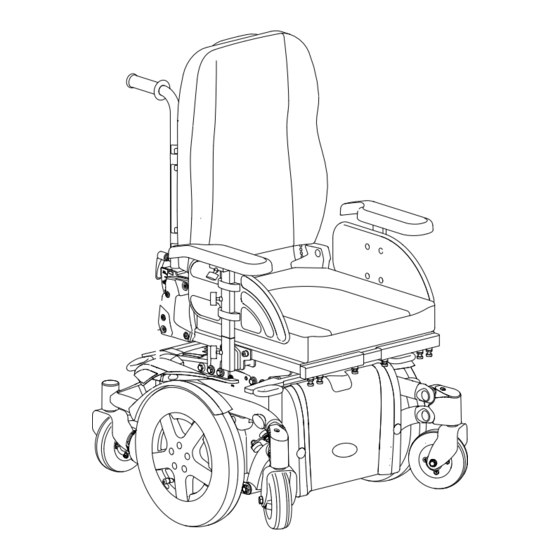
Page 23: Components
Information regarding operation of the lifter at temperatures of less than 0 °C – Invacare mobility aids are fitted with safety mechanisms that prevent capacity overload of the electronic components. At operating temperatures below freezing point this can, in particular, lead to the lifter actuator being shut down after approx. - Page 24 Invacare® TDX SP2® Series CAUTION! Risk of tipping, if the speed limiter sensors fail when the lifter is raised – If you find that the speed reduction function is not working when the lifter is raised, do not drive with the lifter raised and immediately contact an authorized Invacare dealer.
-
Page 25: Accessories
Accessories 4 Accessories 4.1 Postural belts A postural belt is an option which can either be fixed to the mobility device ex-works or can be retrofitted by your specialist dealer. If your mobility device is fitted with a postural belt, your specialist dealer will have informed you about fitting and usage. -
Page 26: Using The Cane Holder
Invacare® TDX SP2® Series The buckle should be positioned as centrally as possible. In doing accessories such as the cellphone case supplied by Invacare, which so, carry out adjustments on both sides as much as possible. you can use to transport your cellphone, sports glasses etc. - Page 27 Accessories instructions which are available from your Invacare dealer or directly from Invacare. More information on the KLICKfix system is available at http://www.klickfix.com. 1578997-A...
-
Page 28: Adjusting The Mobility Device To The User's Seating Posture
If the mobility device does not perform to specifications, IMMEDIATELY turn the mobility device Off and reenter set-up specifications. Contact Invacare, if mobility device still does not perform to correct specifications. 1578997-A... -
Page 29: Adjustment Possibility For Remote
Adjusting the mobility device to the user's seating posture CAUTION! CAUTION! Damage to mobility device and accident hazard Risk of the remote being pushed backwards It is possible that collisions can occur between mobility during an accidental collision with an obstacle, device components due to various combinations of such as a doorframe or table, and the joystick adjustment options and their individual settings... -
Page 30: Adjusting The Height Of The Remote (Only For Swing-Away Remote Holders)
Invacare® TDX SP2® Series 5.3 Adjustment options for the Modulite seat 5.2.2 Adjusting the height of the remote (only for swing–away remote holders) unit 5.3.1 Adjusting the height of the armrests Requirements: • 1 x 6 mm Allen key Loosen the Allen screw A. -
Page 31: Adjusting The Position Of The Armrest In Depth
The description of how the width is adjusted is contained in the service instructions for this mobility device. The service instructions can be ordered from Invacare. However, they contain instructions for specially trained service technicians and describe operations that Loosen screw A. -
Page 32: Adjusting The Seat Depth (Modulite Seat Unit)
The service instructions the same seat depth is set on both sides. can be ordered from Invacare. However, they contain instructions for specially trained technicians and describe operations that are not intended for the end user. -
Page 33: Adjustment Options For Max Seat
Adjusting the mobility device to the user's seating posture 5.4 Adjustment options for Max seat 5.4.1 Changing the armrest position Requirements: • 1 x 6 mm Allen key Unscrew screw A with Allen key. Adjust armrest to required height. Retighten the screw. 5.4.3 Adjusting the width of the armrests Requirements: •... -
Page 34: Adjusting The Seat Depth
Invacare® TDX SP2® Series Loosen the screws (1). Adjust the armrest to the desired width. Retighten the screw. Repeat this procedure for the second armrest. 5.4.4 Adjusting the seat depth CAUTION! Risk of damage to the power wheelchair if the... -
Page 35: Adjusting The Seat Angle
Adjusting the mobility device to the user's seating posture 5.5 Adjusting the seat angle Loosen all bolts on both sides. Set the required angle. CAUTION! Retighten the bolts. Adjusting the seat tilt or the backrest angle changes the geometry of the mobility device and 5.6 Adjusting the backrest directly influences its dynamic stability! –... -
Page 36: Adjusting The Width Of The Backrest (Modulite Seat Unit)
For a replacement description, see the service instructions for this mobility device. The service instructions can be ordered from Invacare. However, they contain instructions for specially trained service technicians and describe operations that are not intended for the end user. -
Page 37: Adjusting The Backrest Angle (Modulite Seat Unit)
Adjusting the mobility device to the user's seating posture 5.6.3 Adjusting the backrest angle (Modulite seat On both sides, loosen and remove the upper backrest screw A. Set the required backrest angle. unit) Use scale B on the backrest for this purpose. Ensure that you CAUTION! set the same angle on both sides. -
Page 38: Adjusting The Backrest Angle (Max Seat)
Invacare® TDX SP2® Series 5.6.4 Adjusting the backrest angle (Max seat) With the bolt, reattach the spindle to the backrest tube and secure the bolt. Requirements: Mount the seat plate and replace the seat cushion. • Crosstip screwdriver 5.6.5 Adjusting the tension adjustable backrest upholstery Remove the backrest cushion and the seat cushion. -
Page 39: Adjusting The Backrest Bend
Adjusting the mobility device to the user's seating posture 5.6.6 Adjusting the backrest bend Loosen the handwheels A and raise the push handles as far as possible. Figure 1 The backrest is designed with different angles as shown in figure 1. This allows for different adjustments according to how the backrest is mounted. - Page 40 Invacare® TDX SP2® Series Loosen the screws B and remove the backrest by lifting upwards. Put the backrest back by fitting it to the receivers on the tubes. Tighten the screws. Turn the backrest 180°. 1578997-A...
-
Page 41: Adjusting The Headrest
This can cause the neck to be hyperextended during collisions. – A headrest must be installed. The headrest optionally supplied for this mobility device by Invacare is perfectly suitable for use during transport. – The headrest must be adjusted to the user's ear height. -
Page 42: Adjusting The Height Of The Headrest Or Neckrest
Invacare® TDX SP2® Series Requirements: • Allen key 5 mm Loosen the knob A. Adjust the headrest or neckrest to the required height. Retighten the knob. Loosen the screws A , B or the clamping lever C. Adjust the headrest or neckrest to the required position. -
Page 43: Adjusting The Trunk Supports
Adjusting the mobility device to the user's seating posture 5.8 Adjusting the trunk supports 5.8.3 Adjusting the depth Requirements: 5.8.1 Adjusting the width • Allen key 5 mm Loosen the knobs A that hold the lateral supports. Loosen the screws A that allows the support pads to slide Adjust the supports to the desired width. -
Page 44: Laterally Adjusting The Tray
Invacare® TDX SP2® Series 5.9.1 Laterally adjusting the tray Loosen the wing-screw A. Adjust the tray to the desired depth (or remove it entirely). Re-tighten the screw. 5.9.3 Swinging the tray away to the side The tray can be swivelled up and away to the side to allow the user to get in and out of the mobility device. -
Page 45: Setting The Angle Of The Leg Rest
Adjusting the mobility device to the user's seating posture Hold the leg rest securely. Pull the lever (1). Push the leg rest into the required position. Remove the removable axle (1). 5.10.3 Setting the length of the leg rest Requirements: •... -
Page 46: Setting The Angle Of The Footplate
Invacare® TDX SP2® Series 5.10.4 Setting the angle of the footplate Retighten the bolt. Fold the calf pad back. Requirements: 5.11 Vari-F footrest • 1 x Allen key 5/32'' 5.11.1 Swivelling the footrest/legrest outward and/or removing The small unlocking button is located on the upper section of the footrest/legrest. -
Page 47: Setting The Angle
Adjusting the mobility device to the user's seating posture 5.11.2 Setting the angle CAUTION! Risk of injury due to incorrect adjustment of the footrests and legrests – Before and during every journey it is imperative to ensure that the legrests contact neither the caster wheels nor the ground Requirements: •... - Page 48 Invacare® TDX SP2® Series The end position of the footrest is determined by means of a rubber stop (1). Use the Allen key to loosen the screw (1) and swivel the footrest upward in order to access the rubber stop.
-
Page 49: Adjusting The Length Of The Legrest
Adjusting the mobility device to the user's seating posture Requirements: • 1 x 5 mm Allen key Move the rubber stop to the desired position. Re-tighten the counternut. Use the spanner to loosen the screw (1). Adjust to the desired length. Re-tighten the screw. -
Page 50: Setting The Angle
Invacare® TDX SP2® Series Loosen the locking knob (1) counter-clockwise at least one turn. Press the unlocking button (1) and swivel the footrest/legrest outward. Remove the footrest/legrest in an upward direction. 5.12.2 Setting the angle CAUTION! Risk of injury due to incorrect adjustment of the footrests and legrests –... -
Page 51: Setting The End Stop Of The Legrest
Adjusting the mobility device to the user's seating posture The end position of the legrest is determined by means of a rubber stop (1). Set the desired angle. The rubber stop can be screwed in or out A or pushed up or down B. - Page 52 Invacare® TDX SP2® Series Use the open-ended spanner to loosen the counternut (1). Hit the knob to release the locking mechanism. Move the rubber stop to the desired position. Re-tighten the counternut. Swivel the legrest upward in order to access the rubber stop.
-
Page 53: Adjusting The Length Of The Legrest
Adjusting the mobility device to the user's seating posture 5.12.4 Adjusting the length of the legrest Requirements: • 1 x 10 mm open-ended spanner CAUTION! Risk of injury due to incorrect adjustment of the footrests and legrests – Before and during every journey it is imperative to ensure that the legrests contact neither the caster wheels nor the ground Requirements:... -
Page 54: Unlocking And Swivelling The Calf Pad Backward When Alighting
Invacare® TDX SP2® Series 5.12.7 Unlocking and swivelling the calf pad backward when alighting Press the calf pad straight down. Use the Allen key to loosen the screws (1). Adjust to the desired position. Re-tighten the screws. Unlock the legrest and swivel outward. -
Page 55: Adjusting The Angle-Adjustable Foot Plate
Adjusting the mobility device to the user's seating posture 5.12.8 Adjusting the angle–adjustable foot plate Requirements: • 1 x 5 mm Allen key Use the Allen key to loosen the set screw on the foot plate (1). Adjust the foot plate to the desired angle or depth. Use the Allen key to loosen both set screws on the foot plate. -
Page 56: Setting The Angle
Invacare® TDX SP2® Series Pull the legrest upward until the desired angle has been achieved. Press the unlocking button (1) and swivel the footrest/legrest Lowering outward. Remove the footrest/legrest in an upward direction. 5.13.2 Setting the angle CAUTION! Risk of crushing –... -
Page 57: Adjusting The Length Of The Legrest
Adjusting the mobility device to the user's seating posture 5.13.3 Adjusting the length of the legrest Requirements: • 1 x 10 mm open-ended spanner CAUTION! Risk of injury due to incorrect adjustment of the footrests and legrests – Before and during every journey it is imperative to ensure that the legrests contact neither the caster wheels nor the ground Requirements:... -
Page 58: Unlocking And Swivelling The Calf Pad Backward When Alighting
Invacare® TDX SP2® Series 5.13.6 Unlocking and swivelling the calf pad backward when alighting Press the calf pad straight down. Use the Allen key to loosen the screws (1). Adjust to the desired position. Re-tighten the screws. Unlock the legrest and swivel outward. -
Page 59: Adjusting The Angle-Adjustable Foot Plate
Adjusting the mobility device to the user's seating posture 5.13.7 Adjusting the angle–adjustable foot plate Requirements: • 1 x 5 mm Allen key Use the Allen key to loosen the set screw on the foot plate (1). Adjust the foot plate to the desired angle or depth. Use the Allen key to loosen both set screws on the foot plate. -
Page 60: Setting The Angle
Invacare® TDX SP2® Series 5.14.3 Adjusting the length of the legrest CAUTION! Risk of injury due to incorrect adjustment of the footrests and legrests – Before and during every journey it is imperative to ensure that the legrests contact neither the caster... -
Page 61: Adjusting The Height Of The Calf Pad
Adjusting the mobility device to the user's seating posture Use the Allen key to loosen the screws (1). Adjust to the desired position. Use the open-ended spanner to loosen the nut (1) and remove. Re-tighten the screws. Adjust to the desired depth. Please observe that the round holes are intended for the calf pad retaining screw and the oblong holes for the aglet without thread. -
Page 62: Unlocking And Swivelling The Calf Pad Backward When Alighting
Invacare® TDX SP2® Series 5.14.6 Unlocking and swivelling the calf pad backward 5.14.7 Adjusting the angle–adjustable foot plate when alighting Requirements: • 1 x 5 mm Allen key Press the calf pad straight down. Use the Allen key to loosen both set screws on the foot plate. -
Page 63: Legrests For Max Seat
Adjusting the mobility device to the user's seating posture Remove the cushion of the calf pad. Use the Allen key to loosen the set screw on the foot plate (1). Adjust the foot plate to the desired angle or depth. Re-tighten the screw. -
Page 64: Adjusting The Calf Pad Width
Invacare® TDX SP2® Series 5.15.3 Adjusting the length of the legrest CAUTION! Risk of injury due to incorrect adjustment of the footrests and legrests – Before and during every journey it is imperative to ensure that the legrests contact neither the caster... -
Page 65: Adjusting The Width Of Side-Mounted Legrests
Adjusting the mobility device to the user's seating posture 5.16 Adjusting the width of side-mounted legrests Requirements: • 13 mm open-ended spanner The screws that allow width adjustment of side-mounted legrests are located under the seat (1). Loosen the screws using the open-end spanner. Adjust the legrest to the desired position. -
Page 66: Usage
Invacare® TDX SP2® Series 6 Usage If installed, make sure to properly adjust and use the postural belt each time you use the wheelchair. 6.1 Driving Sitting comfortably = Driving safely CAUTION! Before each trip, make sure that: Risk of unexpected driving behavior due to locked •... -
Page 67: Removing The Standard Armrest In Order To Side Transfer
Usage 6.4.1 Removing the standard armrest in order to If you do not have sufficient muscle strength, you should ask side transfer other persons for help. Use a sliding board, if possible. Getting into the mobility device: Position your mobility device as close as possible to your seat. This might have to be done by an attendant. -
Page 68: Maximum Obstacle Height
Invacare® TDX SP2® Series 6.5.2 Maximum obstacle height Ascending You can find information about maximum obstacle heights in the Approach the obstacle or the curb slowly, head-on and at a chapter entitled 11 Technical data, page 90. right angle. Depending on the wheel drive type, stop in one of the following 6.5.3 Safety information when ascending obstacles... -
Page 69: Use On Public Roads
The lever for disengaging the motors is located behind the motors. Contact your Invacare dealer if you have any questions. 1578997-A... - Page 70 Invacare® TDX SP2® Series Disengaging motors: Switch off remote. Turn the engaging lever down A. The motors are now disengaged. Re-engaging motors Turn the engaging lever A upwards. The motors are now re-engaged. 1578997-A...
-
Page 71: Electrical System
A defective main fuse may be replaced only after checking • Try to provide a 24 hour charge once a week to make sure that the entire electric system. An Invacare specialised dealer both batteries are fully charged. must perform the replacement. You can find information on •... -
Page 72: How To Charge The Batteries
WARNING! be left unattended during charging. All charging devices which Risk of electric shock and damage to the batteries are supplied by Invacare comply with these requirements. – NEVER attempt to recharge the batteries by attaching • You cannot overcharge the batteries when using the charger cables directly to the battery terminals. -
Page 73: Instructions On Using The Batteries
Electrical system • • Do not leave the batteries in a low state of charge for an When only one red LED is flashing, the Battery Safe feature extended length of time. Charge a discharged battery as soon is enabled. From this time, speed and acceleration is reduced as possible. -
Page 74: General Instructions On Handling The Batteries
Invacare® TDX SP2® Series • Goods Rail Transport / Air Transport Ordinances. Batteries may be Only ever transport damaged batteries in an appropriate transported without restrictions, whether by road, rail or by air. acid-resistant receptacle. • Individual transport companies have, however, guidelines which can Wash all objects that have come into contact with acid with possibly restrict or forbid certain transport procedures. - Page 75 Electrical system Only if a simple tilt is installed: Remove the SL retainer A with a slotted screwdriver and remove the bolt B. Remove the Allen screws C. Remove the side-mounted legrests if fitted. A centrally-fitted, manually adjustable legrest should be put in its top position by turning the spindle A.
- Page 76 Invacare® TDX SP2® Series Remove the terminal cover from the battery terminals (1). First undo the bolt on the negative terminal (black cable) with the 11 mm jaw spanner. After this, undo the bolt on the positive terminal (red cable).
-
Page 77: Maintenance
Maintenance found in the service manual for this device, which can be obtained 8 Maintenance from Invacare. That manual, however, is intended to be used by trained and authorized service technicians, and describes tasks which 8.1 Maintenance introduction are not intended to be performed by the user. -
Page 78: Weekly
It is confirmed by stamp and signature that all jobs listed in the inspection schedule of the service and repair instructions have been properly performed. The list of the inspection jobs to be performed can be found in the service manual which is available through Invacare. - Page 79 Maintenance Delivery Inspection 1st Annual Inspection Stamp of authorized dealer / Date / Signature Stamp of authorized dealer / Date / Signature 2nd Annual Inspection 3rd Annual Inspection Stamp of authorized dealer / Date / Signature Stamp of authorized dealer / Date / Signature 1578997-A...
-
Page 80: Repair Instructions
For the specifications of spare parts please see 11 Technical data, page 90, or consult the service manual, available from Invacare (in this connection please see the addresses and phone numbers at the end of this user manual). In case you require assistance, please contact your Invacare dealer. -
Page 81: Repairing Tire Punctures
Maintenance 8.4.1 Repairing tire punctures (wheel rim type Re-assembly is done in reverse order. Ensure that the tire is 3.00-8") replaced on the same side and in the same travel direction as it was previously mounted. CAUTION! Risk of injury Repairing the flat tire If the wheel has been insufficiently tightened during CAUTION! - Page 82 Invacare® TDX SP2® Series Reinsert the cylinder head screws and tighten to10 Nm. Avoid crushing the inner tube! 10. Ensure that the tire outer is seated correctly. 11. Pump the tire up to the prescribed pressure. 12. Ensure that the tire outer is seated correctly again.
-
Page 83: Transport
Transport 9.2 Transferring the mobility device to a vehicle 9 Transport WARNING! 9.1 Transport — General information The mobility device is in danger of tipping over if it is transferred to a vehicle while the driver is CAUTION! still seated in the mobility device Injury hazard or material damage if a mobility –... -
Page 84: Use Of The Mobility Device As A Seat In A Vehicle
Email: sales@unwin-safety.co.uk Web: www.unwin-safety.com – If compatible, use the Docking Station system (available separately) as an alternative way to safely use this wheelchair as a vehicle seat. Contact Invacare for more details. WARNING! Risk of injury Safety restraint devices must only be used when the wheelchair user's weight is 22 kg or more. - Page 85 (UK for example), but may also CAUTION! be obtained from Invacare as an option in other countries. Risk of injury exists if a mobility device that is not fitted with leak-proof batteries is transported in a This mobility device complies with the requirements of ISO vehicle.
-
Page 86: How The Mobility Device Is Anchored In A Vehicle
This can cause the neck to be hyperextended during collisions. – A headrest must be installed. The headrest optionally supplied for this mobility device by Invacare is perfectly suitable for use during transport. – The headrest must be adjusted to the user's ear height. - Page 87 Transport The pelvic belt should be positioned in the area between the user's pelvis and thighs so that it is unobstructed and not too loose. The ideal angle of the pelvic belt to the horizontal is between 45° and 75°. The maximum permissible angle is between 30°...
-
Page 88: Transporting The Mobility Device Without Occupant
Invacare strongly recommends that you additionally disconnect or remove the batteries. Refer to Removing the batteries. • Invacare strongly recommends securing the mobility device to the floor of the transporting vehicle. 1578997-A... -
Page 89: 10After Use
Electric components and printed circuit boards are disposed of as electronic scrap. • Exhausted or damaged batteries can be returned to your medical equipment supplier or Invacare. • Disposal must be carried out in accordance with the respective national legal provisions. -
Page 90: Technical Data
Invacare® TDX SP2® Series 11 Technical data 11.1 Technical specifications The technical information provided hereafter applies to a standard configuration or represents maximum achievable values. These can change if accessories are added. The precise changes to these values are detailed in the sections for the respective accessories. - Page 91 Technical data Charging device • Input voltage 200 – 250 V nominal • Operating temperature (surroundings) -25° ... +50 °C • Storage temperature -40° ... +65 °C Drive wheel tires • Tire type 3.00 - 8 puncture-proof, puncture–protected, pneumatic Tire pressure The recommended maximum tire pressure in bar or kpa is marked on the side wall of the tire or the rim.
- Page 92 Invacare® TDX SP2® Series Driving characteristics • Max. climbable obstacle height 75 mm • Turning diameter 1120 mm • Turning width 1085 mm • Drive range in accordance with ISO 7176-4:2008 39 km (73.5 Ah batteries) • 26 km (50 Ah batteries)
- Page 93 Technical data Seat type Dimensions according to ISO 7176–15 Modulite • — Seat height (with lifter or 475 - 775 mm • 30° seat angle adjustment) 420 – 720 mm (TDX SP2 Low-Rider with 73.5 Ah batteries) • 403 – 703 mm (TDX SP2 Low-Rider with 60 Ah batteries) •...
- Page 94 Invacare® TDX SP2® Series Footrests and legrests • Vari F Length 290 - 460 mm • Angle 70° - 0° • Vari A Length 290 - 460 mm • Angle 70° – 0° • Length ADE (electric) 290 - 460 mm •...
- Page 95 Technical data Payload • Max. payload 136 kg (TDX Sprint) • 136 kg (20° seat angle adjustment) • 150 kg (TDX SP2 NB standard user weight) • 150 kg (TDX SP2 10 km/h version) • 160 kg (TDX SP2 with lifter or 30° seat angle adjustment) •...
- Page 96 Horizontal distance of wheel axle from intersection of loaded seat and backrest reference planes The actual curb weight depends on the fittings your mobility device has been supplied with. Every Invacare mobility device is weighed when leaving the works. Refer to the nameplate for the curb weight (including batteries) measured.
- Page 97 Notes...
- Page 98 Notes...
- Page 99 Notes...
- Page 100 Invacare Sales Companies Australia: Ireland: New Zealand: Canada: Invacare Australia PTY. Ltd. Invacare Corporation Invacare Ireland Ltd, Invacare New Zealand Ltd 1 Lenton Place, North Rocks N.S.W. 570 Matheson Blvd E Unit 8 Unit 5 Seatown Business Campus 4 Westfield Place, Mt Wellington,...