Invacare TDX SP2 Series Service Manual
Hide thumbs
Also See for TDX SP2 Series:
- User manual (128 pages) ,
- Service manual (70 pages) ,
- User manual (68 pages)

Related Manuals for Invacare TDX SP2 Series


Summary of Contents for Invacare TDX SP2 Series
- Page 1 Invacare® TDX® SP2 Series en Power Wheelchair Service Manual PROVIDER: Keep this manual. The procedures in this manual MUST be performed by a qualified technician.
- Page 2 All rights reserved. Republication, duplication or modification in whole or in part is prohibited without prior written permission from Invacare. Trademarks are identified by ™ and ®. All trademarks are owned by or licensed to Invacare Corporation or its subsidiaries unless otherwise noted.
-
Page 3: Table Of Contents
Contents 6.8.8 Replacing Drive Wheel (5–Screw Installation) ..38 6.8.9 Replacing drive wheel hub ..... 39 6.8.10 Replacing Castor Wheel on Double-Sided Fork . -
Page 4: General
Additional manuals can be ordered from avoided. Invacare. See addresses at the end of this document. Tips You can find information about ordering spare parts in Gives useful tips, recommendations and the spare parts catalogue. -
Page 5: Safety
Safety 2 Safety CAUTION! Injury hazard if the mobility device starts moving unintentionally during repair work 2.1 Safety and Fitting Instructions – Switch the power supply off (ON/OFF key). – Engage the drive. These safety instructions are intended to prevent accidents –... - Page 6 Invacare providers. connecting plugs during operation. To release the – Invacare supplies all mobility devices with a connecting plugs the safety locks must be pressed standard drive program ex-works. Invacare in.
-
Page 7: Hygiene
Use saturated Cleaning and reconditioning disinfectant wipes disinfection and clean* the device surface. *Invacare uses detergent "Nücosept special" 1.5% in water ml/ml Disinfection Tools • Disposable wipes (fleece) • Brushes to clean areas difficult to access Further Information For more information contact your Invacare service department. -
Page 8: Setup
– Pay attention to the hand and feet. – Use proper lifting techniques. 4.1.1 Adjusting Lower Leg Length A: Seat depth Invacare offers a range of legrests which can be adjusted individually. See user manual. B: Center of gravity of the seat/ seat position 1532486-N... -
Page 9: Modulite Seat
Setup The user weight and seat depth have strong influences on the choice of the center of gravity (CoG). If the user is heavy and the seat depth is greater, the focus should be the farther back. For best possible driving characteristics of rear-wheel drive wheelchairs, the weight should be distributed: 30 –... - Page 10 Invacare® TDX® SP2 Series IMPERIAL METRIC IMPERIAL METRIC inch inch 3.9688 13.4938 5/32 17/32 4.3656 13.8906 11/64 35/64 4.7625 14.2875 3/16 9/16 5.1594 14.6844 13/64 37/64 5.5563 15.0813 7/32 19/32 5.9531 15.4781 15/64 39/64 6.3500 15.8750 6.7469 16.2719 17/64 41/64 7.1438...
-
Page 11: Testing
4. If there is a defect, replace motor and send it to Invacare Service for inspection or repair. Fig. 5-2 DuraWatt motor serves as an example. 5.3 Rain test •... -
Page 12: Field Load Test
Invacare® TDX® SP2 Series 5.4 Field Load Test Old batteries loose their ability to store and release power due to increased internal resistance. In this procedure, batteries are tested under load using a digital voltmeter to check battery charge level at the charger connector. The charger connector is located on the remote. - Page 13 Testing DON’T Don’t use chargers or batteries that are not appropriate Follow recommendations in this manual when selecting for the chair. a battery or charger. Don’t put new batteries into service before charging. Fully charge a new battery before using. Don’t tip or tilt batteries.
-
Page 14: Service
The tables for rectification of operational faults 6 Nm listed in the following chapters are only an excerpt from the original manufacturer's manuals. You can 10 Nm obtain the original manuals from Invacare. 25 Nm 49 Nm 80 Nm 120 Nm 180 Nm 6.3.2 Drive Fault Diagnosis... - Page 15 Service Documentation Problem Other symptoms Possible cause Solution Power supply to Check main fuse. See 6.11.7 Checking remote interrupted and replacing main fuse, page 49 . Check cables between See 6.10.7 Checking modules for loose cable, page 45. connections or damage.
- Page 16 Invacare® TDX® SP2 Series Documentation Problem Other symptoms Possible cause Solution None Motor defective Check carbon brushes See 6.7.5 Replacing and replace if carbon brushes, page necessary. See 5.1 Testing Measure internal resistance of motor, Motor, page 11 replace motor if and 6.7.2 Replacing...
- Page 17 Service Documentation Problem Other symptoms Possible cause Solution Bearing defective Replace motor. See 6.7.2 Replacing Motor/Gearbox Unit, page 29. See 5.1 Testing Collector defective Measure internal resistance of motor, Motor, page 11 replace motor if and 6.7.2 Replacing defective. Motor/Gearbox Unit, page 29 None Scraping noise or...
-
Page 18: Charging Device Fault Diagnosis
Defective mains supply cable. Check the mains supply cable. Replace damaged cables or send the battery charger to Invacare Service for repair. LEDs are burnt out Send the battery charger to Invacare Service for repair. An internal fuse might be burnt out. -
Page 19: Service Plan (Once A Year)
Service 6.4 Service Plan (Once a Year) CAUTION! Risk of injury and damage to property, if maximum speed reduction on wheelchair with lifter does not function correctly The wheelchair’s electronics must reduce the maximum possible speed as soon as the lifter is raised. –... - Page 20 Invacare® TDX® SP2 Series Component Notes Check Remedy Motors Test motors Drive units, clutch See 5.1 Testing Motor, page 11. mechanism Check functions in Check carbon brushes, See 6.7 Drive Components, page drive and push modes replace if necessary (not with lifetime...
-
Page 21: Overview Mobility Device
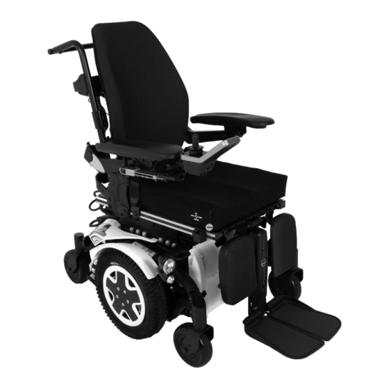
Service Component Notes Check Remedy Chair configuration Check chair Update software See LiNX service manual. configuration version if newer version available Check screws for tight Tighten screws if Screws (every 6 months) necessary 6.5 Overview mobility device Lifter This overview applies for TDX SP2 mobility devices with Modulite Seat. -
Page 22: Chassis
Invacare® TDX® SP2 Series 6.6 Chassis • 3/16 in Allen key • 5/16 in wrench with extension • 3/4 in wrench 6.6.1 Overview of Components • 5/32 in Allen key • 7/16 in socket wrench • Phillips screwdriver, size 2 •... - Page 23 Service 9. Remove batteries. See 6.11 Batteries, page 46. Invacare recommends always replacing both setting screws simultaneously to ensure that the mobility device works perfectly. Removing Setting Screw 1. Lift the mobility device up on one side and place a 14 cm high wooden block under the battery case so that the wheels are off the ground and can rotate freely.
-
Page 24: Top Walking Beam
Invacare® TDX® SP2 Series 1. Remove both protective caps of stability lock system. Fig. 6-11 They are held using a screw or a cable tie depending Rotate setting screw C until there is a space of on the mobility device’s date of manufacture. -
Page 25: Bottom Walking Beam
Service Removing Top Walking Beam 7. Note carefully how motor cable is routed. 8. If necessary, remove any existing cable ties which are 1. Remove batteries as described in 6.11.3 Making fixing motor cable. Batteries Accessible, page 46 and 6.11.4 Replacing 9. -
Page 26: Removing Rear Springs
Turn screws back by 1/8 turn. 6.6.7 Installing rear springs 6.6.6 Removing rear springs Invacare recommends always replacing both springs Invacare recommends always replacing both springs simultaneously to make sure that the mobility simultaneously to ensure that the mobility device device works perfectly. -
Page 27: Replacing Battery Tray
Service 1. Put springs G into position between suspension arm F and stop A. 2. Make sure rear springs are compressed: • Block method – Raise suspension arms and replace wooden blocks underneath them until springs are compressed. • Clamp method Remove two stop bolts A. -
Page 28: Replacing Rubber Stopper
Medium-strength thread locking adhesive function test with mobility device. (Loctite 243 or similar) 6.6.10 Replacing Rubber Stopper Removing Adapter Invacare recommends that you replace all rubber stoppers as soon as one needs replacing. • 5/16 inch wrench • 7/8 inch Allen key •... -
Page 29: Drive Components
Service 6.7.2 Replacing Motor/Gearbox Unit Replacing Tie-Down Bracket / Tilt-Module The seat can be set to two different seat heights. Adjust CAUTION! seat height at tie-down adapter according to following Risk of crushing table: The wheelchair is very heavy. Risk of injury to hands and feet. -
Page 30: Replacing Or Rotating Motor/Gearbox Unit Sealing
Invacare® TDX® SP2 Series Installing Motor/Gearbox Unit • 6 mm Allen key • 5/8“ Allen key 1. Replace defective components. • 7/8“ Allen key 2. Before installing a new motor/gearbox unit, make • 5/16“ Allen key sure sealing ring is correctly mounted. The sealing •... -
Page 31: Replacing Carbon Brushes
Service Removing carbon brushes 1. Turn off mobility device. 2. Remove drive wheels as described in 6.8.8 Replacing Drive Wheel (5–Screw Installation), page 38. Removing motor/gearbox clutch 3. Disengage motor (1) by setting engaging lever to "Push". 1. Removing motor/gearbox unit, as described in 6.7.2 In case of SSD motor, loosen nut (5), then Replacing Motor/Gearbox Unit, page 29. -
Page 32: Removing Rear Suspension
Invacare® TDX® SP2 Series 6.7.7 Removing rear suspension – alternative 9. Allow motors to cool down for 30 minutes. 10. Allow motors to run in reverse direction for an hour. method 11. Lift mobility device off wooden blocks. • More wooden blocks or joiner's clamps 6.7.6 Removing Rear Suspension... -
Page 33: Refitting Rear Suspension - Alternative Method
Service 3. Tighten screws to 60 Nm. 4. Install sockets and bolts you have removed. 4. Make sure that rear springs are compressed: 5. Tighten bolts to 60 Nm. • Block method – Lift suspension arm and place wooden blocks or similar underneath it until springs are pressed together and nylon spacer (2) can be fitted into recesses provided in suspension (6). -
Page 34: Adjusting Caster Fork
For the specifications of spare parts please see Technical Data, or consult the service manual, available from Invacare (in this connection please see the addresses and phone numbers at the end of this user manual). In case you require assistance, please contact your Invacare dealer. -
Page 35: Tyre Pressure
Puncture-proof tyres have no valves. There are five chapters about tyre repair and wheel For recommended tyre pressure see inscription on tyre, replacement: rim, or contact Invacare. Compare table below for conversion. • 6.8.8 Replacing Drive Wheel (5–Screw Installation), page 38 •... -
Page 36: Overview Of Power Wheelchair Models And Wheel Types
Invacare® TDX® SP2 Series Castor Wheels 6” 8” 9” 10” Wheel 18 Nm 18 Nm 16 Nm 16 Nm 25 Nm 25 Nm 18 Nm 100 Nm fixation — — — Rim halves 10 Nm 25 Nm 25 Nm 25 Nm 25 Nm 6.8.5 Overview of Power Wheelchair Models and Wheel Types... -
Page 37: Replacing Rim Inserts In Drive Wheels
Service Models Castor Wheels 6” 8” 9” 10” Single- Double-Sided Fork Double- Double- Single- Sided/ Sided Fork Sided Fork Sided Fork Double- Sided Fork TDX SP2 S4 Series Kite Bora Stream Mirage Dragon * For wheelchair-specific mounting instruction, see respective manual. 6.8.6 Replacing rim inserts in drive wheels 6.8.7 Replacing Tyres Repairing Pneumatic and Puncture-Protected Tyres... -
Page 38: Replacing Drive Wheel (5-Screw Installation)
Invacare® TDX® SP2 Series 12. Make sure that tyre is contacting wheel rim directly. WARNING! 13. Inflate tyre to prescribed pressure. Risk of Explosion 14. Make sure that tyre is still closely contacting wheel There is considerable pressure in the tyre. Risk rim. -
Page 39: Replacing Drive Wheel Hub
Service CAUTION! Risk of Uncontrolled Movement of Mobility Device – Turn off power supply (ON/OFF key). – Engage drive. – Before raising mobility device, secure wheels by blocking them with wedges. – Prevent the mobility device tipping by propping it up on a wooden block which is long and wide enough under the battery case. - Page 40 Invacare® TDX® SP2 Series Removing Wheel • 5 mm Allen key 1. Loosen and remove bolts A. • Oblong wooden block (at least 14 x 14 x 30 • 5 mm Allen key • 13 mm wrench • Oblong wooden...
-
Page 41: Replacing Castor Wheels On Single-Sided Fork
Service 4. Remove wheel (4). Installing Wheel 5. Replace any defective parts. 1. Install parts in reverse order. 2. When installing wheel, pay attention to correct Installing Wheel direction of rotation. 1. Install parts in reverse order. 3. Tighten screw (3). 2. -
Page 42: Removing Top Shroud
– Changes to drive program may only be carried out by trained providers. – Invacare can only give a warranty for safe mobility device driving behavior - especially tipping stability - for unaltered standard drive programs. -
Page 43: Replacing Tilt Actuator ("Fixed Pivot" Tilt)
Service Removing Power Module 1. Remove rear shroud. See 6.9 Shrouds, page 41. 2. Carefully note location of cable and connection locations of various plugs. Either mark each plug and socket, or take a photo with digital camera. 3. Unplug all plugs from power module. Fig. -
Page 44: Replacing Operating Hour Counter/Connecting
Invacare® TDX® SP2 Series 6.10.4 Replacing operating hour counter/connecting cable • 10 mm socket wrench The operating hour counter is located on rear shroud (2). Removing operating hours counter 1. Switch controls system of wheelchair off. 2. Remove rear shroud as described in chapter “Shrouds”. -
Page 45: Updating Software
Service 6.10.7 Checking cable 3. Position operating hour counter in cut-out. • 5/8“ Allen key • Size 2 Phillips screwdriver • Oblique pliers • Cable ties 5. Reposition retaining frame (6). 6. Place mounting bracket (2) on threaded rod (3) so that mounting bracket presses retaining frame on shroud. -
Page 46: Batteries
– Always wear protective goggles when handling batteries. Dead or damaged batteries can be given back to your provider or directly to Invacare. What to do if acid is discharged – Always take clothing which has been soiled by or dipped in acid off immediately! 6.11.3 Making Batteries Accessible... -
Page 47: Replacing Batteries (60 Ah / 73 Ah)
Service Removing Batteries 1. Make batteries accessible. See 6.11.3 Making Batteries Accessible, page 46. Fig. 6-35 Remove side-mounted legrests if fitted. A centre-mounted, manually adjustable legrest should be either put in its top position by turning the spindle A or removed. Elevate powered legrests to top position. Fig. -
Page 48: Replacing Batteries (50 Ah)
Invacare® TDX® SP2 Series 6.11.5 Replacing Batteries (50 Ah) • 3/8 in wrench • 19 mm wrench • Torque wrench 5 - 25 Nm (or similar) • Oblique pliers • Wooden block (approx. 30 x 40 x 29 cm) Removing Batteries Fig. -
Page 49: Checking And Replacing Main Fuse
Service 6.11.7 Checking and replacing main fuse CAUTION! Risk of fire An electric short can cause extremely high currents which can result in spark formation and fire – Always use an original strip fuse with the Pry open snap hook B with flat screwdriver C. approved amperage. -
Page 50: System)
Invacare® TDX® SP2 Series 6.12.2 Replacing headlight complete (conventional lighting system) • Phillips screwdriver size 2 • Oblique pliers • Cable ties Removing headlight In the illustration you can see lighting PCB B, power 1. Remove rear shroud as described in 6.9.2 Replacing module C and optional cross connector D. -
Page 51: Replacing Front Lamp Holder
Service 6.12.5 Replacing front lamp holder - 3. Remove lamp holder (4). 4. Moving lamp holder (3). (conventional lighting system) • Loosen two screws (1). • Phillips screwdriver • Move lamp holder (3) into position. • 4 mm Allen key •... -
Page 52: Replacing Complete Rear Light
Invacare® TDX® SP2 Series Open connector plug (3) for the rear light which needs to be replaced. 9. The rear lights are only clamped in by the plastic housing. If required, replace the red rear light (2) or the indicator (1). The cables are labelled appropriately. - Page 53 Service To retrofit a mobility device with a Dahl Docking system, it is imperative, that the mobility device Do not use any other screws than those is equipped with the correct adapter plate. This supplied from Dahl Engineering. Standard adapter plate must be threaded to fix the lock countersunk M8 screws are not strong plate of the Dahl Docking system underneath the enough in the event of a collision.
- Page 54 Notes...
- Page 55 Notes...
- Page 56 Invacare Sales Companies Australia: Canada: Ireland: New Zealand: Invacare Australia Pty. Ltd. Invacare Canada L.P. Invacare Ireland Ltd, Invacare New Zealand Ltd 1 Lenton Place, North Rocks NSW 570 Matheson Blvd East, Unit 8 Unit 5 Seatown Business Campus 4 Westfield Place, Mt Wellington 1060 2151 CDN Mississauga, On.
Need help?
Do you have a question about the TDX SP2 Series and is the answer not in the manual?
Questions and answers