Table of Contents
Advertisement
Step 1:
Unpack
Check the Contents
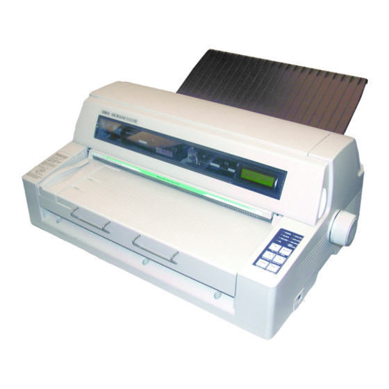
If any items are missing, contact your dealer
immediately.
1 Printer
2 Stacker
3 Power Cable
4 Ribbon Cartridge
Not illustrated: Documentation
®
OKI
MICROLINE
Setup Guide
Components Feb 17 06.jpg
®
8480FB
Space Requirements
Place the printer on a stable, level surface.
Check that sufficient space is available for the
installation:
• Width: 35.4" (90 cm)
• Depth
– Behind printer: 23.6" (60 cm)
– In front of printer: 12.6" (32 cm)
– Overall: 60.2" (153 cm)
• Height: 18" (46 cm) minimum
Environmental
Requirements
• Operating Temperature: 41 to 104°F (5 to 40°C)
• Humidity: 30 to 85% RH
Documentation
Your printer includes the following documentation:
• This Setup Guide
How to get the printer up and running.
• Safety and Regulatory Information booklet
Important safety information, along with general
regulatory information (FCC, Energy Star, IC, etc.)
and the Material Safety Data Sheet for the ribbon.
• User's Guide PDF file on the CD included with the
printer
Information on print modes, features such as Forms
Tear-Off and Auto Gap, setting the top of form,
using the control panel, making changes in the
printer defaults, clearing paper jams, etc.
Advertisement
Table of Contents

Related Manuals for Oki MICROLINE 8480FB


Summary of Contents for Oki MICROLINE 8480FB
-
Page 1: Space Requirements
® ® MICROLINE 8480FB Setup Guide Space Requirements Step 1: Place the printer on a stable, level surface. Unpack Check that sufficient space is available for the installation: • Width: 35.4" (90 cm) • Depth Check the Contents – Behind printer: 23.6" (60 cm) If any items are missing, contact your dealer –... -
Page 2: Printer Components
Printer Components Step 2: Front View Set Up the Printer Remove the Printhead Shipping Restraint 1. Open the cover using the grips on either side. F2_03_open_ cover.jpg F1_24a1.jpg 2. Peel the protective plastic film off the display 1 Ribbon Cartridge 7 Platen Knob panel. -
Page 3: Install The Power Cord
Install the Power Cord 4. Remove the shipping restraint ( 1. Make sure the printer power switch is in the OFF position: F2_04a.jpg F2_06.jpg 2. Attach the power cord to the back of the printer. F2_19.jpg Note Save the shipping restraint and packing materials in case you ever need to ship the printer. - Page 4 Warning! 5. Unpack the ribbon cartridge and remove the lock Make sure the printer is turned off before you pieces (1). open the cover. 3. Open the cover. F2_09.jpg F2_03_open_c over.jpg 6. Swing out the ribbon arms on either end of the cartridge until they snap into place.
- Page 5 8. Observe the black pin (1) over which the ribbon 10. Pull the ribbon out a bit at the left end of the knob fits, and the guides (2)—one at either end— cartridge to give some slack, then slide the ribbon into which the ribbon arms fit.
-
Page 6: Remove The Protective Film
Install the Stacker 13. Push the display panel back to its original position. With the flat edge toward the printer and the frosted side up, slide the stacker into the channels at either end of the support, pushing it in as far as it will go. F2_17_rev.jpg F2_15b.jpg 13. -
Page 7: Step 3: Run A Self Test
Step 3: Step 4: Run a Self Test Load Paper Before proceeding, run a self test to check that the Individual Sheets/Forms printer is operating correctly. This prints out a list of (“MANUAL”) available fonts. 1. Turn off the printer. The printer is set at the factory for •... -
Page 8: Switching Between Normal And High Impact Mode
Load Individual Sheets/Forms Individual Multi-Part Forms • Size 1. Pull out the sheet supports (1) and move the – Minimum Width: 3.9” (100 mm) sheet guide (2) to the right as far as it will go (the travel of the sheet guide is limited). –... -
Page 9: Continuous Forms ("Front")
Continuous Forms Load Continuous Forms (“FRONT”) 1. Push the sheet supports in and lift the sheet feed platform Continuous Forms Specifications • Width F5-03a.jpg – Minimum: 4” (102 mm) – Maximum: 16” (406 mm) • Single Thickness Forms –Weight range: 13.8 to 34 lb. US Bond (52 to 128 g/m •... -
Page 10: Removing Continuous Forms
4. Lift the lock lever (1) on the right tractor (2) and 8. Position the continuous forms stack below the move the tractor over to correspond to the width printer with no more than about 1 inch (3 cm) of the continuous forms you are using. Center the offset (1). -
Page 11: Step 5: Connect To The Computer
Parallel Port Step 5: Note Connect to the Computer No parallel cable is supplied with the printer. Use a shielded, bi-directional, IEEE-1284 compatible, parallel cable no longer than 6 ft. (1.2 m). 1. Turn off the printer. Caution! 2. Connect the parallel cable to the parallel port on Do not connect both the USB and parallel the printer and secure it with the wire loops. - Page 12 Oki Data Americas, Inc., 4140B Sladeview Crescent Unit 7 & 8 Mississauga, Ontario, Canada L5L 6A1 Télephone : 1-905-608-5000 Télécopier : 1-905-608-5040 www.okiprintingsolutions.com Oki Data de Mexico, S.A. de C.V., Mariano Escobedo #748 Piso 8, Col. Nueva Anzures, C.P. 11590, México, D.F. Tel: +52-555-263-8780 FAX: +52-555-250-3501 www.okiprintingsolutions.com Oki Data do Brasil Informática, Ltda., Rua Alfrefo Egidio de souza Aranha 100-4°, andr-Bloco C...
Need help?
Do you have a question about the MICROLINE 8480FB and is the answer not in the manual?
Questions and answers