
Subscribe to Our Youtube Channel
Related Manuals for Intelligent UFM-B


Summary of Contents for Intelligent UFM-B
- Page 1 A Higher Level of Precision… A Higher Level of Performance UFM-B UFM-F UFM-L NTEP Bench Scales Maintenance Manual...
-
Page 2: Table Of Contents
MAINTENANCE MANUAL UFM SERIES NTEP & MEASUREMENT CANADA CONTENTS 1. INTRODUCTION 2. SPECIFICATIONS 2.1 SYSTEM BLOCK DIAGRAM 2.2 PHYSICAL LAYOUT OF ELECTRICAL CONNECTION 2.3 GENERAL SPECIFICATIONS 2.4 INTERNAL SETTINGS AND CALIBRATION METHODS 3. TROUBLE SHOOTING 3.1 TROUBLE SHOOTING LOOP 3.2 PARTS AND COMPONENTS TROUBLE SHOOTING 4. -
Page 3: Introduction
1. INTRODUCTION The UFM series is designed and programmed according to NTEP and Measurement Canada requirements. These indicators are sealed to prevent unauthorized access to internal parts. End users should be advised not to undertake any trouble shooting except those listed in the operation manual. This maintenance manual contains of certain information that may result in fraudulent use. -
Page 4: Specifications
2. SPECIFICATION 2.1 SYSTEM BLOCK DIAGRAM LCD DRIVER INTERFACE with ROM A/D UNIT LOAD E- CELL S+ POWER SUPPLY: KEYBOARD AC ADAPTOR (6 KEYS) (9V/500mA) RECHARGEABLE BATTERY (6V 4Ah) Description: When a mass is placed on the platform, the load of the article is transferred to the load cell inside. -
Page 5: Physical Layout Of Electrical Connection
2.2 PHYSICAL LAYOUT OF ELECTRICAL CONNECTION LOAD CELL 5 PIN PLATFORM CONNECOTR RECHARGEABLE BATTERY 6V 4Ah INDICATOR RS-232 BOARD D-SUB 25 D-SUB 25 (FEMALE) RS232C-1B1 (FEMALE) RS232 PRINTER E+ E- S+ S- DC IN MAIN BOARD FM-12-X... - Page 6 2.2.1 CONNECTION BETWEEN INDICATOR AND PLATFORM(5 PIN ROUND CONNECTOR) PIN ASSIGNMENT INDICATOR PLATFORM EXC+ LOAD CELL PIN #1 SHIELD WHITE PIN #2 SIG+ SIG- GREEN PIN #3 BLACK PIN #4 PIN #5 EXC- 2.2.2 CONNECTION OF RS-232 BETWEEN INDICATOR AND PC(25PIN D-SUB) PIN ASSIGNMENT INDICATOR(25PIN D-SUB,FEMALE) PC(25PIN D-SUB,MALE)
- Page 7 2.2.3 Parallel Printer Interface (D-SUB 25 pin) PIN ASSIGNMENT PIN NUMBER ASSIGNMENT PIN NUMBER ASSIGNMENT STROBE BUSY...
-
Page 8: General Specifications
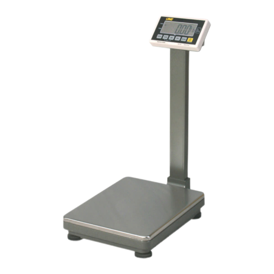
2.3 GENERAL SPECIFICATION 2.3.1 Overall View UFM SERIES Indicator Dimension UFM-B = 250(W) x 80 (D)mm x 150(H) UFM-F/L = 250(W) x 130(D)mm x 150(H) Overall Dimension UFM-B = 330(W) x 450(D) x 750(H)mm UFM-F = 420(W) x 520(D) x 880(H)mm... - Page 9 2.3.2 Model Specifications Model No. Capacity Readability Platform (Max) UFM-B30 30kg/60lb 0.01kg/0.02lb UFM-B60 60kg/120lb 0.02kg/0.05lb 330 x 450mm UFM-B150 150kg/300lb 0.05kg/0.1lb UFM-F60 60kg/120lb 0.01kg/0.02lb UFM-F120 120kg/250lb 0.02kg/0.05lb 420 x 520mm UFM-F300 300kg/600lb 0.05kg/0.1lb UFM-L60 60kg/120lb 0.01kg/0.02lb UFM-L120 120kg/250lb 0.02kg/0.05lb 500 x 600mm UFM-L300 300kg/600lb 0.05kg/0.1lb...
-
Page 10: Internal Settings And Calibration Methods
Power supply of 5 V DC; Minimum signal voltage per verification scale interval is 1.5 µV; 16 bits serial digital output; Excitation power supply for the load cell is 5 V DC; Minimum input impedance of the load cell is 85 Ω; Maximum cable length for the connection between the indicator and the junction box or load cells (when more then one load cell is connected) is 1 m/mm... - Page 11 2.4.3 Full Segment Display (F2) a. Refer to the 2.4.1 on how to enter F2 b. All display segments will light up c. Check all digits and arrow indications to verify any defects or errors d. Press TARE to quit 2.4.4 Span Value Reading/Configuration Setup (F3) The UFM series is designed according to NTEP and Measurement Canada requirements with maximum resolution legal for trade at 1/6000.
- Page 12 TO SET DECIMAL POINT a. Press M+ when display shows dP and select the decimal place from NIL to 3 decimal place b. Press MODE to save and continue setup TO SET CAPACITY AND GRADUATION (For Single interval, it means Max x e; for Dual Interval, it means Max a.
- Page 13 -To disable the AUTO POWER OFF function select “0-OFF” -To employ the AUTO POWER OFF function select “4-OFF” Press TARE to save and return to other function 2.4.6 RS-232 Transmission Setting (F5) a. Refer to the 2.4.1 on how to enter F5 b.
- Page 14 2.4.10 Auto Tare Function Setting (F9) a. Refer to the 2.4.1 on how to enter F9 b. Press MODE to select Troff or Tr_on -Troff will disable the auto tare off function -Tr_on will enable the auto tare function and tare off the first weight that is placed on the scale c.
- Page 15 2.4.14 CALIBRATION METHODS DEALER CALIBRATION a. Turn indicator off b. Press and hold TARE, then press ON/OFF c. Indicator displays F1 d. Press MODE to enter dealer calibration e. Press and hold MODE for YES and indicator will self calibrate zero point before proceeding to the first point calibration f.
- Page 16 NOTE: CALIBRATION IN LB When calibrating the scale in lb, please refer to the following steps: a. Enable the metric/imperial weighing unit conversion in F3 b. Press MODE to change the weighing unit to lb when scale is on c. Repeat the procedures in Auto Calibration...
-
Page 17: Trouble Shooting
3. TROUBLE SHOOTING 3.1 TROUBLE SHOOTING LOOP POWER ON DISPLAY RANDOM NO DISPLAY FIGURE COUNT DOWN? CHECK POWER SUPPLY, CHECK CPU,LCD, CPU,LCD,KEYBOARD LCD DRIVER IC SHOW “00000” COUNTS AND THEN ZERO? CHECK LOAD CELL, A/D UNIT,OFFSET VALUE GHOST UNSTABLE PROPER READOUT? CHECK PLATFORM CHECK POWER STOPS,LOAD... -
Page 18: Parts And Components Trouble Shooting
3.2 PARTS AND COMPONENTS TROUBLE SHOOTING 3.2.1 Power Supply Checks 3.2.1.1 Relevant parts: Main Board (FM-12-X) Q1 (A1515) Q2 (A733) U5 (IC 4027) U11(AIC 1722-5.0) Q5 (C1061) Q4 (C945) ZD1(ZENER 8.2V) R51(1.2R 1/2W) DC JACK BATTERY(6V 4Ah) Description: 1) Power source: Rechargeable Battery 6V/4Ah or AC adaptor(9V, 500mA) 2) +5V power drives digital circuit system. - Page 19 5) Low Power Detection: The Q2(A733) is designed to detect the power level. When battery power is less than 5.5V, the collector pole will become low potential, then CPU will instruct LCD display to show LO-BAT symbol. 3.2.1.2 Input voltage: 5.5V or higher Check and recharge battery if voltage is less than 5.5V.
- Page 20 When no error is found with the above checking procedures, the trouble can be caused by the loadcell or the PCB itself. Replace with a new one will help to identify the defective part. Following the replacement of any parts, it is important that the scale be recalibrated again.
-
Page 21: Electrical Circuitry
4. ELECTRICAL CIRCUITRY 4.1 SCHEMATICS... -
Page 24: Pcb Layout
4.2 PCB LAYOUT FM-12-1 TOP LAYER FM-12-1 BOTTOM LAYER... - Page 25 FM-12-1 TOP OVERLAY FM-12-1 BOTTOM OVERLAY...
-
Page 26: Bill Of Material
5. BILL OF MATERIAL STRUCTURE Parts No. Description Specification Remark__ UFM-B SERIES A1007000006 FERRITE CORE T-22.5*13.8*19.2mm A1007000004 FERRITE CORE T-28.3*13.8*13.5mm A1204040370 WIRE ARRAY 4 PIN 37cm C1W10000000 PANEL PC 200*78*2mm(TRANSPARENT) G0001NBS000 PLASTIC HOUSING(UNDER) NBS SERIES INDICATOR G0001FM0200 PLASTIC HOUSING(UPPER) FM SERIES (WHITE) - Page 27 UFM-F SERIES A0905600500 CONNECTOR 5 PIN(PLT-165-R) A1007000001 FERRITE CORE TR-16*9*28mm A1007000004 FERRITE CORE T-28.3*13.8*13.5mm A1204040370 WIRE ARRAY 4 PIN 37cm C1W10000000 PANEL PC 200*78*2mm(TRANSPARENT) F0005FW0100 ALUMINUM HOUSING (UNDER) FW SERIES INDICATOR G0001FM0200 PLASTIC HOUSING(UPPER) FM SERIES (WHITE) INDICATOR C1AFM030000 OVERLAY PC AFM SERIES E1FM0000012 P.C.B.
- Page 28 C1W10000000 PANEL PC 200*78*2mm(TRANSPARENT) F0005FW0100 ALUMINUM HOUSING (UNDER) FW SERIES INDICATOR G0001FM0200 PLASTIC HOUSING(UPPER) FM SERIES (WHITE) INDICATOR C1AFM030000 OVERLAY PC AFM SERIES E1FM0000012 P.C.B. KIT FM-12-X MAINBOARD A1600060400 RECHARGEABLE BATTERY 6V 4Ah A1208020351 BATTERY WIRE ARRAY 2PIN 35cm,SINGLE HOUSING A1208020601 BATTERY WIRE ARRAY 2PIN 60cm,SINGLE HOUSING...
- Page 29 A0300000040 I.C. SOCKET 40 PIN A0401007330 TRANSISTOR A733 Q2,5 A0401009450 TRANSISTOR 2SC945 A0401010610 TRANSISTOR H1061C OR D880 A0401015150 TRANSISTOR A1515 Q1,3 A0501004002 DIODE 1N4002 A0501004148 DIODE 1N4148 D1-4 A0502000001 BRIDGE RECTIFIER W06(1A) A0503020082 ZENER DIODE 1/2W 8V2(9A3) A0625050000 L.E.D. GREEN/RED,ROUND 5mm LED1 A0701106017 CAPACITOR (EC)
- Page 30 A1100211059 CRYSTAL 11.0592MHZ A1500000004 BUZZER OBO-15210 A1306000003 TACT SW. KPT-1104B SW1-6 A5004000004 HEAT SINK MB-217-22+PIN A/D SECTION A0203077050 I.C. AD7705AN A0206000072 OP177 U1-2 A0207029500 VOLTAGE REGULATOR I.C. AS2950AW A0702226016 CAPACITOR (TC) 22uF/16V(226) A0713105063 POLYESTER FILM CAPACITOR(MEF) 1uF/63V (105) A0730104050 CAPACITOR (MLC) 104Z C1-6,C8-9,C16-17 A0740047050...
- Page 31 RS232 OPTION A0901010040 CONNECTOR 4 PIN WAFER E1HBW100000 P.C.B. KIT HBW SERIES, RS232C-1B1...
-
Page 32: Appendix
5. APPENDIX... - Page 40 REV. APPROVED NO. DRAWING NO.: UFM-M-01-A DWG. UFM-B SERIES NAME SEALING DIAGRAM UFM-B SERIES SEALING DIAGRAM SEALING POSITION...
- Page 41 REV. APPROVED NO. DRAWING NO.: UFM-M-02-A DWG. UFM-F/L SERIES NAME SEALING DIAGRAM UFM-F/L SERIES SEALING DIAGRAM SEALING POSITION...
- Page 42 ITEM QTY PART NO. PART NAME DESCRIPTION REMARK F0002BS0000 STAINLESS STEEL PLATTER BS SERIES 460*335*17 F0100NBS000 ALUMINUM UPPER CABINET NBS(FOUR HOLES) A0045040*** LOAD CELL 042-XXXkg F0100NBS000 ALUMINUM UNDER CABINET NBS(FOUR HOLES) G0004NBS000 ADJUSTABLE FEET Z0014000625 SCREW M6*1P*25L, HEX SOCKET Z0040001006 WASHER M6 OR 1/4"...
- Page 43 ITEM QTY PART NO. PART NAME DESCRIPTION REMARK F0002FW0000 S/S PLATTER FW SERIES, 400*500 F0100FW0001 ALUMINUM PLATFORM SET FW SERIES UPPER A0004600*** LOAD CELL 263-XXXkg F0100FW0001 ALUMINUM PLATFORM SET FW SERIES UNDER G0004FW0000 ADJUSTABLE FEET FW SERIES Z0016000012 M12*1.75P Z0014000830 SCREW M8*1.25P*30L Z0040001005...
Need help?
Do you have a question about the UFM-B and is the answer not in the manual?
Questions and answers