Table of Contents
Advertisement
Advertisement
Table of Contents
Troubleshooting

Related Manuals for Razorweld KUMJRRW145


Summary of Contents for Razorweld KUMJRRW145
- Page 1 Razorweld ® ™ ™ OPERATING MANUAL KUMJRRW145 KUMJRRW180 KUMJRRW210 YEARS Warranty (Power Source) Please read and understand this instruction manual carefully before the installation and operation of this equipment. © JASIC Technologies America Inc 2013...
-
Page 2: Warranty
• Product will only be replaced if repair is not possible • Please view full Warranty term and conditions supplied with machine or at www.razorweld.com or at the back of this manual. -
Page 3: Table Of Contents
CONTENTS PAGE Warranty Technical Data, Product Information Safety - Cautions Machine Layout Installation & Operation for ARC(stick) Welding ARC (Stick) Welding Information 12-13 Installation & Operation for MIG Welding with Gas 14-15 Wire Feed Drive Roller Selection Wire Installation Set up Guide Installation &... -
Page 4: Technical Data, Product Information
Weight Machine (Ibs.) This new RAZORWELD Welder will provide 145 amps of MIG, TIG and ARC output for you to complete your welding jobs! Ideal for the DIY enthusiast ,this beautifully designed and highly functional multi-system is a powerful, portable and dual voltage machine ensuring smooth and trouble free welding and backed up by a big 3 year warranty. - Page 5 28.4 Pounds (Machine) This new RAZORWELD Welder will provide 180 amps of MIG, TIG and ARC output for you to complete your welding jobs! Ideal for the serious tradesman ,this beautifully designed and highly functional multi-system is a powerful, portable and dual voltage machine ensuring smooth and trouble free welding and backed up by a big 3 year warranty.
- Page 6 28.4 Pounds (Machine) This new RAZORWELD Welder will provide 210 amps of MIG, TIG and ARC output for you to complete your welding jobs! Ideal for the serious tradesman ,this beautifully designed and highly functional multi-system is a powerful, portable and dual voltage machine ensuring smooth and trouble free welding and backed up by a big 3 year warranty.
-
Page 7: Safety - Cautions
SAFETY Welding and cutting equipment can be dangerous to both the operator and people in or near the surrounding working area, if the equipment is not correctly operated. Equipment must only be used under the strict and comprehensive observance of all relevant safety regulations. Read and understand this instruction manual carefully before the installation and operation of this equipment. - Page 8 Fire hazard. Welding on closed containers, such as tanks,drums, or pipes, can cause them to explode. Flying sparks from the welding arc, hot work piece, and hot equipment can cause fires and burns. Accidental contact of electrode to metal objects can cause sparks, explosion, overheating, or fire.
-
Page 9: Working Environment
CAUTION 1. Working Environment. 1.1 The environment in which this welding equipment is installed must be free of grinding dust, corrosive chemicals, flammable gas or materials etc, and at no more than maximum of 80% humidity. 1.2 When using the machine outdoors protect the machine from direct sun light, rain water and snow etc; the temperature of working environment should be maintained within 14°Fto .4 to +104°F. -
Page 10: Machine Layout
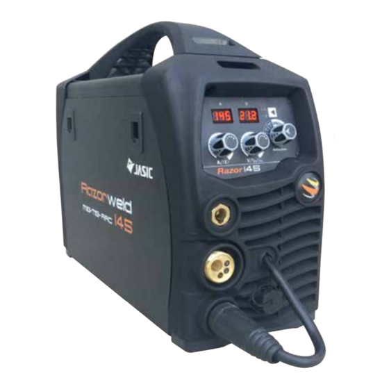
FRONT PANEL LAYOUT 1. Digital Volts Meter 2. Digital Amps Meter 3. 2T/4T Selector Button 4. Wire Speed / AmpsAdjustment Knob 5. Voltage / Downslope /ARC Force Adjustment Knob 6. MIG / TIG / MMA /Smartset Selector Knob 7. “-” Output terminal 8. -
Page 11: Installation & Operation For Arc(Stick) Welding
Installation set up for ARC (Stick) Welding with RAZOR 210 Connection of Output Cables Two sockets are available on this welding machine. For ARC welding the electrode holder is shown be connected to the negative socket, while the earth lead (work piece) is connected to the positive socket, this is known as DC- polarity. -
Page 12: Arc (Stick) Welding Information
ARC Welding One of the most common types of arc welding is manual metal arc welding (MMA) or stick welding. An electric cur- rent is used to strike an arc between the base material and a consumable electrode rod or ‘stick’. The electrode rod is made of a material that is compatible with the base material being welded and is covered with a flux that gives off gaseous vapours that serve as a shielding gas and providing a layer of slag, both of which protect the weld area from atmospheric contamination. - Page 13 ARC Welding Fundamentals Electrode Selection As a general rule, the selection of an electrode is straight forward,in that it is only a matter of selecting an electrode of similar composition to the parent metal. However, for some metals there is a choice of several electrodes, each of which has particular properties to suit specific classes of work.
-
Page 14: Installation & Operation For Mig Welding With Gas
• When 4T operation is selected press and release trigger Arc starts, press and release trigger Arc stops. burnback operation is automatic and preset. SmartSet by RazorWeld ® makes welding easy by taking the guess work out of MIG machine settings.Simply select the correct wire diameter and gas type that you’re using then dial in your desired wire feed speed for the job. - Page 15 Continued set up for MIG with Gas for RAZOR 210 (7) Place wire onto spool holder - (spool retaining nut is left hand thread ) Feed the wire through the inlet guide tube on to the drive roller. (8) Feed wire over the drive roller into the outlet guide tube, Push the wire through approx 3-4in (9) Align the wire into the groove of the drive roller and close down the top roller making sure the wire is in the groove of the bottom drive roller, lock the pressure arm into place.
-
Page 16: Wire Feed Drive Roller Selection
Wire Feed Roller Selection The importance of smooth consistent wire feeding during MIG welding cannot be emphasized enough. Simply put the smoother the wire feed then the better the welding will be. Feed rollers or drive rollers are used to feed the wire mechanically along the length of the welding gun. Feed rollers are designed to be used for certain types of welding wire and they have different types of grooves machined in them to accommodate the different types of wire. -
Page 17: Wire Installation Set Up Guide
Wire Installation and Set Up Guide Again the importance of smooth consistent wire feeding during MIG welding cannot be emphasized enough. The correct installation of the wire spool and the wire into the wire feed unit is critical to achieving an even and consistent wire feed. -
Page 18: Installation & Operation For Mig Welding With No Gas
Installation set up for MIG with Gasless for RAZOR 210 (1) Connect Mig Torch IMPORTANT : When connecting the torch be sure to tighten the connection. Additionally Digital MIG torch must be connected prior to power being turned on otherwise remote control will not work (2) Connect the earth lead to Positive socket (3) Connect the weld power lead to Negative socket (4) Turn the power source on and select the MIG function with the MIG/TIG/MMA selector switch. - Page 19 Continued set up for MIG with Gasless wire for RAZOR 210 (7) Place the Wire Spool onto the Spool Holder - Note: the spool retaining nut is Left Hand thread. Snip the wire from the spool being sure to hold the wire to prevent rapid uncoiling. Feed the wire into the wire feeder inlet guide tube through to the drive roller.
-
Page 20: Installation Guide For Mig Torch Liner Installation
Mig Torch Liner Installation (1) Lay the torch out straight on the ground and remove the front end parts (2) Remove the liner retaining nut. (3) Carefully pull the liner out of the torch cable assembly (4) Select the correct new liner and carefully unravel avoiding putting any kinks in the liner, if you kink the liner it will make it no good and will require replacement. -
Page 21: Mig Torch And Wire Feeder Set Up Guide For Aluminum Mig Wire
Torch & Wire Feed Set Up for Aluminium Wire (1) Lay the torch out straight on the ground and remove the front end parts (2) Remove the liner retaining nut. (3) Carefully pull the liner out of the torch cable assembly (4) Select a PA or liner, carefully and slowly feed the liner in short forward movements down the cable assembly all the way through and out the torch neck end. - Page 22 Continued Torch & Wire Feed Set Up for Aluminum Wire (10) Loosen off the inlet guide tube retaining screw (11) Remove the inlet guide tube from the front end machine euro connector using long nose pliers. (12) Carefully feed the extended PA liner section into the inlet guide tube hole of the machine euro connector (13) Feed the extended PA liner all the way up and over the drive roller (14) Tighten the torch euro connection to the machine euro connector...
-
Page 23: Installation & Operation For Mig Welding With Spool Gun
Installation set up of the Spool Gun for RAZOR 210 Select Spool Gun using the Standard/Spool Gun selector switch. Connect the Spool Gun to the Euro MIG torch connection socket on the front panel, and tighten it. Connect the Spool Gun control cable to the receptacle and tighten it. When connecting the torch be sure to tighten the connection. - Page 24 Continued set up of the Spool Gun with RAZOR 210 Carefully feed the wire over the drive roller into the outlet guide tube, feed through into the torch neck. Check that the drive roller being used complies with the wire diameter, replace the roller if necessary. (10) Align the wire into the groove of the drive roller and release the tension arm making sure the wire is in the groove of the drive roller.
-
Page 25: Mig (Metal Inert Gas) Welding
MIG (Metal Inert Gas) Welding Definition of MIG Welding MIG (metal inert gas) welding also known as GMAW (gas metal arc welding) or MAG (metal active gas welding), is a semi-automatic or automatic arc welding process in which a continuous and consumable wire electrode and a shielding gas are fed through a weld- ing gun. - Page 26 MIG (Metal Inert Gas) Welding Short Circuit Transfer - Short circuit transfer is the most common used method whereby the wire electrode is fed continuously down the welding torch through to and exiting the contact tip. The wire touches the work piece and causes a short circuit the wire heats up and begins to form a molten bead, the bead separates from the end of the wire and forms a droplet that is transferred into the weld pool.
-
Page 27: Basic Mig Welding Guide
Basic MIG Welding Good weld quality and weld profile depends on gun angle, direction of travel, electrode extension (stick out), travel speed, thickness of base metal, wire feed speed (amperage) and arc voltage. To follow are some basic guides to assist with your setup. Gun Position - Travel Direction, Work Angle Gun position or technique usually refers to how the wire is directed at the base metal, the angle and travel direction chosen. - Page 28 Travel Angle - Travel angle is the right to left angle relative to the direction of welding. A travel angle of 5°- 15° is ideal and produces a good level of control over the weld pool. A travel angle greater that 20° will give an unstable arc condition with poor weld metal transfer, less penetration, high levels of spatter, poor gas shield and poor quality finished weld.
- Page 29 Travel Speed - Travel speed is the rate that the gun is moved along the weld joint and is usually measured in mm per minute. Travel speeds can vary depending on conditions and the welders skill and is limited to the welders ability to control the weld pool. Push technique allows faster travel speeds than Drag technique.
- Page 30 Wire types and sizes - Use the correct wire type for the base metal being welded. Use stainless steel wire for stainless steel, aluminium wires for aluminium and steel wires for steel. Use a smaller diameter wire for thin base metals. For thicker materials use a larger wire diameter and larger machine, check the recommended welding capability of you machine.
-
Page 31: Installation & Operation For Tig Welding
RAZOR 210 Installation and set up for DC TIG welding for (1) Connect TIG torch to Euro connection socket, IMPORTANT : When connecting the torch be sure to tighten the connection. (2) Connect earth lead to Positive (3) Connect weld power lead to Negative (4) Turn the power source on and select the TIG function with the MIG/TIG/MMA selector switch. - Page 32 LIFT ARC DC TIG Operation for RAZOR 210 Lift Arc ignition allows the arc to be started easily in DC TIG by simply touching the tungsten to the work piece and lifting it up to start the arc. This prevents the tungsten tip sticking to the work piece and breaking the tip from the tungsten electrode.
-
Page 33: Tig Fusion Technique
TIG Welding Fusion Technique Manual TIG welding is often considered the most difficult of all the welding processes. Because the welder must maintain a short arc length, great care and skill are required to prevent contact between the electrode and the workpiece. Similar to Oxygen Acety- lene torch welding, Tig welding normally requires two hands and in most instances requires the welder to manually feed a filler wire into the weld pool with one hand while manipulating the welding torch in the other. -
Page 34: Tungsten Electrodes & Preparation
Tungsten Electrodes Tungsten is a rare metallic element used for manufacturing TIG welding electrodes. The TIG process relies on tung- sten’s hardness and high-temperature resistance to carry the welding current to the arc. Tungsten has the highest melting point of any metal, 3,410 degrees Celsius. Tungsten electrodes are nonconsumable and come in a variety of sizes, they are made from pure tungsten or an al- loy of tungsten and other rare earth elements. -
Page 35: Tungsten Preparation
Tungsten Preparation Always use wheels when grinding and cutting. While tungsten is a very hard material, the surface of a DIAMOND diamond wheel is harder, and this makes for smooth grinding. Grinding without diamond wheels, such as aluminium oxide wheels, can lead to jagged edges, imperfections, or poor surface finishes not visible to the eye that will contrib- ute to weld inconsistency and weld defects. -
Page 36: Twc2 Mig Torch Parts Breakdown
TWC2 STYLE MIG TORCH TWC2 STYLE MIG TORCH TWC2 Air Cooled Mig Welding Torch TWC2 STYLE MIG TORCH Rating: 200A CO2 150A mixed gas, EN60974-7 @ 60% duty cycle. TWC2 Air Cooled Mig Welding Torch TWC2 Air Cooled Mig Welding Torch 0.6 to 1.2mm / 0.025”... -
Page 37: Spare Parts
Spare Parts for Tweco 2 style torches Torch Model Description Part Number EAN CODE 15 FT Welding Torch Classic Style TWC2-15FTE 0680474943777 10 FT Welding Torch Euro Style Handle TWC2-10FTE 0680474944095 TWC2 Contact Tips Part Number Description EAN CODE PRW14-30 Contact tip 0.8mm / 0.030”... - Page 38 SPG200II AMP SPOOL GUN Duty Cycle 35% @ 200Amp Wear Parts Next Page Torch Model Description Part Number Spool Gun x 19ft SPGRWA200 Spare Parts Part Number Description Part Number Description LMZ2017 Speed Adjusting Knob LMZ2014 Potentiometer LMH2114 Open/Close Button LMZ2015 Push Roll LMH2111...
- Page 39 SPG200II AMP SPOOL GUN TWC2 Contact Tips Part Number Description EAN CODE PRW14-30 Contact tip 0.8mm / 0.030” QTY x5 0680474943920 PRW14-35 Contact tip 0.9mm / 0.035” QTY x5 0680474943937 PRW14-40 Contact tip 1.0mm / 0.040” QTY x5 0680474944033 PRW14-45 Contact tip 1.2mm / 0.045”...
-
Page 40: Sre Tig Torch Parts Breakdown
SR17 EURO TIG TORCH 150A AIR COOLED TIG WELDING TORCH Rating: 150A DC, 105A AC @35% ducy cycle. Wear Parts Identification Next Page Torch Model Description Part Number 13ft SR17 Suregrip Tig Torch Package Euro Connection SRE17-13FTE Spare Parts Part Number Description Part Number Description... - Page 41 Standard Front End Parts SR17 EURO TIG TORCH Part # Description Part # Description Part # Description 18CG Cup Gasket 10N30 Collet Body 1.0mm / 0.040” 10N49L Long Alumina Nozzle Ø 8mm / (5/16) 10N31 Collet Body 1.6mm / (1/16) 53N48L Long Alumina Nozzle Ø...
-
Page 42: Mma Welding Trouble Shooting Guide
ARC(Stick) WELDING TROUBLE SHOOTING The following chart addresses some of the common problems of MMA welding. In all cases of equipment malfunction, the manufacturer’s recommendations should be strictly adhered to and followed. 1: No arc Possible Reason Suggested Remedy Incomplete welding circuit Check earth lead is connected. -
Page 43: Mig Welding Trouble Shooting Guide
MIG WELDING TROUBLE SHOOTING The following chart addresses some of the common problems of MIG welding. In all cases of equipment malfunction, the manu- facturer’s recommendations should be strictly adhered to and followed. 1: Excessive Spatter Possible Reason Suggested Remedy Wire feed speed set too high Select lower wire feed speed Voltage too high... - Page 44 MIG WIRE FEED TROUBLE SHOOTING The following chart addresses some of the common WIRE FEED problems during MIG welding. In all cases of equipment malfunction, the manufacturer’s recommendations should be strictly adhered to and followed. 1: No wire feed Possible Reason Suggested Remedy Wrong mode selected Check that the TIG/ARC/MIG selector switch set to MIG position...
-
Page 45: Tig Welding Trouble Shooting Guide
TIG WELDING TROUBLE SHOOTING The following chart addresses some of the common problems of DC TIG welding. In all cases of equipment malfunction, the manufacturer’s recommendations should be strictly adhered to and followed. 1: Tungsten burning away quickly Possible Reason Suggested Remedy Incorrect Gas Check that pure Argon is being used... - Page 46 continued- TIG WELDING TROUBLE SHOOTING 8: Arc difficult to start or will not start DC welding Possible Reason Suggested Remedy Incorrect machine set up Check machine set up is correct No gas, incorrect gas flow Check the gas is connected and cylinder valve open, check hoses, gas valve and torch are not restricted.
-
Page 47: Warranty
JASIC Technologies America Inc (‘Us’, ‘We’) warrants that the following products under RAZORWELD supplied by Us and purchased by you from an Authorised RAZORWELD Dealer throughout the U.S.A & Canada are free of Material and Faulty Workmanship defects except for those products listed under ‘Warranty Exclusions’. - Page 48 WARRANTY / RETURNS / EXCHANGES We understand that sometimes a product may need to be returned. If you have purchased from the RAZORWELD Authorised Dealer Network, to assist you in following the correct procedure enclosed is the returns policy. Our Returns Policy includes the rights you have under the American consumer Law and other relevant laws.
- Page 49 Failure or any breakage caused by overload, dropping or abusive treatment or use by the customer • Repair, modifications or other work carried out on the product other than by an Authorised RAZORWELD Dealers Unless it is a manufacturing fault, this Warranty does not cover the following parts:...
- Page 52 © JASIC Technologies America Inc 2013 EST. 1985 Razorweld ® JASIC Technologies America Inc 25503 74th Ave S Kent WA 98032 USA Phone: +1 253-859-6277 +1 253-859-6278 FAX: +1 253-859-6286 EMAIL: sales@jasictechamerica.com sales@razorweld.com Part of the JASIC group of companies...
Need help?
Do you have a question about the KUMJRRW145 and is the answer not in the manual?
Questions and answers