
Related Manuals for Razorweld Xcel-Arc MULTI 230 AC/DC


Summary of Contents for Razorweld Xcel-Arc MULTI 230 AC/DC
- Page 1 MULTI 230 AC/DC XA-MIG230RZMTS | Operating Manual YEAR M ACH I NE Please read and understand this instruction manual carefully WARRANTY before the installation and operation of this equipment. © Xcel-Arc 2023...
-
Page 3: Table Of Contents
CONTENTS GENERAL INFORMATION SAFETY TECHNICAL DATA MACHINE LAYOUT WHAT’S IN THE BOX DIGITAL SCREEN OPERATION DIGITAL SCREEN - BASIC OPERATION DIGITAL SCREEN - SETTINGS MENU DIGITAL SCREEN - MMA (STICK) DIGITAL SCREEN - MIG DIGITAL SCREEN - MIG SMART-SET DIGITAL SCREEN - TIG MIG SETUP SETUP FOR MIG (GASLESS) SETUP FOR MIG (GAS-SHIELDED) -
Page 4: Safety
SAFETY Welding and cutting equipment can be dangerous to both the operator and people in or near the surrounding working area if the equipment is not correctly operated. Equipment must only be used under the strict and comprehensive observance of all relevant safety regulations. Read and understand this instruction manual carefully before the installation and operation of this equipment. - Page 5 SAFETY Fire hazard. Welding/cutting on closed containers, such as tanks, drums, or pipes, can cause them to explode. Flying sparks from the welding/cutting arc, hot workpiece, and hot equipment can cause fires and burns. Accidental contact of the electrode to metal objects can cause sparks, explosion, overheating, or fire. Check and be sure the area is safe before doing any welding/cutting.
- Page 6 SAFETY CAUTION 1. Working Environment. The environment in which this welding/cutting equipment is installed must be free of grinding dust, corrosive chemicals, flammable gas or materials etc., and at no more than a maximum of 80% humidity. ii. When using the machine outdoors, protect the machine from direct sunlight, rainwater and snow, etc.; the temperature of the working environment should be maintained within -10°C to +40°C.
- Page 7 SAFETY ATTENTION! - CHECK FOR GAS LEAKAGE At initial set up and at regular intervals we recommend to check for gas leakage Recommended procedure is as follows: 1. Connect the regulator and gas hose assembly and tighten all connectors and clamps. 2.
-
Page 8: Technical Data
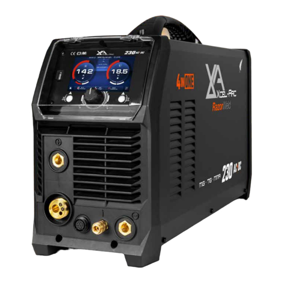
TECHNICAL DATA RAZOR MULTI 230 AC/DC MIG/TIG/STICK Welder Key Features: • 4-in-1 Multi-process • AC/DC High-Frequency TIG • 5″ Colour LCD • Synergic Programs • Geared Wire Drive • Power Factor Correction TECHNICAL DATA TIG SPECIFICATIONS SKU XA-MIG230RZMTS TIG FUNCTION TYPE AC/DC High-Frequency PRIMARY INPUT VOLTAGE 230V Single Phase TIG WELDING CURRENT RANGE 10-200A SUPPLY PLUG 15 AMP... -
Page 9: Machine Layout
MACHINE LAYOUT Front Panel Layout 1. Digital Screen 2. USB Port 3. Left Action Button 4. Selector / Scroll Knob 5. Right Action Button 6. "+" Output Terminal 7. Euro Connection 8. 12 Pin Socket 9. Gas Outlet 10. "-" Output Terminal Rear Panel Layout 11. -
Page 10: What's In The Box
4m 300 AMP Earth Clamp Twin Gauge Argon Regulator Drive Rollers MULTI 230 AC/DC XA-MIG230RZMTS | Operating Manual RazorWeld YEAR M ACHI NE Please read and understand this instruction manual carefully WARRANTY before the installation and operation of this equipment. -
Page 11: Digital Screen - Basic Operation
DIGITAL SCREEN - BASIC OPERATION 1. Main Control Knob rotate Turn this knob for digital screen navigation and cycling through menu options. If a menu item is active, turning this knob will adjust the menu item value. hand-bac Press this knob in order to confirm actions, between the weld screen and the weld menu parameters. -
Page 12: Digital Screen - Settings Menu
DIGITAL SCREEN - SETTINGS MENU Select the Settings menu from the Home Screen. Press the Right Action Button to cycle between the General Settings and Machine Settings menus. General Settings Machine Settings 1. Languages 7. Fan Choose desired language from this menu. Change fan between Normal and Smart modes. -
Page 13: Digital Screen - Mma (Stick)
DIGITAL SCREEN - MMA (STICK) 1. MMA Settings 2. Advanced MMA Settings 3. Button Functions 1. MMA Settings Current ii. Pulse Turn Pulse Off or On. Pulse MMA (STICK) welding helps reduce spatter, improves heat control and allows for an easier removal of slag. It also improves the speed and efficiency of vertical up welds by eliminating the use of the “Christmas Tree”... -
Page 14: Digital Screen - Mig
DIGITAL SCREEN - MIG 1. Standard MIG Settings 2. Advanced MIG Settings 3. Button Functions 1. Standard MIG Settings Wire Speed ii. Voltage iii. Torch Trigger Select the desired Torch Trigger. Torch Cycle Description 2T (two touch) means you will need to hold the trigger down on your MIG torch while you weld. -
Page 15: Digital Screen - Mig Smart-Set
DIGITAL SCREEN - MIG SMART-SET 1. MIG Smart-Set Setup 2. Standard MIG Settings 3. Advanced MIG Settings 4. Button Functions 1. MIG Smart-Set Setup Joint Type Select the desired joint type. • Butt Joint • Lap Joint • Fillet Joint ii. - Page 16 DIGITAL SCREEN - MIG SMART-SET 3. Advanced MIG Settings 2T/4T/SPOT Setting Values Description Pre Flow 0-20s Set how long you would like your gas to flow before the arc ignites. Slow Feed 0-10 Set the amount of Creep Start to allow for smoother arc ignition when welding at higher welding speeds. Welding Amp Set the peak welding current.
-
Page 17: Digital Screen - Tig
DIGITAL SCREEN - TIG 1. TIG Smart-Set Setup 2. Standard TIG Settings 3. Advanced TIG Settings 4. Button Functions 1. TIG Smart-Set Setup Material Type ii. Joint Type Select the desired material. Select the desired joint type. • Mild Steel •... - Page 18 DIGITAL SCREEN - TIG 3. Advanced TIG Settings Setting Values Description Pre-flow 0-20s Set how long you would like your gas to flow before the arc ignites. Start Amp 10-200A Set the starting current when the arc ignites. Up Slope 0-20s Set how long it takes for the Start Amp to reach the Peak Amp.
- Page 19 DIGITAL SCREEN - TIG DC Spot Setting Values Description Pre-flow 0-20s Set how long you would like your gas to flow before the arc ignites. Peak Amp 10-200A Set the peak welding current. Down Slope 0-20s Set how long it takes for the Peak Amp to reach the End Amp. End Amp 10-200A Set the End Amp to adjust how hot your weld will finish.
-
Page 20: Setup For Mig (Gasless)
SETUP FOR MIG (GASLESS) Connect the polarity connector to the negative (-) Connect the earth clamp to the positive (+) connection, unscrew the bolt and move the dinse connection, twist to lock in place. connector, then screw and tighten in place. Connect the MIG torch to the Euro connection Connect the plug into a 15 AMP socket, then and twist end to secure in place. - Page 21 SETUP FOR MIG (GASLESS) Pull down the roller tension knob to release the Unscrew both roller caps. wire drive. Ensure you have Knurled (F Groove) drive Unscrew spool retaining nut. rollers installed. If not, fit correct rollers and replace the roller covers. Burnback Adjustment...
- Page 22 SETUP FOR MIG (GASLESS) Place 5kg wire spool onto the spool holder. For Tighten spool retaining nut. 1kg spool, see step 19. STANDARD STANDARD SPOOL GUN SPOOL GUN Burnback Adjustment Burnback Adjustment Burnback Adjustment Burnback Adjustment Feed wire through the inlet guide tube through Lift roller tension knob to lock wire in place.
- Page 23 SETUP FOR MIG (GASLESS) Remove front end consumables from the MIG To initiate the wire inching, go to the screen torch. below as your desired MIG mode.Then press and hold the Right Action button to feed wire through to the torch. Once it's fed, Hold the torch trigger to feed Replace front end consumables on the MIG more if needed.
- Page 24 SETUP FOR MIG (GASLESS) Line up the torch with your workpiece, then simply pull the trigger to initiate the weld. For gasless MIG, the drag method is recommended for optimum weld quality. Release trigger to end the weld.
-
Page 25: Setup For Mig (Gas-Shielded)
SETUP FOR MIG (GAS-SHIELDED) Connect the polarity connector to the positive (+) Connect the earth clamp to the negative (-) connection, unscrew the bolt and move the dinse connection, twist to lock in place. connector then screw and tighten in place. Connect the MIG torch to the Euro connection Connect the plug into a 15 AMP socket, then and twist end to secure in place. - Page 26 SETUP FOR MIG (GAS-SHIELDED) Pull down the roller tension knob to release the Unscrew both roller caps. wire drive. Ensure you have V Groove drive rollers Unscrew the roller cap. installed. If not, fit correct rollers and replace the roller covers. Burnback Adjustment Burnback Adjustment...
- Page 27 SETUP FOR MIG (GAS-SHIELDED) Place 5kg wire spool onto the spool holder. For Tighten spool retaining nut. 1kg spool, see step 24. STANDARD STANDARD SPOOL GUN SPOOL GUN Burnback Adjustment Burnback Adjustment Burnback Adjustment Burnback Adjustment Feed wire through the inlet guide tube through Lift roller tension knob to lock wire in place.
- Page 28 SETUP FOR MIG (GAS-SHIELDED) To initiate the wire inching, go to the screen Remove front end consumables from the MIG below as your desired MIG mode. Then press torch. and hold the Right Action button to feed wire through to the torch. Once it's fed, Hold the torch trigger to feed Replace front end consumables on the MIG more if needed.
- Page 29 SETUP FOR MIG (GAS-SHIELDED) Connect gas hose to the regulator outlet, and Adjust gas flow to 8-12L/min. crimp in place. C E L - Connect gas hose to the gas inlet on the rear Connect earth clamp to your workpiece. of the machine.
- Page 30 SETUP FOR MIG (GAS-SHIELDED) Set weld paramaters on the digital screen. Line up the torch with your workpiece, then See "Digital Screen - MIG/MIG SMART-SET" on simply pull the trigger to initiate the weld. pages 14-16. For gas-shielded MIG, the push method is recommended for optimum weld quality.
-
Page 31: Mig Welding Guide
MIG WELDING GUIDE MIG (Metal Inert Gas) Welding MIG (Metal Inert Gas) welding, also known as GMAW (Gas Metal Arc Welding) or MAG (Metal Active Gas Welding), is a semi-automatic arc welding process in which a consumable wire electrode and a shielding gas are fed through a welding gun. - Page 32 MIG WELDING GUIDE Basic MIG Welding Good weld quality and weld profile depend on gun angle, the direction of travel, electrode extension (stick out), travel speed, the thickness of base metal, wire feed speed (amperage) and arc voltage. To follow are some basic guides to assist with your setup.
- Page 33 MIG WELDING GUIDE Travel Angle The travel angle is the right to left, relative to the direction of welding. A travel angle of 5°- 15° is ideal and produces the right level of control over the weld pool. A travel angle higher than 20° will give an unstable arc condition with poor weld metal transfer, less penetration, high levels of spatter, weak gas shielding and a poor quality finished weld.
- Page 34 MIG WELDING GUIDE Travel Speed Travel speed is the rate that the gun is moved along the weld joint and is usually measured in mm per minute. Travel speeds can vary depending on conditions and the welder's skill and is limited to the welder's ability to control the weld pool.
- Page 35 MIG WELDING GUIDE Wire Types and Sizes Use the correct wire type for the base metal being welded. Use stainless steel wire for stainless steel, Drive Rollers aluminium wires for aluminium and steel wires for steel. 1. Main Control Knob i.
-
Page 36: Setup For Spool Gun
SETUP FOR SPOOL GUN Connect the polarity connector to the positive (+) Connect the earth clamp to the negative (-) connection, unscrew the bolt and move the dinse connection, twist to lock in place. connector then screw and tighten in place. Connect the Spool Gun to the Euro connection, Connect the plug into a 15 AMP socket, then and twist end to secure in place. - Page 37 SETUP FOR SPOOL GUN Unscrew spool holder. Push back the spool guides, and place wire spool onto the spool nut. Feed wire through the inlet guide tube. Open cover, and loosen roller lock. Open the wire drive. Unscrew roller nut. Ensure you have the correct roller for the wire Replace roller nut and tighten.
- Page 38 SETUP FOR SPOOL GUN Feed wire through roller, and through the Close wire drive and tighten roller tension outlet guide tube. knob. Remove front end consumables. Push trigger to feed wire out the torch nozzle. Replace front end consumables. Replace spool cover and tighten. Place twin gauge argon regulator into your gas Tighten securely with wrench.
- Page 39 SETUP FOR SPOOL GUN Connect gas hose the the regulator outlet, and Adjust gas flow to 8-12L/min. crimp in place. C E L - Connect gas hose to the gas inlet on the rear Connect earth clamp to your workpiece. of the machine.
-
Page 40: Changing The Mig Torch Liner
CHANGING THE MIG TORCH LINER Remove MIG torch front end parts. Remove the liner retaining nut. Carefully pull out and completely remove the Carefully feed in the new liner down the torch existing liner. Ensure MIG torch is completely lead all the way to exit the torch neck. unravelled until setup is complete. - Page 41 CHANGING THE MIG TORCH LINER Fit the liner retaining nut and screw only 1/2 Snip the excess liner off, about the length of way down. the where tip holder sits past the end of the torch neck. Replace the front end parts Fully screw down the liner retaining nut and nip it up tight.
-
Page 42: Changing The Mig Torch Liner (Aluminium)
CHANGING THE MIG TORCH LINER (ALUMINIUM) Remove MIG torch front end parts. Remove the liner retaining nut. Carefully pull out and completely remove the Fit the neck spring to the front end of the existing liner. Ensure MIG torch is completely aluminium liner. - Page 43 CHANGING THE MIG TORCH LINER (ALUMINIUM) Feed liner and neck spring through the torch, Push the liner firmly into the torch lead and then fit liner collet, liner O-ring and liner tighten the liner retaining nut. retaining nut. Loosen the inlet guide tube retaining screw. Remove the inlet guide tube using long nose pliers.
- Page 44 CHANGING THE MIG TORCH LINER (ALUMINIUM) Install a U groove drive roller of the correct size Feed liner through Euro connection, and for the diameter wire being used. connect and tighten the torch. Take the extended aluminium liner all the way Cut the extended aluminium liner with a sharp up and over the drive roller.
-
Page 45: Setup For Stick (Mma) Welding
SETUP FOR STICK (MMA) WELDING For DC+ electrodes, connect earth clamp to the For DC- electrodes, connect earth clamp to the negative (-) dinse connection, and electrode positive (+) dinse connection, and electrode holder to the positive (+) dinse connection. holder to the negative (-) dinse connection. - Page 46 SETUP FOR STICK (MMA) WELDING Twist electrode holder to loosen grip. Place electrode into electrode holder. Twist electrode holder to tighten and securely Connect earth clamp to your workpiece. grip electrode. Strike electrode against workpiece to initiate Drag along workpiece to weld. Pull the arc.
-
Page 47: Mma (Stick) Welding Guide
MMA (STICK) WELDING GUIDE STICK (MMA / Manual Metal Arc) Welding One of the most common types of arc welding is Manual Metal Arc welding, also known as MMA welding. An electric current is used to strike an arc between the base material and a consumable electrode rod or ‘stick’. The electrode rod is made of a material that is compatible with the base material being welded. - Page 48 MMA (STICK) WELDING GUIDE Electrode Selection As a general rule, the selection of an electrode is straight forward, in that it is only a matter of selecting an electrode of similar composition to the parent metal. However, for some metals, there is a choice of several electrodes, each of which has particular properties to suit specific classes of work.
-
Page 49: Setup For Tig
SETUP FOR TIG Connect the TIG torch to the negative (-) dinse Connect the earth clamp to the positive (+) connection, twist to lock in place. Plug 9-pin dinse connection, twist to lock in place. torch connector in the 9-pin outlet. Connect the plug into a 15 AMP socket, then Connect gas hose to the gas inlet on the rear switch the machine ON. - Page 50 SETUP FOR TIG Place twin gauge argon regulator into your gas Tighten securely with wrench. outlet. C E L - C E L - Connect gas hose the the regulator outlet, and Adjust gas flow to 6-10L/min. crimp in place. C E L -...
- Page 51 SETUP FOR TIG Set weld paramaters on the digital screen. See Connect earth clamp to your workpiece. "Digital Screen - TIG" on page 17. Initiate arc by pressing the button on the TIG Torch. IMPORTANT! - We strongly recommend that you check for gas leakage prior to operation of your machine. We recommend that you close the cylinder valve when the machine is not in use.
-
Page 52: Ac Tig Welding Guide
AC TIG WELDING GUIDE AC Square Wave Frequency Control AC SQUARE WAVE FREQUENCY It is possible with this machine to adjust the frequency of the AC Square Wave output. It means that the amount of time that it takes the AC square wave to complete a full cycle switch from positive (+) to negative (-) CONTROL can be adjusted from 20Hz (20 times per second) to 200Hz Increasing frequency (Hz) causes the current to change direction more often, which means that it spends less... - Page 53 AC TIG WELDING GUIDE Razor AC TIG Welding - AC Wave Balance Control 32OAC/DC TIG-MMA AC (alternating current) enables us to TIG weld non ferrous alloys like Aluminium, Magnesium and Aluminium Alloys. These materials have an insulating surface oxide layer that melts at a higher temperature than the base metal making it difficult to weld the base metal if the oxides are not removed.
- Page 54 AC TIG WELDING GUIDE AC TIG Welding - AC Wave Balance Control Razor 32OAC/DC TIG-MMA In older machines, a balanced current output wave was achieved using a large number of capacitors in series or a battery in the welding circuit. Modern TIG power sources use electronics to create and maintain a balanced wave and now most AC TIG power sources produce a square wave current output.
-
Page 55: Dc Tig Welding Guide
DC TIG WELDING GUIDE DC TIG Welding The DC power source uses what is known as DC (direct current) in which the main electrical component known as electrons flow in only one direction from the negative pole (terminal) to the positive pole (terminal). In the DC electrical circuit, there is an electrical principle at work which should always be taken into account when using any DC circuit. - Page 56 DC TIG WELDING GUIDE Razor Razor 32OAC/DC TIG-MMA C Pulse TIG Welding DC Pulse TIG Welding 32OAC/DC TIG-MMA ulse TIG welding is when the current output (amperage) changes between high and low current. Pulse TIG welding is when the current output (amperage) changes between high and low current. Pulse DC TIG Welding lectronics within the welding machine create the pulse cycle.
- Page 57 DC TIG WELDING GUIDE TIG Welding Fusion Technique Manual TIG welding is often considered the most difficult of all the welding processes. Because the welder must maintain a short arc length, great care and skill are required to prevent contact between the electrode and the workpiece.
- Page 58 DC TIG WELDING GUIDE Tungsten Electrodes • Tungsten is a rare metallic element used for manufacturing TIG welding electrodes. The TIG process relies on tungsten’s hardness and high-temperature resistance to carry the welding current to the arc. Tungsten has the highest melting point of any metal, 3,410 degrees Celsius.
- Page 59 DC TIG WELDING GUIDE Tungsten Electrodes Rating for Welding Currents Tungsten Diameter (mm) Diameter at the Tip (mm) Constant Included Angle (°) Current Range (Amps) Current Range (Pulsed Amps) 1.0mm 0.25 5 - 30 5 - 60 1.6mm 8 - 50 5 - 100 1.6mm 10 - 70...
-
Page 60: Mig Torch Breakdown & Spares
MIG TORCH BREAKDOWN & SPARES XA24 BINZEL Style Digital MIG Torch Suregrip Suregrip™ ™ Series Series 250A AIR COOLED MIG WELDING TORCH Rating:250A CO 220A mixed gas EN60974-7 @ 60% duty cycle. 0.8 to 1.2mm wires Front end parts shown on opposite page Liners shown on opposite page... - Page 61 MIG TORCH BREAKDOWN & SPARES XA24 Digital MIG Torch Consumables Suregrip Suregrip™ ™ Series Series Front end consumables XA24 Contact Tips Part Number Description XA2504-06 Contact Tip ECu 0.6mm D6 M6 x 28mm XA2504-08 Contact Tip ECu 0.8mm D8 M6 x 28mm XA2504-09 Contact Tip ECu 0.9mm D8 M6 x 28mm XA2504-10...
-
Page 62: Tig Torch Breakdown & Spares
TIG TORCH BREAKDOWN & SPARES ARC T3 TIG Torch TIG TORCH 240 AMP AIR COOLED Rating: 240A DC, 170A AC @35% duty cycle. Torch Model Description Part Number ARC T3Tig Torch 35-50 Twistlok End, QF Gas ARC-T3-4M ARC-T3-8M ARC T3FX Flexi Tig Torch 35-50 Twistlok End, QF Gas ARC-T3FX-4M ARC-T3FX-8M Spare Parts... - Page 63 TIG TORCH BREAKDOWN & SPARES ARC T3 TIG Torch Consumables Gas Lens Body Starter Kits - Medium Part # Description MGL2 ARC Medium Gas Lens Body Starter Kit 1.6mm Ø MGL4 ARC Medium Gas Lens Body Starter Kit 2.4mm Ø MGL5 ARC Medium Gas Lens Body Starter Kit 3.2mm Ø...
-
Page 64: Mig Drive Rollers
MIG DRIVE ROLLERS Drive Roller Selection The importance of smooth, consistent wire feeding during MIG welding cannot be emphasised enough. The smoother the wire feed, the better the welding will be. Feed rollers or drive rollers are used to feed the wire mechanically along the length of the welding gun. -
Page 65: Faq & Troubleshooting
FAQ & TROUBLESHOOTING WARNING: There are extremely dangerous voltage and power levels present inside this unit. Do not attempt to diagnose or repair unit by removing external cover unless you are an authorised repair agent for Xcel-Arc. MIG TROUBLESHOOTING 1. Excessive Spatter •... - Page 66 FAQ & TROUBLESHOOTING 6. Lack of penetration - Shallow fusion between weld metal and base metal • Poor or incorrect joint preparation: Material too thick. Joint preparation and design needs to allow access to bottom of groove while maintaining proper welding wire extension and arc characteristics. Keep the arc at the leading edge of the weld pool and maintain the gun angle at 5°...
- Page 67 FAQ & TROUBLESHOOTING TIG TROUBLESHOOTING 1. Tungsten burning away quickly • Incorrect gas or no gas: Use pure argon. Check cylinder has gas is connected, turned on and torch valve is open. • Inadequate gas flow: Check the gas is connected, check hoses, gas valve and torch are not restricted. •...
- Page 68 FAQ & TROUBLESHOOTING STICK (MMA) TROUBLESHOOTING 1. No arc • Incomplete welding circuit: Check earth lead is connected. Check all cable connections. • Wrong mode selected: Check the MMA selector switch is selected. • No power supply: Check that the machine is switched on and has a power supply. 2.
- Page 69 FAQ & TROUBLESHOOTING ERROR CODE LIST Error Code Error Recommended action Possible Cause • Let the machine cool itself down. • Do not turn off the machine, it requires • High temperature Over Temperature! the fans to keep running to effectively •...
-
Page 70: Warranty
WARRANTY Thank you for your purchase of your RAZOR MULTI 230 AC/DC MIG/TIG/STICK Welding Machine. We are proud of our range of plasma cutting and welding equipment that has a proven track record of innovation, performance and reliability. Our product range represents the latest developments in Inverter technology put together by our professional team of highly skilled engineers. The expertise gained from our long involvement with inverter technology has proven to be invaluable towards the evolution and future development of our equipment range. -
Page 71: Notes
NOTES... - Page 72 New Zealand Limited Esseti New Zealand Limited PO Box 4189, Palmerston North - 4442 Phone: 06 355 1103 Email: sales@esseti.co.nz www.esseti.co.nz Xcel-Arc © Esseti NZ LTD - 2023...
Need help?
Do you have a question about the Xcel-Arc MULTI 230 AC/DC and is the answer not in the manual?
Questions and answers