
Related Manuals for Razorweld RW160di


Summary of Contents for Razorweld RW160di
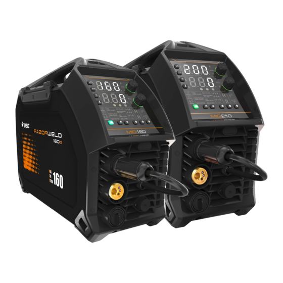
- Page 1 RAZORWELD di rw21odi RW16O MIG/TIG/STICK MULTI-SYSTEM 160AMP MTS MULTI-SYSTEM 210AMP MTS MULTI-SYSTEM INSTRUCTION MANUAL . RW160di/210di...
- Page 3 Thank you for selecting this new JASIC welding equipment! This operating manual contains important information on the use and maintenance of this product, as well as safe handling of the product. Please refer to technical parameters of the equipment in Technical Parameter section in this manual, and read the manual carefully before using the equipment for the first time.
- Page 4 Contents 1. Safety precautions ......................1.1. General safety ........................ 1.2. Other precautions ......................2. Description of symbols ..................... 3. Product overview ......................4. Technical parameters ....................... 5 . I nstallation ........................5.1. External interface description ..................5.2. Power installation......................5.3. MIG welding torch and earth cable connection ............. 5.4.
- Page 5 • Product will only be replaced if repair is not possible • Please view full Warranty term and conditions supplied with machine or at www.razorweld.com or at the back of this manual.
- Page 6 For your safety, please read this manual carefully before installing and operating this 1. Safety precautions JASIC equipment. Pay extra attention to all content marked with " ". All operations must be carried out by professional, suitably qualified persons! 1.1. General safety SAFETY INSTRUCTION These general safety norms cover both arc welding machines and plasma cutting machines unless otherwise noted.
- Page 7 Arc rays——May injure the eyes and burn the skin. The arc rays from all processes produce intense, visible and invisible (ultraviolet and infrared) rays that can burn eyes and skin. ·Wear an approved welding helmet fitted with an appropriate shade of filter lens to protect your face and eyes when working or watching.
- Page 8 Risks due to magnetic fields The magnetic fields created by high currents may affect the operation of pacemakers or electronically controlled medical equipment. Wearers of vital electronic equipment should consult their physician before beginning any arc welding, cutting, gouging or spot welding operations. Do not go near welding equipment with any sensitive electronic equipment as the magnetic fields may cause damage.
- Page 9 1.2. Other precautions Warning! Location The machine should be located in a suitable position and environment. Care should be taken to avoid moisture, dust, steam, oil or corrosive gases. Place on a secure level surface and ensure that there is adequate clearance around the machine to ensure natural airflow.
- Page 10 2. Description of symbols Warning! Read the Manual Electric shock risk warning WEEE tag Current unit "A" Wire feed speed unit "Inches/min" Inches/MIN MATERIAL Thickness of welding base metal "inch" THICKNESS Voltage unit "V" INDUCTANCE/ARC Inductance of MIG/arc force of MMA/STICK FORCE BURN MIG burn back time unit "ms"...
- Page 11 Welding Type Selector: Welding Base metal and Gas 0.030 0.035 Welding wire diameter 0.045 MIG/Lift TIG 2T operation MIG/Lift TIG 4T operation Standard MIG push torch SPOOL MIG spool torch Other function switching Remote controller MIG synergic function Inching wire feeding function Gas check function Page 10...
- Page 12 3. Product overview MIG160/MIG210 series This series are digital multi-process inverter DC MIG welders featuring advanced technology with excellent performance. They can be used to weld carbon steel, low-alloy steel, aluminum magnesium alloy and stainless steel, etc. The MIG mode of the welder features preset wire feed speed and welding voltage.
- Page 13 accurate. Anti-stick function: Prevents the welding electrode from sticking to the work piece during welding. STICK hot start function: Makes STICK arc ignition easier and more reliable. Lift TIG is controlled by the welding torch. On-demand fan: Prolongs the life span of fan and reduces accumulation of dust inside the machine.
- Page 14 4. Technical parameters Item Unit MIG160/MIG/MIG210 Parameters MIG160 Model MIG210 AC230V±15% Input voltage AC230V±15% 50/60 Input frequency 50/60 20@MIG 28.5@MIG Rated input current 14.4@TIG 19.1@TIG (AC230V) 18.5@MMA 25@MMA 29.2@MIG 34.3@MIG Rated input current 16.4@TIG 23.7@TIG (AC115V) 25.3@MMA 28.5@MMA 4.25@MIG 6.10@MIG Rated input power 3.24@TIG 4.66@TIG...
- Page 15 82.8@230V MIG 84.3@230V MIG Efficiency (%) 85.1@230V MMA 87.2@230V MMA (230V) 80.7@230V TIG 82.9@230V TIG 80.0@115V MIG 80.5@115V MIG Efficiency (%) 80.8@115V MMA 85.2@115V MMA (115V) 78.2@115V TIG 80.5@115V TIG 30@MIG 25@MIG 30@TIG Duty cycle (%) 25@TIG 30@MMA 25@MMA 0.99 Power factor 0.99 Insulation class...
- Page 16 5. Installation Warning! All connections shall be made with the power supply is turned off. Warning! Electric shock may cause death; after power failure, there is still a high voltage on the equipment, do not touch the live parts on the equipment. Warning! Incorrect input voltage may damage the equipment.
- Page 17 5.2. Power installation Warning! The electrical connection of equipment shall be carried out by suitably qualified personnel. Warning! All connections shall be made after the power supply is off. Warning! Incorrect voltage may damage the equipment. 1) Ensure the input voltage value is within the specified input voltage range. 2) Ensure that the power switch is turned off.
- Page 18 5.3. MIG welding torch and earth cable connection 5.3.1 Digital/analog MIG welding torch Junction box Grounding Power cord (Wiring diagram of MIG: DCEP) Pay attention to the polarity of wiring before MIG. Generally, there are two connection methods of DC welder: DCEN and DCEP. DCEN: The workpiece is connected to the positive polarity, and the polarity changeover connector is connected to the negative polarity;...
- Page 19 5.3.2 Spool Gun Junction box Grounding Power cord (Wiring diagram of spool torch: DCEP) Pay attention to the polarity of wiring before MIG. See section 5.3.1 for details. Take DCEP as an example: 1) Ensure that the power switch of the welder itself is turned off. 2) Insert the torch plug into the central socket on the front panel of the welder and tighten it clockwise.
- Page 20 5.4. STICK electrode holder and earth cable connection Junction box Grounding Power cord (Wiring diagram of STICK: DCEP) Pay attention to the polarity of the wiring before STICK. Generally, there are two connection methods of DC welding: DCEN and DCEP. DCEN: The electrode holder is connected to the negative polarity, and the workpiece is connected to the positive polarity;...
- Page 21 5.5. Lift TIG welding torch and earth cable connection Junction box Grounding Power cord (Wiring diagram of Lift TIG: DCEN) 1) Ensure that the power switch is turned off. 2) Insert the torch plug into the central socket on the front panel of the welder and tighten it clockwise.
- Page 22 5.6. Wired handheld remote controller / foot pedal controller connection (optional) (Wiring diagram of wired remote controller) Insert the 9-pin aviation plug of the handheld remote controller/foot pedal controller directly into the corresponding 9-pin aviation socket of the machine. Note! Please check with the seller whether the hardware and software versions of the machine support wired handheld remote controller before installation.
- Page 23 6. Control panel 6.1. Overview a.Parameter display A b.Parameter display B c.Welding mode selector d.Welding type selector e.Welding wire diameter selector f.MIG/Lift TIG operation mode selector g.Push/spool torch selector h.Enable remote control i.Synergic j.Inching feeding k.Gas check l.Parameter adjustment knob A m.Parameter adjustment knob B n.Alarm/protection indicator...
- Page 24 a. Parameter display A Parameter display A is used to display the current, wire feeding speed, and plate thickness parameters and error code. 1) When not welding, the preset value of current parameter will be displayed. If no operation is performed for a long time, the default parameters are displayed. 2) When welding, the actual output current value is displayed.
- Page 25 d. MIG type selection 1) In MIG mode, press the welding type selection keys to switch the welding type. 2) If the corresponding welding type indicator is on, it indicates that the welding type has been selected. e. Selection of MIG welding wire diameter selection 1) In MIG mode, press the corresponding function switching key to select an optional welding wire diameter for the welding type.
- Page 26 In MIG mode, press the corresponding function switching key to select the push torch or spool torch. 1) If the indicator is on, it indicates that the MIG is in push torch state. 2) If the indicator is on, it indicates that the MIG is in spool torch state. h.
- Page 27 Note: The icon of the pairing key may be different from the actual one due to different remote controller types. See the description of remote controller for specific operation. i. MIG synergic function switching 1) In MIG mode, press the "Synergic" function key to enable or disable the function.
- Page 28 2) In MMA or Lift TIG mode, the current parameter can be configured. 3) Rotate the adjustment knob to adjust the parameters. 4) Rotating the adjusting knob clockwise increases the parameter value, and rotating it counterclockwise decreases the value. 5) When the adjustment knob is rotated, the adjusted parameter is displayed in the parameter display area.
- Page 29 6.2. Barcode display* 1) Before welding, press and hold the "Welding Mode Selection" key and "Parameter Adjustment Knob A" for 3s at the same time, and the machine barcode will be displayed. 2) Press any key or wait for 20s to exit the barcode display. 3) The barcode is displayed in nine groups of data in the "Parameter Display A"...
- Page 30 Restored Restored Parameter Parameter Parameter Option Remarks Name Value Value MIG160 series MIG210 series Burn back time 0.2S 0.2S Burn back voltage Inductance Pre-flow time 0.1S 0.1S Post-flow time 0.5S 0.5S parameters Welding voltage 19.0V 19.0V Wire feeding speed Inches/min Inches/min Crater voltage 19.0V...
- Page 31 6.4. Welding engineer mode functions The Welding Engineer Mode function allows users to set/modify the default parameters/functions as follows: 1) Press and hold "Parameter Adjustment Knob A" for 5s in startup state. 2) After pressing and holding the "Parameter Adjustment Knob" for 2s, the machine will count down from 3s;...
- Page 32 Set the MIG/TIG welding parameters according to the "Welding Mode" when in Welding Engineer Mode . 1) If the "Welding Mode" is MIG, set the MIG MIG: 0.5 post-flow time, with range 0-5.0, accuracy of 0.5, and Post-flow time F04 Lift TIG: 5 unit of seconds.
- Page 33 7. Welding function operation Warning! Before turning on the power supply make sure that the equipment is disconnected to the output. Otherwise, an unexpected arc may be started when the power is turned on. This can cause damage to the work piece and to personnel.
- Page 34 7.1.2 Select MIG mode (MIG mode: Synergic enabled) 1) Press the "Welding Mode Selection" key to select MIG mode. 2) Use the corresponding function switching key to select the welding type, wire diameter, operation method and welding torch type. 3) Enable/disable the "Synergic" function. 4) Use "Parameter Adjustment Knob A/B"...
- Page 35 (Input 115V Parameter options or range Parameter Name MIG160 MIG210 Wire feed speed 79~512 79~433 (Inch/min) Welding voltage 11~24 11~22 Inductance -10~10 -10~10 Burn back time 0~800 0~800 (ms) 7.1.4 Set welding parameters with Synergic enabled (Setting welding current) (Setting wire feed speed) (Setting plate thickness) 1) Press "Parameter Adjustment Knob A"...
- Page 36 7.1.5 Use of digital torch or spool torch (optional) In addition to the common push torch, these inverter welders also support digital MIG torch and spool torch. The parameters are adjusted through the keys on the digital torch or the adjustment knob on the spool torch.
- Page 37 (Select spool torch) 1) After connecting the spool torch with the welder, select the "Spool Torch" mode of the welding torch type. 2) When the remote control function is enabled, the "Wire Feed Speed" is adjusted by the potentiometer of spool torch. 3) When the remote control function is disabled, the "Wire Feed Speed"...
- Page 38 Welding sequence of MIG 2T/4T operation Mode Schematic diagram Pre-flow Torch trigger No-load voltage Gas supply Anti-stick time Post-flow supply time Output voltage Wire feed Slow wire feed Welding current Welding Torch trigger Pre-flow No-load voltage Gas supply Anti-stick time Post-flow supply time Output voltage Wire feed...
- Page 39 7.1.7 Turn off the power supply after welding The power switch is located on the rear panel of the machine and set it to the "OFF" position. After a time delay, the panel indicator is off and the welder stops working. 7.2.
- Page 40 2.0/5/64" 40~65 2.0~3.2 2.5/3/32" 50~80 5/64"- 1/8"" 3.2/1/18" 100~130 3.2/1/18" 100~130 3.2~4.0 1/8" - 5/32" 4.0/5/32" 160~210 5.0/13/64" 200~270 ≥5/13/64"" 6.0/15/64" 220~300 NOTE! The operator should set the functions that meet the welding requirements. If the selections are incorrect, this may lead to problems such as an unstable arc, spatter, or sticking of the electrode to the work piece.
- Page 41 7.2.5 Turn off the power supply after welding (Same as section 7.1.7) The power switch is located on the rear panel of the machine and set it to the "OFF" position. After a time delay, the panel indicator is off and the welder stops working. 7.3.
- Page 42 7.3.4 Start welding Description of MIG 2T/4T operation 2T operation mode 4T operation mode Step 1: Press the torch trigger to start Step 1: Press the torch trigger for the first time to welding. start welding. Step 2: Release the trigger to stop Step 2: Release the trigger for the first time to welding.
- Page 43 7.4. Standby (Standby state interface) 1) Enter standby state: In both MIG and Lift TIG modes, the machine will enter standby state and close the display window in the operation panel if there are no welding or panel operations for a long time. The default standby response time is 10 minutes. 2) Exit standby state: In standby state, any operation on the welder will cause it to exit standby state, including welding, key/knob operation, pressing the torch trigger, or operating the paired and valid remote controller, etc.
- Page 44 8. Maintenance Warning! The following operation requires sufficient professional knowledge on electric aspects and comprehensive safety knowledge. Make sure the input cable of the machine is disconnected from the electricity supply and wait for 5 minutes before removing the machine covers. Please note: The following should only be carried out by an authorised electrical technician.
- Page 45 9. Troubleshooting Warning! Before machines are dispatched from the factory, they have already been checked thoroughly. The machine should not be tampered with or altered. Maintenance must be carried out carefully. If any wire becomes loose or is misplaced, it maybe potentially dangerous to user! Only professional maintenance personnel should repair the machine! Ensure the power is disconnected before working on the machine.
- Page 46 · The torque knob of the wire feeder is not · Properly adjust the torque knob of adjusted properly the wire feeder · The wire feed roller and The welding welding wire are · Match the wire feed roller with the current is configured differently welding wire...
- Page 47 Elimination of general problems in Lift TIG Symptom Reasons Troubleshooting When the temperature is too low, leave The ambient the machine work for a while. The After startup, the fan temperature is too low temperature in standby will rise the fan does not turn or the and resume normal operation.
- Page 48 The voltage of the power grid fluctuates · Check whether the power grid is normal Unstable seriously or the joint and connect the power connector. current in contact with the power · Use different power cords to connect welding grid is poor. equipment that could seriously interfere process Serious interference...
- Page 49 9.2. Alarm and solutions Error Possible Category Countermeasure cause code Continuously Restart the welder. If it is still in overcurrent output the protection, contact the after-sales department of Overcurrent maximum the company. capacity protection current of welder Turn it off and on again. If this the alarm cannot be eliminated and the grid voltage remains too low, Input network Undervoltag...
- Page 50 9.3. Common MIG malfunction When the welding conditions do not meet the requirements, the phenomena described in the following table will occur: Table 9.3 Common MIG malfunction Unsuitable Unsuitable Welding Result Result Welding Condition Condition The arc is unstable, The arc is too long and the resulting in welding fusion spatter increases.
- Page 51 10. Packaging, transportation, storage and waste disposal 10.1. Transportation requirements In the process of handling the equipment, it should be handled with care, and should not be dropped or severely impacted. Avoid moisture and rain during transportation. 10.2. Storage conditions Storage temperature:-25 ℃...
- Page 52 11. After-sales service 11.1. Warranty card Each welder includes a warranty card. Please fill in the relevant information. Read and keep the warranty card carefully. 11.2. Maintenance Perform preliminary troubleshooting or record faults according to the common malfunction analysis and solution checklist. To repair or replace the device, contact a local dealer. Please use accessories or consumables provided by JASIC Technologies America Inc.
- Page 53 Appendixes Appendix 1: Wiring diagram Wiring diagram - MIG160/MIG210 Note! Some models do not support PCB2 and 9-pin aviation socket. Please confirm with the seller whether the machine supports this function before purchasing. Page 52...
- Page 54 Appendix 2: List of common spare parts List of common spare parts - MIG160/MIG210 Page 53...
- Page 55 List of spare parts Material Material Name Quantity SN Name Quantity code code 51002374 Quick socket 51000691 Hall sensor Quick 51000684 51000824 Wire feeder coupling Display 51004661 51000944 Central socket panel 9-pin aviation socket 51001899 Knob 51000686 and cable Wire feeder 51001033 51001816 Fan@MIG160...
- Page 56 Spare Parts for Tweco 2 style torches and Spool gun Torch Model Description Part Number EAN CODE 15 FT Welding Torch Classic Style TWC2-15FTE 0680474943777 10 FT Welding Torch Euro Style Handle TWC2-10FTE 0680474944095 TWC2 Contact Tips Part Number Description EAN CODE PRW14-30 Contact tip 0.8mm / 0.030”...
- Page 57 SPOOL GUN EXPLODED DIAGRAM SPGLBT200 Page 56...
- Page 58 RAZORWELD RAZOR 160/210PFC OPERATING MANUAL NOTES: _____________________________________________________________________________________________________________________ _____________________________________________________________________________________________________________________ _____________________________________________________________________________________________________________________ _____________________________________________________________________________________________________________________ _____________________________________________________________________________________________________________________ _____________________________________________________________________________________________________________________ _____________________________________________________________________________________________________________________ _____________________________________________________________________________________________________________________ _____________________________________________________________________________________________________________________ _____________________________________________________________________________________________________________________ _____________________________________________________________________________________________________________________ _____________________________________________________________________________________________________________________ _____________________________________________________________________________________________________________________ _____________________________________________________________________________________________________________________ _____________________________________________________________________________________________________________________ _____________________________________________________________________________________________________________________...
- Page 59 JASIC TECHNOLOGIES AMERICA INC 25503 74th AVE A, KENT, WA 98032 U.S.A WWW.RAZORWELD.COM SALES@RAZORWELD.COM...
Need help?
Do you have a question about the RW160di and is the answer not in the manual?
Questions and answers