Table of Contents
Advertisement
TopPage
[1]
SPECIFICATION ...........................................1-1
[2]
EXTERNAL DIMENTIONS ............................1-3
[3]
WIRING DIAGRAMS .....................................1-5
[4]
ELECTRICAL PARTS....................................1-5
[1]
BLOCK DIAGRAMS ......................................2-1
[2]
[3]
FUNCTION ....................................................2-8
CHAPTER 3. FUNCTION AND OPERATION OF PRO-
TECTIVE PROCEDURES
[1]
TROUBLESHOOTING GUIDE ......................3-1
[2]
CHART ..........................................................3-2
Parts marked with "
" are important for maintaining the safety of the set. Be sure to replace these parts with specified ones for maintaining the
safety and performance of the set.
SERVICE MANUAL
SPLIT TYPE
ROOM AIR CONDITIONER
MODELS
CONTENTS
[1]
REFRIGERATION CYCLE..................... . ....... 4-1
[2]
PERFORMANCE CURVES ................... . ....... 4-2
[3]
WORKS ................................................. . ....... 4-3
[1]
INDOOR UNIT ....................................... . ....... 5-1
[2]
OUTDOOR UNIT ................................... . ....... 5-5
........2-3
Parts Guide
S3011AYXPC8LRT
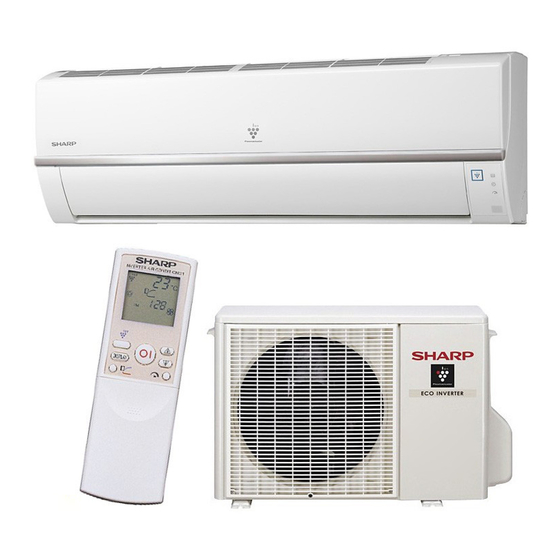
INDOOR UNIT
AY-XPC18LR
AY-XP24LR
OUTDOOR UNIT
AE-X18LR
AE-X24LR
This document has been published to be used for
after sales service only.
The contents are subject to change without notice.
AYXPC18LR
Advertisement
Table of Contents

Subscribe to Our Youtube Channel
Related Manuals for Sharp AY-XPC18LR


Summary of Contents for Sharp AY-XPC18LR
-
Page 1: Table Of Contents
TopPage AYXPC18LR SERVICE MANUAL S3011AYXPC8LRT SPLIT TYPE ROOM AIR CONDITIONER INDOOR UNIT MODELS AY-XPC18LR AY-XP24LR OUTDOOR UNIT AE-X18LR AE-X24LR CONTENTS CHAPTER 1. PRODUCT SPECIFICATIONS CHAPTER 4. REFRIGERATION CYCLE SPECIFICATION ...........1-1 REFRIGERATION CYCLE......4-1 EXTERNAL DIMENTIONS ......1-3 PERFORMANCE CURVES ......4-2 WIRING DIAGRAMS ........1-5... -
Page 2: Chapter 1. Product Specifications
AYXPC18LR CHAPTER 1. AYXPC18LR PRODUCT SPECIFICATIONS Service Manual [1] SPECIFICATION 1. AY-XPC18LR – AE-X18LR MODEL INDOOR UNIT OUTDOOR UNIT ITEMS AY-XPC18LR AE-X18LR Cooling capacity (Min– Max.) 5.00 (1.40 - 5.70) Heating capacity (Min–Max.) 5.70 (1.10 - 8.00) Moisture removal (at cooling)✩... - Page 3 AYXPC18LR 2. AY-XP24LR / AE-X24LR MODEL INDOOR UNIT OUTDOOR UNIT ITEMS AY-XP24LR AE-X24LR Rated cooling capacity (Min– Max.) 7.00 (1.50- 8.00) Rated heating capacity (Min–Max.) 7.50 (1.10 - 9.50) Moisture removal (at cooling)✩ Liters/h Electrical data Phase Single Rated frequency Rated voltage 220-240 Rated current ✩...
-
Page 4: External Dimentions
AYXPC18LR [2] EXTERNAL DIMENTIONS 1. Indoor unit 1040 Remote controller 1 – 3... - Page 5 AYXPC18LR 2. Outdoor unit 3. Installation dimension 1040(Unit size) Center of wall hole: Leftward piping Outline of indoor unit Center of wall hole: Backward piping 1 – 4...
-
Page 6: Wiring Diagrams
AYXPC18LR [3] WIRING DIAGRAMS 1. Indoor unit MAIN CONTROL BOARD UNIT SUB CONTROL BOARD UNIT CN10 THERMAL FUSE POWER BROWN ORANGE SUPPLY OKR^ CIRCUIT YELLOW BLUE SERIAL BLACK SIGNAL (VALVE TEMP.) CONTROL CIRCUIT (HORIZONTAL) (VERTICAL) GREEN- YELLOW 2. Outdoor unit [4] ELECTRICAL PARTS 1. -
Page 7: Chapter 2. Explanation Of Circuit And Op- Eration Block Diagrams
AYXPC18LR CHAPTER 2. AYXPC18LR EXPLANATION OF CIRCUIT AND OPERATION Service Manual [1] BLOCK DIAGRAMS 1. Indoor unit DC power supply circuit 2.5A Fan motor phase control circuit Indoor fan motor FUSE1 Rotation pulse input circuit Fan motor pulse detect AC clock circuit Louvre motor drive circuit Flow direction control Remote controller signal reception circuit... - Page 8 AYXPC18LR 2. Outdoor unit AC clock circuit protection protection Power supply Smoothing Filter Power Supply (AC power ) PFC Module circuit circuit circuit CPU oscillator circuit protection 3.15A DC overvoltage detection circuit protection Outdoor fan Outdoor fan drive circuit 4-way valve relay drive circuit 4-way valve DC overcurrent detection circuit protection...
-
Page 9: Microcomputer Control System
AYXPC18LR [2] MICROCOMPUTER CONTROL SYSTEM 1. Indoor unit 2 – 3... - Page 10 AYXPC18LR FROM LOUVER MOTOR (VERICAL) FROM CLUSTER GENERATOR FROM LOUVER MOTOR (HORIZONTAL) TO TERMINAL BOARD FROM THERMISTOR FROM FAN MOTOR TOP "N" FROM TERMINAL BOARD TOP "I" FROM TERMINAL BOARD TOP TO TERMINAL BOARD TOP "2" TO EVAPORATOR AND TERMINAL BOARD "E" Printed wiring board 2 –...
- Page 11 AYXPC18LR 2. Outdoor unit Electronic control circuit diagram 2 – 5...
- Page 12 AYXPC18LR from CONTROL BOARD P.W.B. BCN13 from ELECTROLYTIC CAPACITOR C9 (-) from CONTROL BOARD P.W.B. MRY1OUT from CONTROL BOARD P.W.B. "T6" from ELECTROLYTIC from PFC COIL from PFC COIL CAPACITOR C9 (+) PFCM P.W.B. from ELECTROLYTIC CAPACITOR C10(+) from CONTROL PWB CN14 from ELECTROLYTIC CAPACITOR C10(-) from COMPRESSOR TERMINAL...
- Page 13 AYXPC18LR from TERMINAL BOARD "L" (POWER SUPPLY) to TERMINAL BOARD "N" from TERMINAL BOARD to TERMINAL BOARD "1" (THERMAL FUSE) from 4WAY VALVE from PFCM P.W.B. "AC1" from DC FAN MOTOR CONTROL BOARD P.W.B. 2 – 7...
-
Page 14: Function
AYXPC18LR [3] FUNCTION 1. Restart control 5. Indoor unit overheat prevention control Once the compressor stops operating, it will not restart for 180 sec- During heating operation, if the temperature of the indoor unit heat onds to protect the compressor. exchanger exceeds the indoor unit heat exchanger overheat preven- tion temperature (about 45 to 54°C) which is determined by the operat- Therefore, if the operating compressor is shut down from the remote... - Page 15 When a circuit breaker is used to control the ON/OFF operation, Peak control current please insert a jumper as described above. Cooling operation Heating operation AY-XPC18LR Approx. 9.5 A Approx. 13.0 A 15. Self-diagnostic malfunction code display AY-XP24LR Approx. 15.0 A Approx.
-
Page 16: Full Power Operation
AYXPC18LR 17. Airflow control 20. Dehumidifying operation control If the room temperature is 26°C or higher when dehumidifying opera- 17.1. VERTICAL AIR FLOW DIRCTION tion starts, the dehumidifying operation provides a low cooling effect in 1) Press the SWING button ( ) on the remote control once. -
Page 17: Energy Saving Operation
Since this air conditioner model is inverter type, com- temperature) pressor output will also vary in the same manner. As a result this will (AY-XPC18LR: SINGLE USE OR AY-XP24LR) help saving electricity cost. COMPRESSOR INTER- 28.2. Heat Operation... - Page 18 AYXPC18LR 29. PFC MODULE CIRCUIT These model’s circuit uses PFCM (Power Factor Correction Module) and IPM as the figure below for the high efficiency operation of compressor. Active filter Choke coil Rectifica- tion circuit Comp Noise filter ressor 200V circuit Positional detection Voltage raise...
- Page 19 AYXPC18LR Control IGBT 29.3. PFC Module Driving Electronics Circuit The PFC Module circuit operates continuously while the compressor is driving. The microcomputer detects output DC voltage of the PFC Module circuit with pin 69, and controls to keep the DC voltage to be the target value. The microcomputer controls so that the input AC current wave form will become a sine wave detecting the input AC voltage of the PFC Module circuit with pin 71 and detecting AC current wave form with pin 72.
-
Page 20: Troubleshooting Guide
AYXPC18LR CHAPTER 3. AYXPC18LR FUNCTION AND OPERATION OF PROTECTIVE PROCEDURES Service Manual [1] TROUBLESHOOTING GUIDE 1. SELF-DIAGNOSIS FUNCTION AND DISPLAY MODE 1) To call out the content of the self-diagnosis memory, hold down the emergency operation button for more than five seconds when the indoor unit is not operating. -
Page 21: Chart
AYXPC18LR [2] CHART 3 – 2... - Page 22 AYXPC18LR 3 – 3...
- Page 23 AYXPC18LR 3 – 4...
- Page 24 AYXPC18LR 3 – 5...
- Page 25 AYXPC18LR Figure 1 Temperature properties of indoor thermistors Room temperature Thermistor Signal Color thermistor TH1 ( 3 - 4 ) Room temperature Yellow Pipe temperature Pipe temperature Orange thermistor TH2 ( 1 - 2 ) Valve temperature Black Valve temperature To measure the resistance, first remove thermistor TH3 ( 5 - 6 ) the soldering as shown at right.
-
Page 26: Chapter 4. Refrigeration Cycle
AYXPC18LR CHAPTER 4. AYXPC18LR REFRIGERATION CYCLE Service Manual [1] REFRIGERATION CYCLE 1. FLOW OF REFRIGERANT AY-XP24LR AY-XPC18LR Indoor unit Indoor unit Evaporator Evaporator Flare coupling Flare coupling Flare coupling Flare coupling Outdoor unit Outdoor unit 3-way 3-way valve valve 3-way... -
Page 27: Performance Curves
[2] PERFORMANCE CURVES NOTE: 1) Indoor fan speed: Hi 2) Vertical adjustment louver “45°“, Horizontal adjustment louver “front” 3) Indoor air temp.: Cooling 27°C, Heating 20°C 4) Power source: 230V, 50Hz 1. AY-XPC18LR 1.1. Cooling 1.2. Heating 1700 1600 1600... -
Page 28: Refrigerant Pipe Installation Works
[3] REFRIGERANT PIPE INSTALLATION WORKS Refrigerant pipe length and level difference between the indoor and outdoor units. MODEL PIPE SIZE STANDARD PERMISSIBLE PERMISSIBLE LEVEL CHARGE LESS ADDITIONAL LENGTH DIFERENCE LENGTH CHARGE LIQUID AY-XPC18LR 1/2" 1/4" AY-XP24LR 5/8" 1/4" 4 – 3... -
Page 29: Chapter 5. Disassembling Procedure
AYXPC18LR CHAPTER 5. AYXPC18LR DISASSEMBLING PROCEDURE Service Manual If, in carrying out repairs and modifications, the work requires the use of arc- and flame-producing apparatus, such as welding, brazing and soldering equipment, this work shall only be started after the rooms have been thoroughly ventilated. While the work is being carried out, the mechanical venti- lation, if any, shall be kept in constant operation and all windows and doors kept open. - Page 30 AYXPC18LR 24000BTU MODEL 7) Remove a screw fixing the control cover. 9) Remove 2 screws fixing the cover. Unfix 2 hooks and remove the control cover. Unfix 2 hooks and remove the PWB holder. Screw Cover 10)Remove a screw fixing the thermistor holder. Remove the thermistor holder.
- Page 31 AYXPC18LR 13)Remove 4 screws fixing the drain pan and pull drain pan toward 16)Remove the 2 screws fixing the side coder L. you. Left side 17)Remove 3 screws fixing the side cover R and remove the and remove the evaporator from the cabinet. Right side 14)Remove the drain cover from the evaporator.
- Page 32 AYXPC18LR 2. ELECTRIC CONTROL BOX 2) Open the horizontal louver to remove it from the holders. 1) Remove a screw fixing the terminal board. 3) Remove the holders. 2) Pull the control board unit. Holder 4) Tilt the hooks of vertical louvers inside, and pull them up. 3.
-
Page 33: Outdoor Unit
AYXPC18LR [2] OUTDOOR UNIT 1. Remove the 4 screws fixing the side cover and valve cover then 4. Remove the 5 screws fixing the motor angle T, then remove it. remove them.. Motor angle T Side cover 5. Remove the 2 screws fixing the angle, then remove it. Valve cover Angle 2. - Page 34 AYXPC18LR 7. Cut the insulators. 8. Remove the 2 screws fixing the control box cover, then remove it. CAUTION: Discharge electrytic capacitor before touching this capaci- tor or other components or wirings. Control box cover Control box assembly 9. Disconnect the 4 connectors and the 3 terminals. Thermistor Coil of reverse valve Coil of expansion...
- Page 35 AYXPC18LR 1) Tilt the side cabinet R, then remove the left side hook. 13.Remove the 2 screws fixing the bulkhead, then remove it. Side cabinet R 2) Keep the above condition and remove the side cabinet R by sliding to sideways. Side cabinet R 14.Remove the compressor covers(3pcs).
- Page 36 AYXPC18LR 15.Cut the fixing bands and remove thermistors. 18.Disconnect 3 terminals. NOTE: Caution to the position of connectors when reinstalling. Orange (C) White (S) Thermistor Red (R) Thermistor 19. Remove the 1 nut fixing the propeller fan, then remove it. 16.Remove the compressor cover.
- Page 37 AYXPC18LR 21.Remove the 4 screws fixing the fan motor, then remove it. Green lead wire Cut the fixing band. Orange lead wire 23.How to disassemble the control box assembly. 1) Remove the 4 screws fixing the PWB, then remove it. 22.Position of the thermistors.
- Page 38 AYXPC18LR 5 – 10...
-
Page 39: Parts List
AYXPC18LR PartsGuide PARTS LIST SPLIT TYPE AIR CONDITIONER INDOOR UNIT OUTDOOR UNIT MODELS AY-XPC18LR AE-X18LR AY-XP24LR AE-X24LR CONTENTS INDOOR UNIT PARTS CYCLE PARTS ACCESSORY PARTS CONTROL BOX PARTS INDOOR PACKING PARTS OTHER OUTDOOR PARTS OTHER PARTS OUTDOOR PACKING PARTS OUTDOOR UNIT PARTS ... - Page 40 AYXPC18LR [1] INDOOR UNIT PARTS 1-58 1-28 1-36 2-19 1-60 2-19 1-59 2-24 1-35 1-26 1-34 1-18 1-43 1-29 2-23 1-41 2-13 1-10 2-24 1-14 2-17 2-16 1-17 1-13 1-12 2-20 2-21 1-13 2-25 2-10 1-25 1-16 2-22 1-22 1-11 1-37 1-54 1-53...
- Page 41 AYXPC18LR PRICE PART PARTS CODE DESCRIPTION RANK MARK RANK [1] INDOOR UNIT PARTS Fan Motor Sub Assembly CMOT-A524JBKZ Motor Cover PCOV-B593JBFZ Bearing Assembly CHLD-A067JBK0 Cabinet Sub Assembly DCHS-A761JBKZ Cross Flow Fan NFANCA091JBEZ Drain Pan Sub Assembly DSRA-A339JBKZ Louver Link L MJNTPA158JBFA Louver Link R MJNTPA159JBFA...
- Page 42 AYXPC18LR [2] ACCESSORY PARTS 4-11 4-12 PRICE PART PARTS CODE DESCRIPTION RANK MARK RANK [2] ACCESSORY PARTS Remote Control CRMC-A797JBEZ Battery Pack UBATUA027JBE0 Special screw LX-BZA357JBEZ Special Nut LX-NZA207JBEZ Drain Joint (for 1800 Btu type, accessory kit parts of OUTDOOR UNIT) LPFT-A134JBFZ Drain Tray (for 1800 Btu type, accessory kit parts of OUTDOOR UNIT) LPFT-A135JBFZ...
- Page 43 AYXPC18LR [5] OUTDOOR UNIT PARTS PRICE PART PARTS CODE DESCRIPTION RANK MARK RANK [5] OUTDOOR UNIT PARTS Fan Motor CMOTLB426JBEZ Fan Motor Angle Sub LANGKA253JBPZ...
- Page 44 AYXPC18LR PRICE PART PARTS CODE DESCRIPTION RANK MARK RANK [5] OUTDOOR UNIT PARTS Motor Angle LANGKA267JBPZ Motor Angle T LANGKA268JBPZ 1-4-1 Angle Top Seal PSEL-E186JBEZ Front Panel L GCAB-A409JBTA 1-5-1 Front Panel L Seal PSEL-E132JBEZ GGADFA042JBFA Fan Guard Front Panel R GCAB-A408JBTA Handle JHNDPA016JBFA...
- Page 45 AYXPC18LR [6] CYCLE PARTS 1-39 1-38 1-15 1-22 (FOR AEX24LR) 6-22 1-23 (FOR AEX18LR) 2-5-1 (FOR AEX18LR) 2-5-2 1-24 6-22 1-23 6-21 (FOR AEX24LR) 2-13 2-15 2-16 2-17 2-14 2-12 2-3-3 2-18 2-19 2-21 2-20...
- Page 46 AYXPC18LR PRICE PART PARTS CODE DESCRIPTION RANK MARK RANK [6] CYCLE PARTS 1-23 Thermistor Spring MSPR-A026JBE0 1-24 Thermistor Spring MSPR-A036JBE0 1-15 Side Cabinet R Seal PSEL-E120JBEZ 1-22 Thermistor Holder LHLD-B097JBFA 1-38 Condenser Seal A PSEL-E184JBEZ 1-39 Condenser Seal B PSEL-E185JBEZ Base Pan Sub Assembly CCHS-B151JB1Z Base Stand...
- Page 47 AYXPC18LR [7] CONTROL BOX PARTS 3-59 3-58 3-53 3-39 (to CN8A) 3-54 3-13 3-19 3-37 3-36 3-21 3-20 3-13 3-45 3-36 3-44 3-24 3-25 3-26 3-16 3-42 3-17 3-61 3-41 3-40 3-51 3-50 3-38 PRICE PART PARTS CODE DESCRIPTION RANK MARK RANK [7] CONTROL BOX PARTS...
- Page 48 AYXPC18LR PRICE PART PARTS CODE DESCRIPTION RANK MARK RANK [7] CONTROL BOX PARTS 3-21 PFC Control Board Uni DSGY-E030JBKZ 3-24 Haet Sink PRDAFA239JBEZ 3-25 PWB Spacer PSPA-A150JBZZ 3-26 Comp. Cord (QM101(U,V,W) - COMP) QW-IZA141JBZZ 3-36 Ferrite Core RFIL-A064JBE0 3-37 RTRN-A300JBZZ Active Coil 3-38 Capacitor Clamp...
- Page 49 AYXPC18LR [9] OUTDOOR PACKING PARTS i d e PRICE PART PARTS CODE DESCRIPTION RANK MARK RANK [9] OUTDOOR PACKING PARTS Bottom Pad Assembly CPADBA164JBKZ Packing Pad Assembly CPADBA165JBKZ Packing Case [18] SPAKCC840JBEZ Packing Case [24] SPAKCC861JBEZ...
- Page 50 AYXPC18LR INDEX PRICE PART PRICE PART PARTS CODE PARTS CODE RANK MARK RANK RANK MARK RANK LHLDWA039JBEZ 7-3-40 [ C ] LHLDWA040JBEZ 7-3-41 CCHS-B151JB1Z 6-2-1 LPFT-A134JBFZ 2-4-6 CCOV-A283JBKZ 1-2-3 LPFT-A135JBFZ 2-4-7 CCOV-A327JBKZ 1-1-21 LPLT-A058JBPZ 1-1-17 CCYC-C523JBKZ 1-3-9 LX-BZA075JBE0 1-5-1 CCYC-C533JBKZ 1-3-9 "...
- Page 51 AYXPC18LR PRICE PART PRICE PART PARTS CODE PARTS CODE RANK MARK RANK RANK MARK RANK PSEL-E186JBEZ 5-1-4-1 XJTS740P10000 8-6-11 PSEL-E199JBEZ 1-1-56 XTPS730P12XS0 8-6-12 PSEN-A044JBKZ 1-3-2 XTPS740P25000 1-5-2 PSEN-A053JBKZ 1-3-3 XTTS745P30000 2-4-8 PSHE-A278JBEZ 1-1-21-4 PSHE-A313JBEZ 7-3-42 PSKR-A372JBPZ 5-1-16-1 PSPA-A082JBE0 7-3-44 PSPA-A150JBZZ 7-3-25 PSPA-A173JBEZ 7-3-45...
- Page 52 EndPage – 1...
Need help?
Do you have a question about the AY-XPC18LR and is the answer not in the manual?
Questions and answers