Table of Contents
Advertisement
Quick Links
Download this manual
See also:
Owner's Manual
Model(s):
NEVO4236I
NEVO3630I
• Important operating and
maintenance instructions
included.
WARNING:
FIRE OR EXPLOSION HAZARD
Failure to follow safety warnings exactly
could result in serious injury, death, or
property damage.
• DO NOT store or use gasoline or other fl am-
mable vapors and liquids in the vicinity of this
or any other appliance.
• What to do if you smell gas
- DO NOT try to light any appliance.
- DO NOT touch any electrical switch. DO
NOT use any phone in your building.
- Leave the building immediately.
- Immediately call your gas supplier from
a neighbor's phone. Follow the gas sup-
plier's instructions.
- If you cannot reach your gas supplier, call
the fi re department.
• Installation and service must be performed
by a qualifi ed installer, service agency, or the
gas supplier.
In the Commonwealth of Massachusetts installation
must be performed by a licensed plumber or gas fi tter;
See Table of Contents for location of additional
Commonwealth of Massachusetts requirements.
CAUTION
DO NOT DISCARD THIS MANUAL
Read, understand and follow
•
these instructions for safe
installation and operation.
Heatilator • Evolution •
4065-114 Rev. X • 9/15
Owner's Manual
Installation and Operation
Leave this manual with
•
party responsible for
use and operation.
DANGER
DO NOT TOUCH GLASS
NEVER ALLOW CHILDREN
A barrier designed to reduce the risk of
burns from the hot viewing glass is provided
with this appliance and shall be installed for
the protection of children and other at-risk
individuals.
This appliance may be installed as an OEM
installation in manufactured home (USA
only) or mobile home and must be installed
in accordance with the manufacturer's
instructions and the Manufactured Home
Construction and Safety Standard, Title 24
CFR, Part 3280 in the United States, or the
Standard for Installation in Mobile Homes,
CAN/CSA Z240 MH Series, in Canada.
This appliance is only for use with the type(s)
of gas indicated on the rating plate. This
appliance is not convertible for use with other
gases, unless a certifi ed kit is used.
HOT GLASS WILL
CAUSE BURNS.
UNTIL COOLED.
TO TOUCH GLASS.
1
Advertisement
Table of Contents

Related Manuals for Heatilator NEVO4236I


Summary of Contents for Heatilator NEVO4236I
- Page 1 fi tter; appliance is not convertible for use with other See Table of Contents for location of additional gases, unless a certifi ed kit is used. Commonwealth of Massachusetts requirements. Heatilator • Evolution • 4065-114 Rev. X • 9/15...
-
Page 2: Congratulations
As the owner of a new fi replace, you’ll want to read and Your new Heatilator gas fi replace will give you years of carefully follow all of the instructions contained in this durable use and trouble-free enjoyment. Welcome to the owner’s manual. -
Page 3: Table Of Contents
A. Select Appliance Location B. Construct the Appliance Chase 14 Finishing C. Clearances A. Mantel and Wall Projections D. Mantel and Wall Projections B. Facing Material 6 Termination Locations A. Vent Termination Minimum Clearances Heatilator • Evolution • 4065-114 Rev. X • 9/15... - Page 4 A. Intellifi re™ Plus Intermittent Ignition System 17 Reference Materials A. Appliance/Decorative Front Dimension Diagrams 60 B. Vent Components Diagrams C. Service Parts D. Optional Components E. Contact Information = Contains updated information. Heatilator • Evolution • 4065-114 Rev. X • 9/15...
-
Page 5: Limited Lifetime Warranty
Limited 3 years Firebox and heat exchanger Lifetime All replacement parts 90 Days beyond warranty period See conditions, exclusions, and limitations on next page. 4021-645G 2/15 Page 1 of 2 Heatilator • Evolution • 4065-114 Rev. X • 9/15... - Page 6 THE EXTENT PROVIDED BY LAW, HHT MAKES NO EXPRESS WARRANTIES OTHER THAN THE WARRANTY SPECIFIED HEREIN. THE DURATION OF ANY IMPLIED WARRANTY IS LIMITED TO DURATION OF THE EXPRESSED WARRANTY SPECIFIED ABOVE. 4021-645G 2/15 Page 2 of 2 Heatilator • Evolution • 4065-114 Rev. X • 9/15...
-
Page 7: Listing And Code Approvals
Listing and Code Approvals A. Appliance Certifi cation C. BTU Specifi cations Novus NEVO3630I NEVO4236I MODELS: NEVO4236I, NEVO3630I Max/Min Input Rate (NG) 20,000/10,000 25,000/12,500 LABORATORY: Underwriters Laboratories, Inc. (UL) Orifi ce Size (NG) 0.083 0.089 / #43 TYPE: Vented Gas Fireplace Heaters... -
Page 8: Requirements For The Commonwealth Of Massachusetts
See Gas Connection section for additional Common- read, in print size no less than one-half (1/2) in. in size, wealth of Massachusetts requirements. “GAS VENT DIRECTLY BELOW. KEEP CLEAR OF ALL OBSTRUCTIONS”. Heatilator • Evolution • 4065-114 Rev. X • 9/15... -
Page 9: User Guide
• Keep remote controls out of reach of children. • Never leave children alone near a hot fi replace, whether operating or cooling down. Figure 2.1 General Operating Parts Heatilator • Evolution • 4065-114 Rev. X • 9/15... -
Page 10: Fan Kit (Optional)
Contact your dealer or Hearth & Home Technologies if the barrier is not present or help is needed to properly install one. For more information refer to the instructions supplied with your decorative door or front. Heatilator • Evolution • 4065-114 Rev. X • 9/15... -
Page 11: Ipi Battery Tray/Battery Installation
Batteries should only be installed for use during power WARNING! Risk of Fire or Asphyxiation! DO NOT oper- outages. See Section H. ate fi replace with fi xed glass assembly removed. Heatilator • Evolution • 4065-114 Rev. X • 9/15... -
Page 12: Lighting Instructions (Ipi)
Keep burner and control compartment clean. See installation and operating instruc- Propane Installation code, CSA B149.1. tions accompanying appliance. For additional information on operating your 593-913i Hearth & Home Technologies fi replace, please refer to www.fi replaces.com. Heatilator • Evolution • 4065-114 Rev. X • 9/15... -
Page 13: After Fireplace Is Lit
fl ame burn continually? turned off. Some optional control systems available with IPI models may allow pilot fl ame to remain lit. In a standing pilot system the pilot will always stay on. Heatilator • Evolution • 4065-114 Rev. X • 9/15... -
Page 14: Maintenance And Service
Carefully set fi xed glass assembly in place on fi replace. Hold glass in place with one hand and secure glass latches with the other hand. • Reinstall door or decorative front. Heatilator • Evolution • 4065-114 Rev. X • 9/15... -
Page 15: Maintenance Tasks-Qualifi Ed Service Technician
Use caution when cleaning these areas. Screw tips that have penetrated the sheet metal are sharp and should be avoided. • Remove all foreign objects. • Verify unobstructed air circulation. Figure 3.1 IPI Pilot Flame Patterns Heatilator • Evolution • 4065-114 Rev. X • 9/15... -
Page 16: Installer Guide
Framing/Header (Section 5) Optional Wall Switch (Section 12) Mantel & Mantel Leg (Section 5 & 14) Surround (Section 14) Hearth Extension (Not required) Gas Line (Section 12) Figure 4.1 Typical System Heatilator • Evolution • 4065-114 Rev. X • 9/15... -
Page 17: Design And Installation Considerations
B. Design and Installation Considerations D. Inspect Appliance and Components Heatilator direct vent gas appliances are designed to op- • Carefully remove the appliance and components from erate with all combustion air siphoned from outside of the the packaging. building and all exhaust gases expelled to the outside. No •... -
Page 18: Framing And Clearances
MODEL Inches 33-1/2 19-5/8 43-3/8 53-1/4 8-1/2 NEVO3630 Millimeters 1102 1194 1353 Inches 37-5/8 19-5/8 43-3/8 53-1/4 10-5/8 NEVO4236 Millimeters 1067 1102 1194 1353 1092 Figure 5.1 Appliance Locations Heatilator • Evolution • 4065-114 Rev. X • 9/15... -
Page 19: Construct The Appliance Chase
The chase should not break the outside building envelope in any manner. Heatilator • Evolution • 4065-114 Rev. X • 9/15... -
Page 20: Clearances
If using the optional fi nishing trim, the unit must be installed on a platform at least 1 1/2 in. high. The rough opening height must be increased the same amount as the height of the platform. Figure 5.2 Clearances to Combustibles Heatilator • Evolution • 4065-114 Rev. X • 9/15... -
Page 21: Mantel And Wall Projections
1 in. (25 mm) min. to perpendicular wall 3-1/2 in. (89 mm) min. from fireplace opening to perpendicular wall Figure 5.4 Mantel Leg or Wall Projections (Acceptable on both sides of opening) Heatilator • Evolution • 4065-114 Rev. X • 9/15... -
Page 22: Termination Locations
2.5* Over 18/12 to 20/12 Over 10/12 to 11/12 3.25 Over 20/12 to 21/12 * 3 ft. minimum in snow regions Figure 6.1 Minimum Height From Roof To Lowest Discharge Opening Heatilator • Evolution • 4065-114 Rev. X • 9/15... - Page 23 (30 cm) minimum. these requirements. Figure 6.3 Minimum Clearances for Termination CAUTION: IF EXTERIOR WALLS ARE FINISHED WITH VINYL SIDING, IT IS SUGGESTED THAT A VINYL PROTECTOR KIT BE INSTALLED. Heatilator • Evolution • 4065-114 Rev. X • 9/15...
-
Page 24: Vent Information And Diagrams
Horizontal terminations are measured to the outside mounting surface (fl ange of termination cap) (see Figure 6.4.). • Vertical terminations are measured to bottom of termination cap. • Horizontal pipe installed level with no rise. Heatilator • Evolution • 4065-114 Rev. X • 9/15... -
Page 25: Vent Diagrams
60 ft (18.29 m) max. 60 ft (18.29 m) max. 5486 6096 7620 6096 7010 6096 You may install the elbow directly on top of the appliance (DVP only). Figure 7.3 Heatilator • Evolution • 4065-114 Rev. X • 9/15... - Page 26 Figure 7.4 min. max. max. H max. Two Elbows 0.46 1.83 0.61 3.35 3.35 0.76 5.49 5.49 0.91 6.10 6.10 7.62 6.10 6.10 7.01 6.10 6.10 Installed Vertically Installed Horizontally Figure 7.5 Heatilator • Evolution • 4065-114 Rev. X • 9/15...
- Page 27 Three Elbows 0.61 7.32 5.79 0.61 6.71 5.79 Installed Vertically Figure 7.6 2. Top Vent - Vertical Termination No Elbow 12 ft (3.66 m) min. 60 ft (18.29 m) max. Figure 7.7 Heatilator • Evolution • 4065-114 Rev. X • 9/15...
- Page 28 31-60 ft. See Figure 7.7c. Figure 7.7a Remove Flue Visor Figure 7.7b 12 to 30 ft Vertical Run Figure 7.7c 31 ft to 60 ft Vertical Run Heatilator • Evolution • 4065-114 Rev. X • 9/15...
-
Page 29: Figure 7.8
2. Top Vent - Vertical Termination - (continued) Three Elbows Maximum horizontal run is 100% of vertical, but cannot exceed 17 ft (5.18 m) 12 ft (3.66 m) min. 60 ft (18.29 m) max. Figure 7.8 Heatilator • Evolution • 4065-114 Rev. X • 9/15... -
Page 30: Two Elbows
2. Top Vent - Vertical Termination - (continued) Two Elbows 12 ft (3.66 m) min. 60 ft (18.29 m) max. Maximum horizontal run is 100% of vertical, but cannot exceed 17 ft (5.18 m) Figure 7.9 Heatilator • Evolution • 4065-114 Rev. X • 9/15... - Page 31 18 in. (457 mm) max. Remove pilot shield by removing the two screws and lifting the pilot shield out of the appliance as shown. REMOVE PILOT SHIELD Figure 7.11 Heatilator • Evolution • 4065-114 Rev. X • 9/15...
-
Page 32: Installed
Figure 7.12 max. min. max. Three Elbows 0.30 0.91 0.61 0.30 0.91 1.22 0.61 1.83 1.83 0.91 2.74 2.44 1.22 3.66 2.44 1.52 4.57 2.44 1.83 5.49 Installed Horizontally Figure 7.13 Heatilator • Evolution • 4065-114 Rev. X • 9/15... - Page 33 12 ft (3.66 m) min. 6 ft (1.83 m) max. 60 ft (18.29 m) max. Maximum horizontal run is 100% of vertical, but cannot exceed 18 ft (5.49 m) Figure 7.15 Heatilator • Evolution • 4065-114 Rev. X • 9/15...
- Page 34 6 ft (1.83 m) max. 12 ft (3.66 m) min. 60 ft (18.29 m) max. Maximum horizontal run is 100% of vertical, but can- not exceed 18 ft (5.49 m) Figure 7.16 Heatilator • Evolution • 4065-114 Rev. X • 9/15...
-
Page 35: Vent Clearances And Framing
Figure 8.1 Horizontal Venting Clearances To Combustible Materi- * To center of pipe. Model Top Vent Rear Vent 51 1/2 23 1/2 NEVO3630 NEVO4236 1308 Note: Top vent dimensions shown are for DVP only. Figure 8.2 Wall Penetration Heatilator • Evolution • 4065-114 Rev. X • 9/15... -
Page 36: Install The Ceiling Firestop
Installing Ceiling Firestop Install attic insula- tion shields before or after installation of vent system. Ceiling firestop Ceiling firestop installed below ceiling. installed above ceiling. Figure 8.4 Installing the Attic Shield Heatilator • Evolution • 4065-114 Rev. X • 9/15... -
Page 37: Appliance Preparation
Figure 9.2 • Cut the metal retaining band and fold the sides out. Figure 9.6 Figure 9.3 • Snap the fi rst vent section into place. Heatilator • Evolution • 4065-114 Rev. X • 9/15... -
Page 38: Rear Vent
Figure 9.8 Figure 9.11 • Fold the center parts of the retaining band out and use to remove the vent cap. Figure 9.9 Heatilator • Evolution • 4065-114 Rev. X • 9/15... -
Page 39: Secure And Level The Appliance
Secure the appliance to the framing by using nails or screws through the nailing tabs. • Secure the appliance to the fl oor by inserting two screws through the pilot holes at the bottom of the appliance. Heatilator • Evolution • 4065-114 Rev. X • 9/15... -
Page 40: Install Vent Pipe
fl ue at the horizontal elbow joint to prevent the elbow from rotating. Use screws no longer than 1/2 in. (13 mm). If predrilling screw holes, DO NOT penetrate inner pipe. INCORRECT Figure 10.4 Seams Heatilator • Evolution • 4065-114 Rev. X • 9/15... -
Page 41: Assemble Vent Sections (Slp Only)
• Only outer pipes are sealed, sealing the inner fl ue is not required. • All unit collar, pipe, slip section, elbow and cap outer fl ues shall be sealed. Heatilator • Evolution • 4065-114 Rev. X • 9/15... -
Page 42: Secure The Vent Sections
DO NOT allow vent to sag below connection point to appliance. Figure 10.10 Rotate Seams for Disassembly Figure 10.11 Align and Disassemble Vent Sections Figure 10.8 Securing Vertical Pipe Sections Figure 10.9 Securing Horizontal Pipe Sections Heatilator • Evolution • 4065-114 Rev. X • 9/15... -
Page 43: Install Decorative Ceiling Components (Slp Only)
fl aps and the roof. WARNING! Risk of Fire! Clean out ALL materials from inside the support box and complete the vertical vent run and termination. Figure 10.13 Heatilator • Evolution • 4065-114 Rev. X • 9/15... -
Page 44: Install Metal Roof Flashing
• Caulk the perimeter of the fl ashing where it contacts the roof surface. See Figure 10.15. • Caulk the overlap seam of any exposed pipe sections that are located above the roof line. CAULK Figure 10.15 Heatilator • Evolution • 4065-114 Rev. X • 9/15... -
Page 45: Install Vertical Termination Cap
Rest the small leg on the extended heat shield on top of the pipe section to properly space it from the pipe section. Important Notice: Heat shields may not be fi eld constructed. Figure 10.17 Figure 10.17 Heatilator • Evolution • 4065-114 Rev. X • 9/15... -
Page 46: Install Horizontal Termination Cap
SLP-TRAP2 can adjust 4 in. (5 1/4 to 9 1/4)) DVP-HPC1 can adjust 2 1/8 in. (4 1/4 to 6 3/8) DVP-HPC2 can adjust 4 1/8 in. (6 3/8 to 10 1/2) Heatilator • Evolution • 4065-114 Rev. X • 9/15... -
Page 47: Shrouds
19 x 19 Min. Top Dim. 483 x 483 Min. Top Dim. Min. Top Dims. 16 x 16 406 x 406 Min. Base Dim. Min. Base Dim. Figure 11.1 Open Top Shroud Dimensions Heatilator • Evolution • 4065-114 Rev. X • 9/15... - Page 48 20 x 20 508 x 508 Min. Height Minimum Height Minimum Opening Min. Opening Width Height Min. Opening Width Minimum Base Dimension Min. Opening Height Figure 11.2 Roofed Style Shroud Dimensions Heatilator • Evolution • 4065-114 Rev. X • 9/15...
-
Page 49: Gas Information
fl exible gas connector are connected to the 1/2 in. (13 consult local gas utility. mm) control valve inlet. • If substituting for these components, please consult local codes for compliance. Heatilator • Evolution • 4065-114 Rev. X • 9/15... -
Page 50: Electrical Information
(not included) into the battery pack before use. Remove batteries if the fi replace will not be used for an extended period of time. NOTICE: Battery polarity must be correct or module damage will occur. Heatilator • Evolution • 4065-114 Rev. X • 9/15... -
Page 51: Electrical Service And Repair
RC100 (optional) Power supply plugged into junction box Module RC200 (optional) Valve Wiring Battery harness holder RC300 (optional) Wall switch wires Figure 13.1 IntelliFire™ Plus Intermittent Pilot Ignition (IPI) Wiring Diagram Heatilator • Evolution • 4065-114 Rev. X • 9/15... -
Page 52: Junction Box Installation
(1/4 in. male) as shown. Switch Minimum 14-3 AWG with Ground Black Black White White Green Green Junction Box Power Switch Box Supply Wires Knockout Figure 13.3 Junction Box Wired to Wall Switch or BC10 Heatilator • Evolution • 4065-114 Rev. X • 9/15... -
Page 53: Finishing
1 in. (25 mm) min. to perpendicular wall 3-1/2 in. (89 mm) min. from fireplace opening to perpendicular wall Figure 14.2 Mantel Leg or Wall Projections (Acceptable on both sides of opening) Heatilator • Evolution • 4065-114 Rev. X • 9/15... -
Page 54: Facing Material
Figure 14.3 shows the dimensions for cutting marble/ granite if the optional Finishing Trim is not used. • The dimensions given assume a 1/8 in. reveal around the fi replace opening. Heatilator • Evolution • 4065-114 Rev. X • 9/15... -
Page 55: Appliance Setup
• Strike, slam or scratch glass • Operate fi replace with glass removed, cracked, broken or scratched. Replace fi xed glass assembly as a complete assembly. Heatilator • Evolution • 4065-114 Rev. X • 9/15... -
Page 56: Place The Glass Media
Make sure the area in front of the pilot remains free of glass media. Pilot opening must be kept free of glass media! Figure 15.3 Remove Screws from Jig Figure 15.6 Pilot Open & Glass-Media-Free Heatilator • Evolution • 4065-114 Rev. X • 9/15... -
Page 57: Replacing Fixed Glass Assembly
Replace glass latches. See Figure 15.2. vent run. • Adjust air shutter for longer vertical runs. See Figure 15.7. • Turn the thumbscrew to open and close. Close Open Figure 15.7 Adjusting Air Shutter Heatilator • Evolution • 4065-114 Rev. X • 9/15... -
Page 58: Troubleshooting
Verify module is securely grounded to metal chassis of appliance. D. Pilot valve solenoid Verify that 1.5 to 1.8 VDC is supplied to pilot solenoid from module. If below 1.5 volts, replace module. If 1.5 volts or greater, replace valve. Heatilator • Evolution • 4065-114 Rev. X • 9/15... - Page 59 fl ame sensing rod. Verify continuity with a multi-meter with ohms set at lowest range. Replace pilot if any damage is detected. Heatilator • Evolution • 4065-114 Rev. X • 9/15...
-
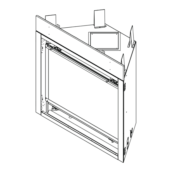
Page 60: Reference Materials
2 1/2 in. 2 1/8 in. (171 mm) 6 5/8 in. (38 mm) (64 mm) (54 mm) (168 mm) 13 1/8 in. (333 mm) 23 3/8 in. (594 mm) Figure 17.1 Appliance Dimensions Heatilator • Evolution • 4065-114 Rev. X • 9/15... - Page 61 DF-MR30/DF-MR30-SS DECORATIVE FRONTS (BOTTOM OF APPLIANCE) 1-1/2 6-1/2 NEVO3630i DF-MR36/DF-MR36-SS DECORATIVE FRONTS (BOTTOM OF APPLIANCE) 1-1/2 6-1/2 NEVO4236i 1067 Figure 3.2 Decorative Front Dimensions (Including Surround) Heatilator • Evolution • 4065-114 Rev. X • 9/15...
-
Page 62: Vent Components Diagrams
(38 mm) (254 mm) 8 in. (203 mm) 14 in. (356 mm) 12 in. (305 mm) 5 in. (127 mm) DVP-WS DVP-HVS Wall Shield Firestop Vent Support Figure 17.2 DVP Vent Components Heatilator • Evolution • 4065-114 Rev. X • 9/15... - Page 63 Cap Shield DVP-TRAPFL Flashing 13-7/8 in. 9-1/2 in. (352 mm) (241 mm) 26 in. (660 mm) 14 in. (356 mm) DVP-HSM-B DRC-RADIUS Extended Heat Shield Cap Shield Figure 17.3 DVP Vent Components Heatilator • Evolution • 4065-114 Rev. X • 9/15...
- Page 64 (305 mm) DVP-FBHT 7-1/8 in. 12-1/8 in. Fire Brick Termination Cap (181 mm) (314 mm) 8-3/4 in. (222 mm) 1-5/8 in. (41 mm) DVP-HPC High Performance Cap Figure 17.4 DVP Vent Components Heatilator • Evolution • 4065-114 Rev. X • 9/15...
- Page 65 117 mm 12 in. 5-3/8 in. 9-3/8 in. Trap2 Effective (305 mm) 137 mm 238 mm Length DVP-TRAP Horizontal Termination Cap DVP-TRAP1 DVP-TRAPK1 DVP-TRAP2 DVP-TRAPK2 DVP-HPC1 DVP-HPC2 Figure 17.5 DVP Vent Components Heatilator • Evolution • 4065-114 Rev. X • 9/15...
- Page 66 5-1/2 in. 8-3/8 in. 5-3/4 to 8-3/8 in. 140 mm 213 mm 146 to 213 mm 3° 87° 10-1/2 in. 267 mm 10-7/8 in. 276 mm DVP-HRC-ZC-SS Figure 17.6 DVP Vent Components Heatilator • Evolution • 4065-114 Rev. X • 9/15...
- Page 67 26 in. (660 mm) SLP-HVS DVP-HSM-B Horizontal Pipe Extended Heat Shield Support SLP-FS SLP-WS SLP-DCF-BK SLP-WT-BK Ceiling Firestop Wall Shield Firestop Decorative Ceiling Wall Thimble-Black Firestop-Black Figure 17.7 SLP Series Vent Components Heatilator • Evolution • 4065-114 Rev. X • 9/15...
- Page 68 (This termination cap requires an SL-2DVP adapter when used with SLP Pipe) SLP-TRAP2 SLP-TRAP1 Horizontal Horizontal Termination Cap Termination Cap 8-1/8 in. 13 in. (206 mm) (330 mm) 15 in. (381 mm) SLP-HRC-SS Figure 17.8 SLP Series Vent Components Heatilator • Evolution • 4065-114 Rev. X • 9/15...
- Page 69 4 3/4 in. Trap1 79 mm 121 mm 12 in. 5 1/4 in. 9 1/4 in. Trap2 Effective (305 mm) 133 mm 235 mm Length SLP-TRAP Horizontal Termination Cap Figure 17.9 Vent Components Heatilator • Evolution • 4065-114 Rev. X • 9/15...
- Page 70 Note: A PVLP-HS heat shield is available and sold 100 FT PV Wire Harness PVI-WH100 separately. Use if the PVLP-SLP is installed in a high traffi c area. PVLP-HS PVLP-BEK Heat Shield Brick Kit Figure 17.10 PVLP-SLP Vent Components Heatilator • Evolution • 4065-114 Rev. X • 9/15...
-
Page 71: Service Parts
Pre Aug 2013 25844 Intake Cover Plate Post Aug 2013 2166-450 Intake Cover Gasket 4031-239 Clear Media Rock 4065-111 Top Vent Flue Baf e 4045-203 Additional Service Parts on following page. 9/15 Heatilator • Evolution • 4065-114 Rev. X • 9/15... - Page 72 Pre Aug 2013 25844 Intake Cover Plate Post Aug 2013 2166-450 Intake Cover Gasket 4031-239 Clear Media Rock 4065-111 Top Vent Flue Baf e 4045-203 Additional Service Parts on following page. 9/15 Heatilator • Evolution • 4065-114 Rev. X • 9/15...
- Page 73 593-528 Pilot Ori ce LP 593-527 Regulator NG NGK-DXV-50 Regulator LP LPK-DXV-50 **Fuse for battery pack can be sourced locally, not a warranty item. Specs are 250v, 1A fuse, 3/4" long Heatilator • Evolution • 4065-114 Rev. X • 9/15...
- Page 74 NGK-DXV-50 Regulator LP LPK-DXV-50 NEVO4236I Conversion Kit NG Conversion Kit LP DCKVP-NEVO4236 Pilot Ori ce NG 593-528 Pilot Ori ce LP 593-527 Regulator NG NGK-DXV-50 Regulator LP LPK-DXV-50 Installation Manual 4065-114 Heatilator • Evolution • 4065-114 Rev. X • 9/15...
-
Page 75: Optional Components
12.5 15.5 LDS-BV Catalog # 20 in. LDS33 [508 mm] LDS46 1219 1829 17 in. [432 mm] 9-3/8 in. [238 mm] LDSCP-M Shroud Leg Multipack (not shown) TCG375 Terra Cotta Cap Heatilator • Evolution • 4065-114 Rev. X • 9/15... -
Page 76: Contact Information
E. Contact Information Please contact your Heatilator dealer with any questions or concerns. For the location of your nearest Heatilator dealer, please visit www.heatilator.com. Heatilator, a brand of Hearth & Home Technologies 7571 215 Street West, Lakeville, MN 55044 www.heatilator.com...
Need help?
Do you have a question about the NEVO4236I and is the answer not in the manual?
Questions and answers