
Related Manuals for CTC Union CTC 380 IC


Summary of Contents for CTC Union CTC 380 IC
- Page 1 162 105 11-1 2013-05-21 Providing sustainable energy solutions worldwide Installation- and maintenance instruction CTC 380 IC Oil condensing boiler unit Models 17/19/24/29...
- Page 3 162 105 11-1 2013-05-21 CTC 380 IC Models 17/19/24/29...
-
Page 5: Table Of Contents
Safety limit thermostat (STB) ......16 Boiler cleaning ..........42 Wiring diagram E-582450 ......17 Spiro-Condense system cleaning ....42, 43 Plant diagrams ..........18 Drainage ............44 Oil operation ..........44 Faults .............44 Declaration of conformity ..........45 Burner manual at the latter part of this folder CTC 380 IC... - Page 6 CTC 380 IC...
-
Page 7: Introduction
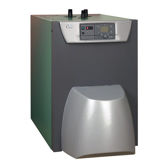
1. Introduction 1.1 General information • CTC 380 IC is a 3-stroke oil condensing boiler unit which meets the progressive demands on profitability, convenience and environmental sustainability. • CTC 380 IC was designed to minimise polluting emissions. • CTC 380 IC is available in six sizes from 18 to 45 kW. -
Page 8: Important Points
2.1. Important points The following important points must be checked during installation: • Unpack CTC 380 IC on delivery and check whether the product was not damaged in transit. • Any transport damage must be reported to t he supplier (carrier). -
Page 9: Technical Data
3. Technical data 3.1 Technical data CTC 380 IC Rated input 17,8 19,7 24,5 29,3 Rated output 50/30 °C 18,2 20,1 25,0 29,9 Rated output 80/60 °C 17,2 19,0 23,7 28,3 Oil supply 1190 1330 1680 2030 Flue gas mass flow rate... -
Page 10: Measurements
9c. Power pack Siemens AVS16.290 Ytjämnhet RA 4. Return flow R 1” 10. Levelling feet M10 5. Expansion connection R 1” 13. Rear cover plate – spiral finned tube 6. Drainage connection R 1” 14. Top cover plate – spiral finned tube Skala 7. Flue gas outlet ø 100 mm inside 8. Condensation water drainage ø50 outside Om ej annat angiv Material CTC 380 IC Ritad Sign. 2007-08-27 Datum... -
Page 11: Description
The operating unit of the comfort control – Siemens AVS37.294. For further information, please refer to Section Electric installation – comfort control separate attached instructions. 13. Oil burner For further information, please refer to Section Oil burner. 14. Hood The hood is an integrated, nicely shaped component of the boiler. CTC 380 IC... - Page 12 Maintenance of the siphon must be performed annually. After the maintenance of the siphon, it must be filled with water. If fitting a neutralisation system is required, the country-specific regulations must be observed. Boiler Condensation water drainage min 26,5 mm CTC 380 IC Distr till/Antal...
-
Page 13: Installation
After removing the packaging, check whether the boiler was damaged during transit. Any transport damage must be report- ed to the supplier (carrier). Standard delivery: Oil condensing boiler unit CTC 380 IC ◗ Cleaning tools ◗... -
Page 14: Boiler Room
3 bar. The hydraulic connection between boiler and safety valve must be designed so that no increase in pressure is possible. The overflow pipe must be free and visible. Any escaping heating water must be drained without danger. (Warning! Risk of scalding). CTC 380 IC... -
Page 15: Heating Circulation Pump
4.14 Connection of domestic water heater (storage) If the CTC 380 IC is combined with a domestic hot water heater, it must be ensured that its size and capacity correspond to the installed boiler capacity. The connection must comply with the applicable construction law regulations. Usually to be connected to the rear flow and return connections of the boiler. -
Page 16: Electric Installation
5.4 Safety temperature limiter (STB) For extremely cold storage of the boiler, the safety temperature limiter can be initiated. It is restored with the button at the front of the power pack. STB restore button CTC 380 IC... -
Page 17: Wiring Diagram E-582450
6.3 AT Sicherung 6,3 AT power pack with glowing light STB safety temperature limiter 110°C Netzschalter mit Glimmlampe signal light, STB-locked STB Shutztemperaturbegrenzer 110 C Signalleuchte, STB verriegelt Ämnes nr CTC 380 IC Distr till/Antal Ersätter Ytjämnhet RA Tol.system art. nr... -
Page 18: Plant Diagrams
5.6 Plant diagrams The applications are displayed as basic diagrams with additional functions. The basic diagrams are possible applications which can be implemented without multiple function outputs. RVS43.143 basic diagram Standard diagram Standard diagram Drinking water with diversion valve CTC 380 IC... -
Page 19: General Information
Part 6. describes the principal information concerning the Comfort-control. Fore more information concerning functions, programming, system principles etc., please see the Albatros2 Boiler Controller User Manual. 6.2 Basic unit RVS43.143 6.2.1 Terminal markings 050110A RVS43.143/109 000020 S050110000020 1PRVS13.143/109 CTC 380 IC... - Page 20 DHW charging pump / diverting valve Neutral conductor AGP8S.03B/109 Protective earth 1st heating circuit pump 1st heating circuit mixing valve opening AGP8S.04B/109 Neutral conductor Protective earth 1st heating circuit mixing valve closing Neutral conductor AGP8S.03C/109 Protective earth 1st multifunctional output CTC 380 IC...
-
Page 21: Checking The Led
AGP4S.02F/109 Ground Flow sensor AGP4S.02G/109 Ground Multifunctional sensor input 1 AGP4S.02F/109 Ground Multifunctional sensor input 2 AGP4S.02F/109 Ground 6.2.2 Checking the LED LED off: No power supply LED on: Ready to operate LED fl ashes: Local faults CTC 380 IC... -
Page 22: Power Pack Avs16.290
Neutral conductor blue Phase AC 230 V burner black S3 Input burner fault Fuse 6,3AT Mains switch with green glow lamp STB Safety limit thermostat (SLT) 110°C Signal lamp (STB tripped) L1 S3 1 2 3 4 5 CTC 380 IC... -
Page 23: Operator Unit Avs37.294
Heating to the frost protection setpoint Heating function temporarily off ECO function activ Holiday function active Process running - please wait Change battery Reference to heating circuit Burner in operation (only oil/gas burner) Maintenance / special mode Error messages CTC 380 IC... -
Page 24: Change Language
Characteristics of continous operation: − Heating mode with no time program − Protective functions active − Automatic summer / winter changeover (ECO functions) and 24-hour heating limit inactive in the case of continuous operation with Comfort setpoint CTC 380 IC... -
Page 25: Selecting Dhw Heating Mode
For the Reduced setpoint - Press the OK button - Choose operating page ”Heating circuit” and - Adjust the ”Reduced setpoint”. Each time you make a readjustment, wait at least 2 hours, allowing the room temperature to adapt. CTC 380 IC... -
Page 26: Displaying Information
In this case, press the Info button to obtain more information. AUTO AUTO Error Fehler Wartung Maintenance 30:Vorlauffühler 1 30:Flow sensor 1 3:Wartungsintervall Text3 Text4 3:Maintenance interval Text3 Text4 CTC 380 IC... -
Page 27: Reset Function
If released, the test will be aborted. The STB test is shown on the display. The test must be made by qualifi ed staff since the boiler temperature will be raised above the maximum limitations. CTC 380 IC... -
Page 28: Programming
“Time of day and date“ appears. Turn the setting knob until operating line Time of day and date “Hours / minutes“ appears. Hours / minutes To confi rm, press the OK button. CTC 380 IC... - Page 29 Month / day Minutes 0...60 min Wireless Year Time program heating circuit 1 Start of summer time Time program heating circuit 2 End of summer time Time program heating circuit P Holidays heating circuit 1 Diagnostics of consumers CTC 380 IC...
-
Page 30: User Levels
Turn the setting knob until the required user level is reached. Enduser Text3 Commissioning Press the OK button. AUTO You are now on the required user level. Time of day and date Text3 Operator section To reach the OEM level, enter the relevant code. CTC 380 IC... -
Page 31: User Levels
Year Time program heating circuit 1 Start of summer time Hours 1...24 h Time program heating circuit 2 End of summer time Minutes 0...60 min Time program heating circuit P Holidays heating circuit 1 Diagnostics of consumers CTC 380 IC... -
Page 32: Commissioning
“Input/output test“ and go through all available operating lines. Operating state The current operating state can be checked on operating page “State“. Diagnostics For detailed diagnostics of the plant, check operating pages “Diagnostics heat source“ and “Diagnostics consumer”. CTC 380 IC... -
Page 33: Time Programs
- It is possible to select 3 phase for each day. - Press “ESC” and “ESC” again. All time programs can be reset to the default settings. Each time program has its own operating line to make this reset. In that case, individual settings will be lost! CTC 380 IC... -
Page 34: Heating Curve
- Select Menu 720 “Heating curve slope” and press “OK” - Select setpoint and press “OK” for confi rm - Select Menu 721 “Heating curve displacement” and press “OK” - Select setpoint and press “OK” for confi rm - Press “ESC” and “ESC” again CTC 380 IC... -
Page 35: Flow Temperature Limitation
- Select a temperature for min fl ow temp, and press “OK” to confi rm. - Select “Flow temp setpoint max” (Menu 741) and press “OK” - Select a temperature for max fl ow temp, and press “OK” to confi rm. - Press “ESC” and “ESC” again. CTC 380 IC... -
Page 36: Domestic Hot Water Dhw
- Select “Confi guration” and press “OK”. - Select “Reset to default parameters” (Menu 6205) and press “OK”. - Select “Yes” and press “OK”. - Press “ESC” and “ESC” again. Selection for Date, Time and Time programs will not be restored. CTC 380 IC... -
Page 37: List Of Displays
BSB radio communication fault Extension module 1 fault (common fault status message) Extension module 2 fault (common fault status message) 2 clock time masters (LPB) Clock time master without backup (LPB) Maintenance message Boiler temperature supervision Lockout by SLT CTC 380 IC... - Page 38 Extension module / mixing valve group same function Sensor BX1 no function Sensor BX2 no function Sensor BX3 no function Sensor BX4 no function Sensor BX5 no function Sensor BX21 no function Sensor BX22 no function Sensor BX1 no function Sensor BX12 no function CTC 380 IC...
-
Page 39: Oil Burner
7. Oil burner 7.1 General information CTC 380 IC is equipped with an adjusted oil unit burner. The start, settings and main- tenance of the burner may be performed by a heating specialist only and in compliance with the operating instructions of the burner (see section Oil burner). -
Page 40: First Start - Commissioning
6. the tapping points of the house are provided with hot water as the boiler has turned warm. 7. the function of the safety valve is faultless. 8. the boiler and the heating system are well vented. Re-check after a few days. CTC 380 IC... -
Page 41: Operation
Never activate the boiler if it is suspected that the boiler or parts pf the heating system may have frozen. This results in damage to the boiler and the pipes in the house. Consult your heating installer. Regards protective operation, see Section Electric installation – comfort control. CTC 380 IC... -
Page 42: Boiler Cleaning
The boiler must be disconnected from the mains when cleaning it. Standard cleaning - once a year in connection with maintenance (regular checks, boiler cleaning, etc.) recommended: 1. Deactivate operating switch. 2. Remove rear cover plate. CTC 380 IC... - Page 43 8. Mount flue gas heat exchanger and couplings 9. Open locking valves and fill boiler. 10. Check whether all pipe connections are waterproof, tighten if required. 11. Mount heat insulation and cover plate. 12. Activate operating switch. CTC 380 IC...
-
Page 44: Drainage
Hot water temperature unsatisfactory: • Check the settings of the comfort control. See Electric installation – Comfort control. If all above mentioned checking measures to clear the fault prove insufficient, please contact your responsible heating specialist company or CTC. CTC 380 IC... - Page 45 CTC 380 IC...
- Page 47 178 066 35-1 2012-01-20 Installations- og driftsvejledning Oliebrænder BF1 CTC 380IC17 CTC 380IC19 CTC 380IC24 CTC 380IC29...
- Page 48 Contents 1. GENERAL ..........................4 1.1 Warnings ................................4 2. TECHNICAL DATA ........................5 2.1 Model BF1 M1V 87-20/BF1 M1V 87-24 ......................5 2.2 Description ..............................6 2.2.1 Components................................7 2.3 Declaration of concordance/conformity ......................8 3. INSTALLATION ........................9 3.1 Oil supply .................................9 3.2 Burner installation ............................9 3.2.1 Oil pipes ..................................9 4.
- Page 49 7. PREHEATER ..........................20 7.1.1 Function FPHB 5-LE ..............................20 7.1.1.1 LE-valve ....................................20 8. ELECTRICAL EQUIPMENT (380IC 17/19) ................21 8.1 Wiring diagram LMO14.113 ..........................21 8.1.1 Component list .................................22 8.1.2 Function LMO14.113..............................22 8.1.3 Technical data ................................22 9. ELECTRICAL EQUIPMENT (380IC 24/29) ................23 9.1 Wiring diagram SATRONIC TF 834E/TF 834E.2/TF834E.3.................23 9.1.1 Component list................................24 9.1.2 Function Satronic ..............................24...
-
Page 50: General
1. GENERAL 1.1 Warnings - The manual must be read before installation and start-up. - This manual should be followed by anyone who for any reason performs work on the installation or its component parts. - The manual is to be considered as part of the burner and must always be kept in the vicinity of the installation site. -
Page 51: Technical Data
2. TECHNICAL DATA 2.1 Model BF1 M1V 87-20/BF1 M1V 87-24 14-16 19-21 Factory setting Boiler Burner Burner Output Nozzle assembly Oil pressure Nozzle CTC 380IC17 BF1M1V 87-20 17,8 10,8 0,40x80°S CTC 380IC19 BF1M1V 87-20 19,7 11,4 0,45x80°S CTC 380IC24 BF1M1V 87-24 24,5 10,2 0,55x80°S... -
Page 52: Description
2. TECHNICAL DATA 2.2 Description... -
Page 53: Components
2. TECHNICAL DATA 2.2.1 Components 1. Brake plate 2. Ignition cable 3. Fan housing, front 4. Ignition transformer 5. Separating screw 6. Eldningsautomat Electrical contact X1 (refer to wiring diagram) 8. Motor 9. Capacitor 10. Ignition electrode 11. UV-detector 12. Inspection glass 13. -
Page 54: Declaration Of Conformity
Försäkran om överensstämmelse Declaration of conformity Konformitätserklärung Déclaration de conformité Brännare, Burner, Ölbrenner, Brûleur Certifi kat TÜV Süddeutschland Certifi kat nr. Typ, Type: Certifi kat nr. Typ, Type: 08128915006 BF 1 02119815003 B 20, B 30, B 40, B 45 0111110535004 02119815004 B 50, B 60, B 70, B 80... -
Page 55: Installation
3. INSTALLATION 3.1 Oil supply In order to achieve good operational reliability it is important that the oil supply system is laid out correctly. Observe the following: - Choice of pipe diameters, pipe lengths and height differences (refer to pump instructions). - Piping should be run with a minimum of joints/compression fi ttings. -
Page 56: Basic Settings
4. BASIC SETTINGS The burner is fi tted with a regulator which changes the brake plate position 4.1.1 Nozzle assembly adjustment in the blast tube. This is used to set the amount of recirculation to obtain a good combustion without pulsations. The best setting for achieving low emissions is, among other things, dependent on the output settings and overpressure in the boiler. -
Page 57: Burner Servicing
5. BURNER SERVICING 5.1 Warning Service must be carried out after 3,000 operating hours, or at least once per year. Only authorized personnel may perform service. Before any type of service work is begun, switch of the power at the main Warning switch and shut off the oil. -
Page 58: Oil Pump Replacement
5. BURNER SERVICING 5.1.3 Oil pump replacement 1. Switch off the power at the main switch and disconnect the Eurostecker 2. Disconnect the oil hoses from the oil pump. 3. Remove the screw securing the burner to the fl ange on the boiler. Draw out the burner head. Take care as this can become very hot. 4. -
Page 59: Air Intake And Intake Cone Service
5. BURNER SERVICING 5.1.5 Air intake and intake cone service 1. Switch off the power at the main switch and disconnect the Eurostecker from the burner. 2. Remove the screw securing the burner to the fl ange on the boiler. Draw out the burner head. Take care as this can become very hot. 3. -
Page 60: Cleaning, Alternative 1
5. BURNER SERVICING 5.1.6.2 Cleaning, alternative 1 1. Switch off the power at the main switch and disconnect the Eurostecker from the burner. 2. Remove the screw securing the burner to the fl ange on the boiler. Draw out the burner head. Take care as this can become very hot. 3. -
Page 61: Cleaning, Alternative 2
5. BURNER SERVICING 5.1.6.3 Cleaning, alternative 2 1. Switch off the power at the main switch and disconnect the Eurostecker from the burner. 2. Remove the screw securing the burner to the fl ange on the boiler. Draw out the burner head. Take care as this can become very hot. 3. -
Page 62: Replacement Of Complete Electrical Package
5. BURNER SERVICING 5.1.7.1 Replacement of complete electrical package 1. Switch off the power at the main switch and disconnect the Eurostecker from the burner. 2. Remove the screw securing the burner to the fl ange on the boiler. Draw out the burner head. Take care as this can become very hot. 3. -
Page 63: Pump Instructions
6. PUMP INSTRUCTIONS 6.1 Danfoss BFP 21LE-S 6.1.1 Technical data Viscosity range: 1,3–12,0 mm Pressure range: 7–15 bar Oil temperature: –10 to +70°C 6.1.2 Components 1. Pressure regulation 2. Manometer connection G 1/8” 3. Filter 4. Solenoid valve 5. Nozzle connection G 1/8” 6. Vacuum manometer connection G 1/8” Horseshoe washer/Return plug 8. -
Page 64: Function Bfp 21Le-S
6. PUMP INSTRUCTIONS 6.1.4 Function BFP 21LE-S When the pump is started oil is drawn from the suction connection (S) through the fi lter (H) to the gear wheel pump’s suction side (C). From there the oil is conveyed to the pressure side of the gear wheel pump, where the oil is pressurized. The pressure is controlled and held constant at a set value by the regulator valve (P ) via the membrane (D). -
Page 65: Suction Pipe Tables Bfp21Le-S
6. PUMP INSTRUCTIONS 6.1.7 Suction pipe tables BFP21LE-S 6.1.7.1 Overhead Tank One-pipe system Height m Line diameters ø 4 mm ø 5 mm ø 6 mm Two-pipe system Height m Line diameters ø 6 mm ø 8 mm ø 10 mm 6.1.7.2 Underlying Tank One-pipe system For reliable operations, use of a Tigerloop is recommended in underlying... -
Page 66: Preheater
7. PREHEATER When the boiler thermostat connects, the PTC element is energized and 7.1.1 Function FPHB 5-LE oil begins to preheat. When the oil has reached the correct temperature, the preheater thermostat closes and the burner receives the start signal. During operations the PTC element compensates its output so that the temperature does not become too high. -
Page 67: Electrical Equipment (380Ic 17/19)
8. ELECTRICAL EQUIPMENT (380IC 17/19) 8.1 Wiring diagram LMO14.113 Boiler... -
Page 68: Component List
8. ELECTRICAL EQUIPMENT LMO14.113 (380IC 17/19) 8.1.1 Component list Oil burner control Ignition transformer Preheater Solenoid valve M1 Burner motor Plug-in contact, burner R1 Photocell QRB X2 Plug-in contact, boiler U2 UV-Detector QRC Preheater wiring colours: A Blue B Brown C Black The installation must be connected to the mains and fused according to local regulations. -
Page 69: Electrical Equipment (380Ic 24/29)
9. ELECTRICAL EQUIPMENT (380IC 24/29) 9.1 Wiring diagram SATRONIC TF 834E/TF 834E.2/TF834E.3 Boiler... -
Page 70: Component List
9. ELECTRICAL EQUIPMENT SATRONIC (380IC 24/29) 9.1.1 Component list Oil burner control Ignition transformer Preheater Solenoid valve Fuse, max. 10A Plug-in contact, burner Burner motor Plug-in contact boiler Preheater wiring colours: A Blue B Brown C Black The installation must be connected to the mains and fused according to local regulations. -
Page 71: Application
9. FLAME SUPERVISION FOR OIL BURNER CONTROL (380IC 24/29) 9.1.4 Application The fl icker detector IR 911/IR 1010 is used for the supervision of the oil fl ame and is connected to a Satronic oil or gas burner control. The su- pervision function is based on the infra red fl icker principle, i.e. only infra light is sensed and it does not react to the even radiation from the brick lining, if any, in the boiler. 9.1.5 Technical Data Ambient temperature: -20...+60°C... -
Page 72: Fault Location
10. FAULT LOCATION 10.1 Burner will not start Symptom Causes Remedies Motor starts Unstable fl ame Burner pre-ventilates Excess air Adjust the damper Low oil pressure Check the oil pressure Flame formed Incorrect combustion apparatus settings Check the nozzle in relation to the combustion apparatus dimensions and Burner trips the ignition electrode position... - Page 76 Enertech AB. P.O Box 309 SE-341 26 Ljungby Sweden. www.ctc.se, www.ctc-heating.com...
Need help?
Do you have a question about the CTC 380 IC and is the answer not in the manual?
Questions and answers