
Related Manuals for CTC Union 950


Summary of Contents for CTC Union 950
- Page 1 161 505 10-1 Art.no 580090002/3 Eng. Feb -03 Providing sustainable energy solutions worldwide Installation- and maintenance instruction CTC 950 Wall mounted oil-/gas-fired unit...
- Page 3 Art.no 580090002/3 Eng. Feb -03 Installation and maintenance CTC 950 Wall mounted oil-/gas-fired unit...
- Page 4 161 505 10 03-01...
-
Page 5: Table Of Contents
01. Technical data 1.1 General description..............4 1.2 Technical data................4 1.3 Construction..................5 02. Installation CTC 950 2.1 With one heating circuit without hot water.......6,7 2.2 With hot water tank and one heating circuit......8,9 2.3 With hot water tank and two heating circuits.......10,11 2.4 With heat exchanger.............12,13... -
Page 6: Technical Data
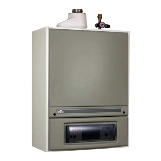
01. TECHNICAL DATA The CTC 950 is a wall mounted oil fired unit. CTC 950 is delivered with 1.1 General description expansion vessel, circulation pump, oil burner, instrument panel and safety valve. CTC 950 combines small dimensions, easy maintenance, extremely low noise level and high efficiency. -
Page 7: Construction
01. TECHNICAL DATA 1.3 Construction Air inlet Automatic Flue outlet air bleeder with sealing Manometer Safety valve 2,5 bar Insulation Cleaning door Expension vessel Baffle plate 4 pcs Baffle plate stainless steel1 pcs Burner Combustion Filling valve chamber only when at exchanger version Pump... -
Page 8: With One Heating Circuit Without Hot Water
02. INSTALLATION 2.1. CTC 950 with one heating circuit without hot water. • Electrical diagram D-580070 Dimensions 1. Flue outlet diam 82 mm internal with high temp sealing diam 80 mm 2. Air inlet hose diam 80 mm internal 3. Flow G 3/4” internal/external 4. - Page 9 02. INSTALLATION 2.1. CTC 950 with one heating circuit without hot water 4(10) 161 145 07 02-01...
-
Page 10: With Hot Water Tank And One Heating Circuit
02. INSTALLATION 2.2 CTC 950 with hot water tank and one heating circuit • Pipe kit (P/N 579990301) 1-circuit, assembly instr. see chapter 06. • Mixing valve (P/N 912912401) • Electrical diagram D-580097. Dimensions 1. Flue outlet diam 82 mm internal with high temp sealing diam 80 mm 2. - Page 11 02. INSTALLATION Examples CTC 950 with hot water tank and one heating circuit 6(10) 161 145 07 02-01...
-
Page 12: With Hot Water Tank And Two Heating Circuits
02. INSTALLATION 2.3 CTC 950 with hot water tank and two heating circuits • 2-circuit pipe kit (P/N 580035301), assembly instr. see chapter 06 • Mixing valve (P/N 912912401) • Electrical diagram D-580097 Dimensions 1. Flue outlet diam 82 mm internal with high temp sealing diam 80 mm 2. - Page 13 02. INSTALLATION Examples CTC 950 with hot water tank and two heating circuits 8(10) 161 145 07 02-01...
-
Page 14: With Heat Exchanger
02. INSTALLATION 2.4 CTC 950 with heat exhanger and one heating circuit • Heat exhanger cpl (579970301) • Mixing valve (912912401) • Hot water priority relay (580166402) • Electrical connection acc. to: - with mixing valve and DHW priority relay: electrical diagram (D-580098) - Page 15 02. INSTALLATION 2.4 Examples CTC 950 with heat exhanger and one heating circuit With mixing valve. Note: DHW priority relay (580166402) must be installed Without mixing valve. 10(10) 161 145 07 02-01...
-
Page 16: Electrical Installation 3.1 General Information
03. ELECTRICAL INSTALLATION The electrical installation must be made according to current regulations. 3.1 General information In particular, there must be a proper connection to an efficient ground system Have the electrical installation and system checked by professionnally Check qualified electricians, who certify that the electrical installations correspond to current regulations. -
Page 17: Electrical Diagram D-580070
Main switch for boiler Control thermostat TÜV switch Fuse Lamp safety thermostat Eurostecker for burner Lamp burner fault Terminal block (regulation) Switch for burner Micro switch heat exchangr (option) Switch for circulation pump PUMP Pump for radiator system, if cable is on no 7. -
Page 18: Electrical Diagram D-580097
Control thermostat Main switch for boiler Fuse8 TÜV switch Eurostecker for burner Lamp safety thermostat Lamp burner fault Terminal block (regulation) Micro switch heat exchangr (option) Switch for burner PUMP Pump forhot water tank Switch for circulation pump Signal on terminal No 9 will start the pump for hot water tank Safety thermostat... -
Page 19: Electrical Diagram D-580098
Main switch for boiler Control thermostat Fuse TÜV switch Eurostecker for burner Lamp safety thermostat Terminal block (regulation) Lamp burner fault Switch for burner Micro switch heat exchanger PUMP Pump for heat exchanger Switch for circulation pump Safety thermostat... -
Page 20: Operation
04. OPERATION 4.1 Control panel 1. Main switch for boiler 7. Boiler thermometer Connects / Disconnects the electrical power to Shows the boiler water temperature the boiler. Indicates with green color when power is on. 8. Fuse 6,3 A Open the fuse holder by using a screwdriver to dismantle the top 2. -
Page 21: Start-Up
04. OPERATION -Check that the boiler and radiator system are filled with water. 4.2 Start-up - Vent the boiler by opening by hand the safety valve on the top of the boiler. Make a subsequent filling of the system when needed. - Check that all tube connections are tight and that the connections for chimney and combustion are correctly performed. -
Page 22: Assembly Instruction Boiler
05. ASSEMBLY INSTRUCTION BOILER 1(7) 161 345 03 02-01... - Page 23 05. ASSEMBLY INSTRUCTION BOILER 2(7) 161 345 03 02-01...
-
Page 24: Assembly Instruction Pipe Kit
06. ASSEMBLY INSTRUCTION PIPE KIT 6.1 Assembly instruction pipe kit (579990301) 3(7) 161 345 03 02-01... -
Page 25: Pipe Kit (580035301)
06. ASSEMBLY INSTRUCTION PIPE KIT 6.2 Assembly instruction pipe kit (580035301) 4(7) 161 345 03 02-01... -
Page 26: Assembly Instruction Heat Exchanger (579970301)
07. ASSEMBLY INSTRUCTION HEAT EXCHANGER (579970301) 5(7) 161 345 03 02-01... - Page 27 07. ASSEMBLY INSTRUCTION HEAT EXCHANGER (579970301) 6(7) 161 345 03 02-01...
-
Page 28: Assembly Instruction Hot Water Priority Relay (580166402)
08. ASSEMBLY INSTRUCTION HOT WATER PRIORITY RELAY (580166402) Must be used when using heat exchanger and mixing valve. Connect acc to Electrical diagram D-580098 7(7) 161 345 03 02-01... -
Page 29: Service Oil Burner
09. SERVICE OIL BURNER 1(3) 161 425 04 02-01... -
Page 30: Service Boiler
10. SERVICE BOILER 2(3) 161 425 04 02-01... -
Page 31: Service Check And Electrical Installation
11. SERVICE CHECK AND ELECTRICAL INSTALLATION 1. Turn the safety valve a few times a year 2. A space in the front part of the boiler is provided in to check the operation of the safety valve. the cleaning door to proceed to measurements. 3. -
Page 32: Chimney Solutions
12. CHIMNEY SOLUTIONS The installation must be performed according to the local regulations. 12.1 Balanced flue system 80/125 We reccomend to use the chimney solution according to figure A if possible. Max 3 meter 1(2) 161 365 05 02-01... -
Page 33: Separate Flue Outlet (80 Mm) And Air Inlet (80 Mm)
12. CHIMNEY SOLUTIONS 12.2 Separate flue outlet (80 mm) The installation must be performed accordingly to local regulations. and air inlet (80 mm) Max 3 meter 2(2) 161 365 05 02-01... - Page 36 Enertech AB. P.O Box 309 SE-341 26 Ljungby Sweden. www.ctc.se, www.ctc-heating.com...
Need help?
Do you have a question about the 950 and is the answer not in the manual?
Questions and answers