Table of Contents
Advertisement
Installation & Servicing Instructions
60B
75B
Balanced Flue Boilers
One Contact Total Service
Supplied By www.heating spares.co Tel. 0161 620 6677
To b e l e f t w i t h t h e u s e r
G.C. No. 41 319 04
G.C. No. 41 319 62
This is a Cat I
Customer Services:
Tel: (01773) 828100
Fax: (01773) 828070
With Honeywell Control
Appliance
2H
Hepworth Heating Ltd.,
Nottingham Road, Belper, Derbyshire. DE56 1JT
General/Sales enquiries :
Tel: (01773) 824141 Fax: (01773) 820569
220459C.03.96
BS6332
BS5258
Advertisement
Table of Contents

Related Manuals for Glow-worm Economy Plus 41 319 04


Summary of Contents for Glow-worm Economy Plus 41 319 04
- Page 1 220459C.03.96 Installation & Servicing Instructions To b e l e f t w i t h t h e u s e r G.C. No. 41 319 04 G.C. No. 41 319 62 Balanced Flue Boilers With Honeywell Control BS6332 This is a Cat I Appliance BS5258...
-
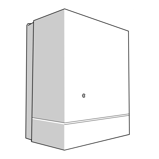
Page 2: Overall Dimensions
1 General 2401 FLOW RETURN WATER WATER CONNECTIONS CONNECTIONS FLUE CONNECTION CONNECTION OVERALL DIMENSIONS Given in millimetres Diagram 1.1 Sheet Metal Parts The instructions consist of two parts Installation and Servicing Instructions and Instructons for Use which WARNING. When installing or servicing the boiler care includes the Guarantee Registration Card. -
Page 3: Statutory Requirements
1 General 1.1 Statutory Requirements 1.3 Range Rating This boiler must be installed by a competent person in This boiler is range rated and may be adjusted to suit accordance with the requirements of the current issue of: individual system requirements. The Gas Safety (Installation and Use) Regulations, Table 1 gives the ratings and settings. - Page 4 1 General 1.5 Gas Supply ECONOMY PLUS 60B Table 1 The gas installation shall be in accordance with the Min. Med. Max. RANGE RATING current issue of BS6891. NOMINAL 18.47 22.00 The supply from the governed meter must be of HEAT Btu/h INPUT...
- Page 5 1 General 1.9 Draining Tap Any electrical switch or boiler control using mains electricity should be so fitted that it cannot be touched by A draining tap must be provided at the lowest points of a person using the bath or shower. The electrical the system which will allow the entire system, boiler and provisions of the Building Standards (Scotland) hot water cylinder to be drained.
- Page 6 2 Flue and Ventilation 2.3 Wall Thickness AIR VENT AREA TABLE FOR COMPARTMENT INSTALLATIONS Check the thickness of the wall. The standard flue set supplied is suitable for wall TABLE 2 AIR VENT AREAS thickness 238mm to 330mm. For other wall thickness, a short flue kit No.443239 for 76mm to 238mm and a long POSITION AIR FROM...
- Page 7 3 Water Systems 3.2 Cylinder Open (vented) system. Recommended SINGLE FEED (SELF PRIMING) CYLINDERS ARE relationship between NOT RECOMMENDED. pump, cold feed and 450mm vent. MIN. The hot water cylinder must be a double feed, fully HEIGHT indirect, type. 22 mm (MIN) VENT FEED AND EXPANSION 3.3 Inhibitor...
- Page 8 3 Water Systems 3.4 Safety Valve 3132 METHOD 1 COMBINED A safety valve must be fitted in a sealed water system. CHECK VALVE HEATING TEMPORARY AND VACUUM SYSTEM It shall be preset, nonadjustable with a lift pressure of HOSE BREAKER 3bar, incorporating seating of a resilient material, a test device and a connection for drain.
-
Page 9: Flue And Appliance Preparation
4 Flue and Appliance Preparation 0855 4.1 Positioning Place the template, provided, square on the wall in the required position and mark location of the balanced flue hole, see diagram 4.1. Cut the hole in the wall to accept the wall liner, see diagram 4.1. - Page 10 5 Installation 5.1 External Access Procedure From inside the room fit the already prepared air duct assembly. Attach the self adhesive seal “D” to the terminal wall plate, see diagram 4.2. INNER CASE Place the terminal against the outside wall with the inner SECURING flange of the wall plate located inside the air duct SCREWS (TOP)
-
Page 11: Appliance Preparation
5 Installation 5.3 Appliance Preparation 5.5 Standard and Short Flue Only Remove the controls cover by pulling if forward and off. Push the flue duct “G” into the terminal with the unflanged end entering the terminal. Make sure that the Remove the outer case by undoing the screw at the lower flange of the duct fits behind the combustion bottom and unhooking at the top. -
Page 12: Installation
Installation 5.6 Long Flue Set Only For long flues the flue duct “G”, extension “L” and sleeve “K” need to be assembled together to suit the wall thickness. This assembly is 75mm longer than the air duct assembly already prepared. A minimum overlap of 40mm is required at each joint. -
Page 13: Control Box
6 Gas and Water Connection Connect the gas supply to the Rc gas cock. The whole of the gas installation, including the meter should be inspected, tested for soundness and purged in accordance with the current issue of BS6891. Connect water to the boiler using the nuts and olives supplied to BS2871 copper tube. - Page 14 7 Electrical Wiring BROWN CIRCULATION BLUE PUMP GRN / YELLOW 240~50Hz BROWN PERMANENT BLUE MAINS SUPPLY FUSED AT 3A CHASSIS EARTH GAS VALVE POST N L SL 9 8 SWITCHED CONTROL TIME SWITCH BROWN PROGRAMMER ETC. (if fitted) BLUE PURPLE BROWN Remove Red Link between 9 and SL...
-
Page 15: Boiler Controls
8 Commissioning 8.1 All Systems 8.3 Initial Lighting and Testing Make sure that the system has been thoroughly flushed Refit the outer case, see diagram 5.1. out with cold water without the pump in place. Identify the controls by reference to diagram 8.1. Refit the pump, fill the system with water, ensuring that all air is properly vented from the system and pump. - Page 16 8 Commissioning Fit the outer case, secure with the screws previously 8.6 Adjustment - All Systems removed. When commissioning the system the boiler should first Make sure that the pilot is alight and stable, view be fired with the bypass fully closed on full service, that through window “G”.
-
Page 17: Pilot Assembly
10 Servicing and Replacement of Parts Servicing and replacement of parts must be carried out WING NUT (2) by a competent person. SECURING ANGLE Before commencing a service or replacing parts isolate FLUE HOOD the gas and electrical supplies. Unless stated otherwise replacement of parts is in the HOOK reverse order to removal. - Page 18 10 Servicing and Replacement of Parts Unscrew the thermocouple nut. 14 to 17 mm The pilot burner can now be lifted away. Take care not to damage the electrode. When replacing ensure that the spark gap is as shown in diagram 10.3.
- Page 19 10 Servicing and Replacement of Parts 10.8 Gas Valve 10.12 Thermostat Gain access generally as Section 10.4. Gain access as under Section 10.4. Remove the screw to release the gas valve cover. Remove and support control. See Section 10.9. Disconnect all leads and pipes at the gas valve. Remove the control knob and electrical connections from the thermostat.
- Page 20 11 Fault Finding Fault and Cause Remedy 11.1 Pilot goes out after a period of remaining alight Front cover not fitted correctly Fit parts correctly. Flue parts not fitted or sealed properly. Seal cavity or fit parts flue parts correctly as described in installation instructions.
- Page 21 11 Fault Finding 11.7 Thermocouple and Over Heat Cutoff To test the thermocouple, a meter with a range of 0 to 30mV is required. CONNECTION 'A' Symptoms: The pilot burner fails to stay alight. Test the thermocouple, overheat cutoff and thermocouple connectors, as described in fault finding diagram 11.2 and diagram 11.1.
-
Page 22: Fault Finding
11 Fault Finding ELECTRICAL Ensure that all services are available at the appliance, i.e. Gas, Electricity, Water. With Pilot Lit. Isolate the supply. Gain access to the control box, check all connections etc. Restore supply. Using multimeter set at 240V. Check incoming supply and fuses. -
Page 23: Functional Flow
11 Fault Finding ELECTRICAL continued Continued Continued Faulty Cable (PURPLE) between thermostat Turn ON thermostat; and terminal block, repair or renew. Is there 240V between 7 and N ? Faulty pump, inform customer Does pump run ? With thermostat set to MAX. allow appliance temperature to reach max. -
Page 24: Pilot / Ignition
11 Fault Finding 2839 PILOT WILL NOT LIGHT START HERE Does pilot stay alight when Check gas line-open all cocks, gas valve knob is released? rectify any blockages, purge out any air. Does pilot light? Apply match to pilot burner instead of pressing piezo unit button. -
Page 25: Spare Parts
12 Spare Parts 12.1 Ordering When ordering spare parts, quote the part number, description, serial number and model from the label on the boiler, see diagram 8.1. Diagram 12.1 Key No. Part No. Description G.C. No. 433504 Electrical control box 313 053 900501 Piezo unit... -
Page 26: Control Of Substances Hazardous To Health
Control of Substances Hazardous to Health Information for the Installer and Service Engineer. Under Section 6 of The Health and Safety at Work Act, 1974, we are required to provide information on substances hazardous to health. The adhesives and sealants used in this appliance are cured and give no known hazard in this state. Insulation and Seals Ceramic fibre and glass fibre are used in insulation panels, rope and gaskets. - Page 27 220459C Supplied By www.heating spares.co Tel. 0161 620 6677...
- Page 28 Because of our constant endeavour for improvement details may vary slightly from those given in these instructions. 220459C Supplied By www.heating spares.co Tel. 0161 620 6677...
Need help?
Do you have a question about the Economy Plus 41 319 04 and is the answer not in the manual?
Questions and answers