
Related Manuals for LXNAV LX Zeus 4.3


Summary of Contents for LXNAV LX Zeus 4.3
-
Page 1: Users Manual
LX Zeus LX Zeus LX Zeus 4.3 Users manual (Preliminary) Tkalska 10 SI 3000 Celje Tel.: 00 386 3 490 46 70 Fax.: 00 386 3 490 46 71 support@lxnavigation.si www.lxnavigation.si February 5, 2013 - 1 -... -
Page 2: Table Of Contents
LX Zeus SYSTEM DESCRIPTION .........................- 6 - Hardware concept ........................- 6 - 1.1.1 Rotary switches and push buttons ...................- 7 - 1.1.2 USB and SD port........................- 7 - 1.1.3 Connections ..........................- 7 - Software ............................- 8 - Technical data..........................- 8 - Operation and controls ......................- 8 - 1.4.1 System push buttons (5) ......................- 9 -... - Page 3 LX Zeus 2.2.3.2 Transfer of Turn Point data ...................- 28 - 2.2.3.3 Transfer of Airspace files....................- 28 - 2.2.3.4 Transfer of Zeus config file....................- 28 - 2.2.3.5 Transfer of Flarm net files .....................- 29 - 2.2.3.6 Transfer Maps .......................- 29 - 2.2.3.7 How to delete files (APT, TP, AS) .................- 29 - 2.2.4...
- Page 4 LX Zeus Colibri II Zeus interaction ......................- 44 - 5.4.1 Colibri II Zeus data exchange ....................- 44 - LX Zeus and Flarm ........................- 44 - 5.5.1 Visualisation of Flarm objects ....................- 44 - 5.5.2 Flarm external displays ......................- 45 - REMOTE CONTROL........................- 46 - Remote in second seat ......................- 46 - SECOND SEAT UNIT ........................- 46 -...
- Page 5 LX Zeus ZEUS 4.3 SPECIFIC........................- 57 - February 5, 2013 - 5 -...
-
Page 6: System Description
LX system bus solution. All connections are plug and play that means no exacting works which needs specialists. The manual for LX Zeus and for LX Zeus 4.3 is the same as the units uses the same software. Hardware is also nearly the same. -
Page 7: Rotary Switches And Push Buttons
LX Zeus Commercially available versions: LX Zeus IGC: package consists of LX Zeus Computer, Colibri II flight recorder and USB D 60 • vario unit LX Zeus Flarm: LX Zeus computer with Flarm unit and USB D 60 (IGC Flarm optionally) •... -
Page 8: Software
LX Zeus For instance: Colibri LX 20, VL… If flarm is connected, two Flarm displays can be connected to the system after using of Displ 1 and Displ 2 plugs. SD plug connects SD card slot which is on the front panel with Flarm. -
Page 9: System Push Buttons (5)
LX Zeus 1.4.1 System push buttons (5) button (VARIO/FLARM) VARIO (short press): input of MC, Ballast and Bugs • FLARM (long press): activation of Flarm radar screen • button (TSK/MOVE) TSK . task management, for next actions use press buttons near to the labels •... -
Page 10: Navigation Push Buttons (3)
LX Zeus button (SELECT/NEAR) SELECT: selection of APT, TP and TSK • NEAR : activation of near function (Airport…) • button (SETUP/INFO) SETUP: direct access to Setup menu • INFO. information about system • configuration Main page 1.4.2 Navigation push buttons (3) Three buttons are used to leaf through navigation menus of LX Zeus. -
Page 11: Custom Creation Of Bottom Rows
LX Zeus button (1- 4) 1-4 : LX Zeus uses bottom row for nav boxes presentation. Up to 4 variants are fully custom programmable and selectable by 1-4 push button. Bottom row configuration is a matter of custom design, more see in Setup Layout. Actual bottom row variant Is shown by a number (1-4) which position is in the right... -
Page 12: Bottom Row Layout
LX Zeus 1.4.2.2 Bottom row layout Bottom row can be positioned on the bottom of the display and as well on the top (in fact any position can be chosen). The info row can be used as single row, double or triple row. For more information see Setup/Layout. -
Page 13: Second Navigation Page
LX Zeus Second navigation page 1.4.4 This page shows 3D terrain data regarding to glider present position. “Tunnel” in the middle means glider is on glide. The pilot should 1.5 Rotary switches Both rotary switches are multifunctional, their basic functions are audio volume adjustment and zoom adjustment. -
Page 14: Audio Volume Rotary Switch
LX Zeus Audio volume rotary switch 1.5.1.2 a bar will show audio volume status after rotation. 1.5.1.2.1 Additionally functions The main secondary function of Volume rotary switch is its press function. When pressed in edit mode will execute jump out of the menu. - Page 15 LX Zeus also kept visible or not visible. See Setup/Layout for details. Header Wind Indicators are: header • speed indicator • Vario variometer (bar) Speed ind. • variometer (needle) • wind indicator • final glide indicator • thermal assistant • Final glide compass •...
- Page 16 LX Zeus Header customisation Customisation of header should be done similar way as by bottom row. After a long press on volume the customisation can start. After press on zoom a list of will open. February 5, 2013 - 16 -...
-
Page 17: Setup
LX Zeus 2 Setup Setup menu is available after short press on SETUP labelled push button. The menu is divided into two sections. System settings are settings which are valid for the whole system and couldn’t be pilot specific data. Items connected to pilot may vary from pilot to pilot and depend on pilot individual requirements. Suitable symbols will accompanied with text will help you to find the menu of interest. -
Page 18: Audio Settings
LX Zeus 2.1.2 Audio settings This menu defines audio configuration. Audio generator is a part of Vario unit (USB D 60) but settings are stored in LX Zeus. Speed command mode: -defines audio in SC, there are several variants The most common used setting is Both which means no piep,piep by positive deflections. -
Page 19: Vario Settings
LX Zeus 2.1.4 Vario settings Settings of this menu defines vario characteristics and some other important inputs connected to vario and speed command. Vario: -vario filter defines dynamic of vario needle lover number means faster reaction and vice versa -smart vario* -vario average time (display on vario unit) -vario scale, three options (2.5, 5 and 10 m/s) (5, 10 and 20 kts, if defined in Units) - Page 20 LX Zeus LX Zeus has a connection for an external speed command switch, which is wired to vario unit. Using an external switch it is possible to switch between SC and Vario manually. Setting the SC Switch to ON means that closing of the switch will cause SC mode, and setting SC INPUT to OFF means that closing the switch will select Vario mode.
- Page 21 LX Zeus The TEF (TE filter) is the compensation delay. Larger numbers will increase the delay and vice versa. During the first test is recommended to use TEF 4. Electronic TE is only effective when the pitot and static sources are co-located and the pneumatic lines to the instrument are approximately the same length.
-
Page 22: Indicators
LX Zeus 2.1.5 Indicators Indicator means vario indicator with its mechanical needle and colour graphic display. One indicator is incorporated into USB D 60 vario unit. The system is also capable to drive secondary indicators.Secondary indicators may be simple repeaters or may also indicate different data sets, all depends on indicator address. -
Page 23: Flarm Settings
LX Zeus Secondary indicators Secondary indicators should be connected via 485 system bus. There are three 9P connectors at the back of the unit All contacts are absolutely parallel, so it doesn’t matter which one is occupied. The unit can be also used as 485 system bus splitter. -
Page 24: Airspace Management
LX Zeus 2.1.8 Airspace management All settings connected to AS management are available in this menu. Note! Hide airspace above option will remove airspace sections which are higher than set. This will unload graphic page significant. 1000m Show on zoom, defines appearance of particular airspace sections on the display. -
Page 25: Map Palette
LX Zeus 2.1.10.1 Map palette To adapt map colours regarding to pilot personal requirements use this menu. There are six variants offered. 2.1.10.2 Map Orientation The map orientation of LX Zeus can be used in three different ways as follows: North up •... -
Page 26: Show Flarm Till Zoom
After 30 minutes the back light will go back to default. After press (zoom) on Brightness a change will happen followed by a clear message. Note! Not valid for LX Zeus 4.3, Zeus 4.3 hasn’t brightness adjustment option. February 5, 2013 - 26 -... -
Page 27: System Setup
LX Zeus 2.2 System Setup The parameters set in this section are valid for all pilots and are therefore global. 2.2.1 Units A huge palette of units can be defined in this menu. 2.2.2 Glider (glider polar selection) There are nearly all glider poplars stored in the LX Zeus memory. -
Page 28: Transfer Of Airport Data
LX Zeus 2.2.3.1 Transfer of Airport data LX Zeus is capable to accept airport data in LX Navigation format (.af). The data is available on www.lxnavigation.si. The data base is free and no code is necessary. The airport files include regularly airport data of one continent. -
Page 29: Transfer Of Flarm Net Files
LX Zeus 2.2.3.5 Transfer of Flarm net files Files with extension .fln include Flarm customized IDs. That makes possible to identify gliders in the vicinity with their original IDs (usual comp. numbers). The data are available on http://www.flarmnet.org. 2.2.3.6 Transfer Maps This item makes possible to load terrain data. - Page 30 LX Zeus The procedure: select Layout option in Setup • Note! press zoom on Layout • Changes will check one two or all three (TP,APT,TSK) • happen only on highlight Edit and press zoom • checked items. After press a very significant screen will open;...
-
Page 31: Locale
LX Zeus terminate the process after using of press on volume • (a very significant message will accompany termination) 2.2.5.1.2 Customisation of indicators After a long press (zoom) on any indicator which is equipped with frame following screen will open. Customisation of actual indicator could happen. -
Page 32: Navigation Modes
LX Zeus 3 Navigation modes LX Zeus offers three modes for navigation. The modes are: APT: navigation to Airports which are stored in APT memory • TP : navigation to turn points (TP) • TSK: task navigation after a task has been entered •... -
Page 33: Apt Selection From Near Function
LX Zeus Now you can scroll with Zoom knob or you can use County and Name filters to reduce number of offered airports. After airport of interest is found terminate the process with short press on Zoom. Note! When using Name filter, input the first letters of the airport name. -
Page 34: Navigation In Apt Mode
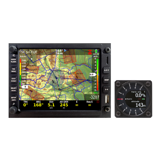
LX Zeus 3.3 Navigation in APT mode There are three navigation pages possible all selectable by SUBP button. 3.3.1 Main graphic navigation page Distance Status indicators Steering com. APT name Variometer bar IAS bar Course line Final glide indicator The bottom row consists of nav boxes, there are four bottom row variants available that means maximal 24 nav boxes can be used. -
Page 35: Third Navigation Page
LX Zeus 3.3.3 Third navigation page The third navigation page shows terrain data in 3D configuration and AHRS if this is a part of the system Note! This page can be disabled after command executed in Setup/User Interface. 3.3.4 Map orientation LX Zeus can work in different map orientation modes as follows: track up •... -
Page 36: Turn Point Mode
LX Zeus 3.4 Turn point mode The structure of the mode is similar to APT, the only important difference is, that the navigation is towards turn points which are included in turn point files. The turn point files (.cup) should be uploaded by USB stick. -
Page 37: Storing Of Actual Position During Flight
LX Zeus 3.4.1.2 Storing of actual position during flight The procedure is identical as described in 3.4.1.1, the only difference is that Lat and Lon input doesn’t matter, as the actual position is already offered. 3.4.2 Selection of a Turn Point The selection process is similar to APT. -
Page 38: Task Mode
LX Zeus 3.5 Task Mode Task is a complex process which guides the pilot around the turn points of the task. Each task consists of turn points, start point and the finish point. Additionally take off and landing can be input, but those points don’t have any influence on task execution. -
Page 39: Task Selection
LX Zeus 3.5.2 Task selection To select task from LX Zeus active task store use Select button and go on with TSK option. Use Zoom knob to select task of interest. During selection process all task relevant data will be present. 3.5.3 Task creation by “hand”... -
Page 40: Creation Of Zones
LX Zeus Creation of Zones 3.5.3.1 ZONE function makes possible to create any known geometry for turn points, start and finish. The creation consists of input of sector angles radius and orientation. Auto next input defines change over philosophy over turn point. AUTO means automatic change over immediatelly after sector will be reached. -
Page 41: Task Restart Function
LX Zeus 3.5.4.1 Task Restart function After task has been started (method doesn’t matter) a task restart can be executed at any time. Use Restart button of TSK menu. Restart button will become active after task start. After restart all task statistics data will be zeroed and ARM status will become active, which makes possible to provide next automatic start. -
Page 42: Airspace Management
LX Zeus 4 Airspace Management The airspace used in LX Zeus can be managed by pilot to achieve optimal relation between loading of the display and readability of the display. Too much information will reduce display readability significant. 4.1 Basic airspace settings Those settings are available in Airspace section of User Setup. -
Page 43: Disabling Of Airspace Sections
LX Zeus 4.1.3 Disabling of airspace sections After using of Near function is possible to disable individual airspace sections. The action may temporary disable one or more zones or disable zones of interest for ever. 5 GPS signal management LX Zeus has two inputs for GPS signal which are available on the back of the unit. -
Page 44: Colibri Ii Zeus Interaction
LX Zeus 5.4 Colibri II Zeus interaction Colibri II will switch ON automatically when power from Zeus will be applied. In case that Zeus will go off during flight, Colibri will remain ON using its own internal battrey. In normal situation which means that Zeus will be switched OFF on ground after landing, Colibri II will go OFF automatically after no flying condition will be detected (this takes some minutes). -
Page 45: Flarm External Displays
LX Zeus 5.5.2 Flarm external displays LX Zeus HW makes possible to connect maximal 2 Flarm external displays, both plugs are driven from Flarm directly without any Zeus influence. February 5, 2013 - 45 -... -
Page 46: Remote Control
GPS inputs are inoperative, so there is no sense to connect GPS sources to that plugs, the same is valid for Flarm display plugs. LX Zeus 4.3 can be also used as a repeater in case panel space problems. 7.1 Connection of Vario and Remote... -
Page 47: Interaction Lx Zeus - Lx Zeus Second Seat
LX Zeus 7.2 Interaction LX Zeus – LX Zeus Second seat 8 Flying with LX Zeus It is recommended to prepare the unit for every flight before take off to ensure a stresses and contentedly flight. This is especially important before any contest, record or badge flight. 8.1 Flight preparation on ground It is suggested to check following: data base status... -
Page 48: After Take Off
LX Zeus 8.2.1 After take off A very significant signal that the unit has changed to flying mode is Log Book replacement with statistics page after pressing on STAT button. 8.2.1.1 Statistics As mentioned in previous chapter the statistics page will open after press on STAT button. -
Page 49: Task Start
LX Zeus 8.2.1.4 Task Start Task start is a quite complex procedure, especially by high density of gliders who intend to start at nearly the same time. As pilot intends to perform task start in a close proximity A very simple operation should be carried out; -press on TSK button and after to ARM A very significant message ARM will appear on the display. -
Page 50: Final Glide Calculation
LX Zeus Final glide calculation 8.2.1.8 The final glide calculation is based on following inputs: Note! actual MC setting In Task mode the final glide is • calculated from actual position until wind • finish (over all not over flown turn polar •... -
Page 51: After Landing
LX Zeus 8.3 After landing It is recommended to keep the instrument ON for a few minutes after landing; this will ensure base line of baro trace. Simple wait until a very significant message on the display will appear; This shows that flight recorder is terminating the flight and data security operation is in progress. -
Page 52: Downloading Of Flights Stored In Flarm
LX Zeus Downloading of flights stored in Flarm 8.3.1.3 If an IGC approved Flarm Red Box unit is connected to LX Zeus a direct flight downloading via SD card slot which is positioned on the front panel of LX Zeus is possible. The SD card slot is wired directly to Flarm without any Zeus assistance. -
Page 53: Installation
LX Zeus 9 Installation 9.1 Mechanical installation As the unit dimensions doesn’t match air norm standard, a new cut out in the panel should be made. There are two ways how to prepare the panel. First one is buying of a new panel and second solution is upgrade of existing panel. - Page 54 LX Zeus See 3.1.4 to learn how to connect SC external switch. Speaker output is terminated with one chinch female connector; a male connector is part of speaker. February 5, 2013 - 54 -...
-
Page 55: Installation Of Second Seat Units
LX Zeus 9.3 Installation of second seat units The second seat unit is the same size as master, so no difference by mechanical installation works. 9.3.1 Electrical installation The second set unit doesn’t need external power, as it becomes power via system bus (CAN). For CAN connection two 8P connectors are provided on master and also on repeater. -
Page 56: Explanation Of Terms
LX Zeus 10 Explanation of terms 10.1 Text explanations of Nav boxes Item Description Nav box designator Indicated Air Speed Airspeed not altitude corrected True Air Speed Airspeed corrected with altitude Ground speed Speed over ground Vario Momentary variometer value Vario Average vario Integrator (average of last x seconds) - Page 57 4.3 version. It is important to point out that LX Zeus 4.3 uses a high resolution display which compensate smaller layout significant. Due to 100% compatibility with 5.5 inch variant, a mixed use in double seated gliders is possible.
Need help?
Do you have a question about the LX Zeus 4.3 and is the answer not in the manual?
Questions and answers