Table of Contents
Advertisement
Quick Links
Advertisement
Table of Contents

Related Manuals for Showline SL PUNCHLITE 220


Summary of Contents for Showline SL PUNCHLITE 220
- Page 1 SL PUNCHLITE 220...
-
Page 2: Showline Offices
Note: Information contained in this document may not be duplicated in full or in part by any person without prior written approval of Showline. Its sole purpose is to provide the user with conceptual information on the equipment mentioned. The use of this document for all other purposes is specifically prohibited. -
Page 3: Warnings And Notices
Showline Limited Two-Year Warranty Showline offers a two-year limited warranty of its luminaires against defects in materials or workmanship from the date of delivery. A copy of the Showline two-year limited warranty containing specific terms and conditions can be obtained by contacting your local Showline office. -
Page 4: Table Of Contents
Included Items SL PUNCHLITE 220 OVERVIEW SL PUNCHLITE 220 Components INSTALLATION AND SET UP Connecting Power Connecting the SL PUNCHLITE 220 to AC Power Connecting to the DMX512 Network Mounting Luminaire Truss / Hanging Applications Floor Mounting OPERATION AND PROGRAMMING... -
Page 5: Preface
Please read all instructions before installing or using this product. Retain this manual for future reference. Additional product information and descriptions may be found on the product specification sheet. Note: The SL PUNCHLITE 220 has a universal voltage range of 100 to 240 VAC (auto-ranging). Included Items... -
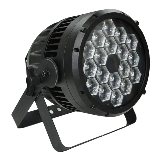
Page 6: Sl Punchlite 220 Overview
Yoke High Power LEDs DMX512 / RDM Input DMX512 / RDM Output AC Input AC Output Figure 1: SL PUNCHLITE 220 Common Components LCD Display / Menu System Edit a Preset Edit a Chase Home (menu settings) DMX512 Addressing Return to Main Screen... -
Page 7: Installation And Set Up
Connection from the AC output of another SL PUNCHLI TE 220. When using this method, it is very important not to connect any other type of equipment device. WARNING! Only connect other SL PUNCHLITE 220 to the AC Output (Thru) connector of a SL PUNCHLITE 220. Installation and Set Up... -
Page 8: Connecting The Sl Punchlite 220 To Ac Power
Connecting SL PUNCHLITE 220 to AC Power Table 2 describes how to connect power to your SL PUNCHLITE 220. Field wiring of th e SL PUNCHLITE 220 LED Luminaire is straight-forward. A total of 3 wires/conductors need to be brought to the unit. The following... -
Page 9: Connecting To The Dmx512 Network
"daisy-chain" fashion. A cable runs from the control console (or DMX512 control source) to the DMX connector on th e first SL PUNCHLITE 220. Anoth er cable runs from th e oth er DMX connector on th e first unit to a DMX connector on the next SL PUNCHLITE 220 (or DMX512 device to be controlled). -
Page 10: Mounting Luminaire
The SL PUNCHLITE 220 is provided with the ability to hang via truss hooks, clamps, etc. (sold separately). Simply attach hook, clamp, etc. to the SL PUNCHLITE 220 yoke in the provided M10 holes. It is recommended (and may be required by local and national safety codes) to use and install a safety cable (sold separately) as illustrated in Figure 6. -
Page 11: Operation And Programming
Installation & User’s Manual OPERATION AND PROGRAMMING LCD Display and Menu System SL PUNCHLITE 220 The SL PUNCHLITE 220’s LCD Display and Menu System provides local control for accessing the following fixture’s settings: Presets (Standard and User Defined) Color Filter... -
Page 12: Lcd Display And Menu System Operation
Installation & User’s Manual SL PUNCHLITE 220 2. LCD Display and Menu System Operation The LCD Display Menu system consists of several categories. Use the Menu Buttons to access and make changes to the menu items. When the desired menu item is reached, press the desired Menu Button to display the menu options and to navigate and configure the menu options as required. -
Page 13: Sl Punchlite 220 Menu Tree
0.2 S-60 Min Pixel 1-3_Intensity 0-100% Zoom Timing 0.2 S-60 Min Pixel 1-3_CCT 2700K-6500K Zoom 0-255 DMX Through On/Off Capture DMX Capture DMX Continued on next page Figure 9: SL PUNCHLITE 220 Menu Tree(Part 1) SL PUNCHLITE 220 Menu Tree... - Page 14 83 Celsius degree Warning High 86 Celsius degree Min_Value xx Celsius degree Max_Value xx Celsius degree Max Intensity 0-100% Other Information RDM UID 0X000000000000 Firmware Version Rev 0.0 Figure 10: SL PUNCHLITE 220 Menu Tree(Part 2) SL PUNCHLITE 220 Menu Tree...
-
Page 15: Quick Selection Buttons
SL PUNCHLITE 220 Installation & User’s Manual 4. Quick Selection Buttons When in Manual Mode, the SL PUNCHLITE 220's features can be accessed via the on-board LCD menu system or via three quick select buttons: Edit a Preset Button Edit a Chase Button... -
Page 16: Dimming Curve Selection
S_Curve Square Curve Linear Curve PL_Curve* DMX Value DMX Value *PL Curve follows the dimming curve of Philips Selecon PL series LED luminaires. S_Curve Square Curve DMX Value DMX Value Figure 11: SL PUNCHLITE 220 Dimmer Curves Dimming Curve Selection... -
Page 17: Master / Slave Operational Mode
6. Master / Slave Operational Mode The Master / Slave Operational Mode allows one SL PUNCHLITE 220 to act as the "Master" unit and all other connected units are controlled by this unit. When a unit is set to "Slave" mode, it will only listen to and follow any commands sent from a "Master"... -
Page 18: Dmx Control
SL PUNCHLITE 220 DMX Mapping Simple 8-Bit Mode Table 3 provides DMX channel mapping of all DMX512 control values when the SL PUNCHLITE 220 LED Luminaire is in simple 8-bit DMX512 mode (as set by the luminaire’s menu system). Table 3: SL PUNCHLITE 220 DMX Channel Mapping (Simple 8 - Bit Mode) -
Page 19: Simple 8-Bit Group Mode
Installation & User’s Manual 2. Simple 8-Bit Group Modes Table 4 provides DMX channel mapping of all DMX512 control values when the SL PUNCHLITE 220 LED Luminaire is operated in various Simple 8-bit DMX512 Group Control Modes. Table 4: SL PUNCHLITE 220 LED Luminaire DMX Channel Mapping (Simple 8-Bit Group Modes) -
Page 20: Rgbw 8-Bit Mode
SL PUNCHLITE 220 RGBW 8 - Bit Mode Table 5 provides DMX channel mapping of all DMX512 control values when the SL PUNCHLITE 220 LED Luminaire is in RGBW 8-bit DMX512 mode (as set by the luminaire’s menu system). Table 5: SL PUNCHLITE 220 DMX Channel Mapping (RGBW 8-Bit Mode) - Page 21 SL PUNCHLITE 220 SL PUNCHLITE 220 Installation & User’s Manual Installation & User’s Manual Table 5: SL PUNCHLITE 220 DMX Channel Mapping (RGBW 8-Bit Mode) Default - recom- Parameter Range DMX Range% mended console Description Channel default values CF_11_Moroccan Pink...
- Page 22 Installation & User’s Manual SL PUNCHLITE 220 Table 5: SL PUNCHLITE 220 DMX Channel Mapping (RGBW 8-Bit Mode) Default - recom- Parameter Range DMX Range% mended console Description Channel default values Chase 1 DMX 202 - 204 Chase 2 DMX 205 - 207...
- Page 23 SL PUNCHLITE 220 SL PUNCHLITE 220 Installation & User’s Manual Installation & User’s Manual Table 5: SL PUNCHLITE 220 DMX Channel Mapping (RGBW 8-Bit Mode) Default - recom- Parameter Range DMX Range% mended console Description Channel default values Zoom 0 - 100% Variable control of zoom from 8 –...
-
Page 24: Rgbw 8-Bit Group Mode
SL PUNCHLITE 220 4. RGBW 8-Bit Group Modes Table 6 provides DMX channel mapping of all DMX512 control values when the SL PUNCHLITE 220 LED Luminaire is operated in various RGBW 8-bit DMX512 Group Control Modes. Table 6: SL PUNCHLITE 220 LED Luminaire DMX Channel Mapping (RGBW 8-Bit Group Modes) -
Page 25: Rgbw 16-Bit Mode
Installation & User’s Manual RGBW 16 - Bit Mode Table 7 provides DMX channel mapping of all DMX512 control values when the SL PUNCHLITE 220 LED Luminaire is in RGBW 16-bit DMX512 mode (as set by the luminaire’s menu system). - Page 26 Installation & User’s Manual SL PUNCHLITE 220 Table 7: SL PUNCHLITE 220 DMX Channel Mapping (RGBW 16-Bit Mode) Default - recom- Parameter Range DMX Range% mended console Description Channel default values CF_11_Moroccan Pink DMX 91 - 92 CF_12_Pink DMX 93 - 94...
- Page 27 SL PUNCHLITE 220 SL PUNCHLITE 220 Installation & User’s Manual Installation & User’s Manual Table 7: SL PUNCHLITE 220 DMX Channel Mapping (RGBW 16-Bit Mode) Default - recom- Parameter Range DMX Range% mended console Description Channel default values Chase 1...
- Page 28 Installation & User’s Manual SL PUNCHLITE 220 Table 7: SL PUNCHLITE 220 DMX Channel Mapping (RGBW 16-Bit Mode) Default - recom- Parameter Range DMX Range% mended console Description Channel default values Variable control of zoom from 8 – 40 Zoom...
-
Page 29: Rgbw 16-Bit Group Mode
Installation & User’s Manual RGBW 16 - Bit Group Mode Table 8 provides DMX channel mapping of all DMX512 control values when the SL PUNCHLITE 220 LED Luminaire is operated in various RGBW 16-bit DMX512 Group Control Modes. Table 8: SL PUNCHLITE 220 LED Luminaire DMX Channel Mapping (RGBW 16-Bit Group Modes) -
Page 30: Hsic Mode
SL PUNCHLITE 220 HSIC Mode Table 9 provides DMX channel mapping of all DMX512 control values when the SL PUNCHLITE 220 LED Luminaire is in HSIC (Hue, Saturation, Intensity, and Color Correction) DMX512 mode (as set by the luminaire’s menu system). -
Page 31: Hsic Group Mode
Installation & User’s Manual HSIC Group Modes Table 10 provides DMX channel mapping of all DMX512 control values when the SL PUNCHLITE 220 LED Luminaire is operated in various HSIC DMX512 Group Control Modes. Table 10: SL PUNCHLITE 220 LED Luminaire DMX Channel Mapping (HSIC Group Modes) -
Page 32: Dmx Timing Channel Detail
DMX Timing Channel Detail Timing channel control improves the timed moves of certain groups of parameters. The SL PUNCHLITE 220 LED Luminaire provides timing channels in 16-bit mode (one for intensity time and one for color time) and one timing channel in 8-bit (color and intensity timing combined). - Page 33 SL PUNCHLITE 220 SL PUNCHLITE 220 Installation & User’s Manual Installation & User’s Manual Table 11: SL PUNCHLITE 220 Timing Channel Detail = Seconds % Value (unless noted) 10.2 10.4 10.6 10.8 11.2 11.4 11.6 11.8 DMX Timing Channel Detail...
- Page 34 Installation & User’s Manual SL PUNCHLITE 220 Table 11: SL PUNCHLITE 220 Timing Channel Detail = Seconds % Value (unless noted) 12.2 12.4 12.6 12.8 13.2 13.4 13.6 13.8 14.2 14.4 14.6 14.8 15.2 15.4 15.6 15.8 16.2 16.4 16.6 16.8...
- Page 35 SL PUNCHLITE 220 SL PUNCHLITE 220 Installation & User’s Manual Installation & User’s Manual Table 11: SL PUNCHLITE 220 Timing Channel Detail = Seconds % Value (unless noted) DMX Timing Channel Detail...
- Page 36 Installation & User’s Manual SL PUNCHLITE 220 Table 11: SL PUNCHLITE 220 Timing Channel Detail = Seconds % Value (unless noted) DMX Timing Channel Detail...
- Page 37 SL PUNCHLITE 220 SL PUNCHLITE 220 Installation & User’s Manual Installation & User’s Manual Table 11: SL PUNCHLITE 220 Timing Channel Detail = Seconds % Value (unless noted) 5 Minutes 15 Minutes 30 Minutes 60 Minutes 60mS 250* 80mS 251*...
-
Page 38: Rdm Parameter Ids
Installation & User’s Manual SL PUNCHLITE 220 1. SL PUNCHLITE 220 RDM Parameter IDs The following tables outline and describe all the RDM parameters Ids associated with SL PUNCHLITE 220 LED Luminaires. Table 12, “SL PUNCHLITE 220 RDM Product Parameters IDs”... - Page 39 SL PUNCHLITE 220 SL PUNCHLITE 220 Installation & User’s Manual Installation & User’s Manual Table 14: SL PUNCHLITE 220 RDM Parameters IDs RDM Parameter IDs Value Comment Implemented Allowed Allowed Category - Product Information DEVICE_INFO 0x0060 PRODUCT_DETAIL_ID_LIST 0x0070 DEVICE_MODEL_DESCRIPTION 0x0080...
- Page 40 PRESET_PLAYBACK 0x1031 Table 15: SL PUNCHLITE 220 RDM Parameter Status IDs Manufacturer Specific messages are in the range of 0x8000 - 0xFFDF. Each Manufacturer-specific Status ID shall have a unique meaning, which shall be consistent across all products having a given Manufacturer ID. See Table B-2, ANSI E1.20-2010...
-
Page 41: Cleaning And Care
WARNING! Under no circumstances should ammonia-based cleaners, acetone, or other harsh solvents be used on or near the SL PUNCHLITE 220. These types of cleaners or solvents can permanently damage the optics or housings of the fixture. -
Page 42: Technical Specifications
Installation & User’s Manual SL PUNCHLITE 220 TECHNICAL SPECIFICATIONS 1. OPERATIONAL SPECIFICATIONS 18 pcs RGBW LED Array Source: Beam Angle: 4-40 Degrees > 3800 lumens Light Output: Color Temerature: 2700 - 6500K (user adjustable) Input Voltage: 100V to 240V(+/- 10%, auto-ranging) 230 Watts(max). -
Page 43: Luminaire Dimensions
SL PUNCHLITE 220 SL PUNCHLITE 220 Installation & User’s Manual Installation & User’s Manual 2. Luminaire Dimensions LUMINAIRE DIMENSIONS... - Page 44 2014 Philips Group...
Need help?
Do you have a question about the SL PUNCHLITE 220 and is the answer not in the manual?
Questions and answers