Table of Contents
Advertisement
Quick Links
Download this manual
See also:
Instruction Manual
INSTALLATION GUIDE
VHF AIR BAND TRANSCEIVER
iA220
iA220E
SUPPLIED ACCESSORIES
z
The following accessories are supplied with the transceiver.
Carefully check the quantity of each part.
q
q Mounting bracket ................................................ 1
w D-Sub 25 pin connector
.................................... 1
e Connector pins (M39029/63-368) ........................... 25
r Screws Bind UNC (No. 4 × 3/8).............................. 2
t K-Lock Nut (No. 4) ............................................. 2
y BNC -LP
......................................................... 1
u Washer (Icom washer V) .................................... 1
i C-shaped ring ................................................... 1
o Antenna cable clip ............................................. 1
!0 Self crimping nut (No. 6)
.................................... 1
The following items are required for installation but are NOT
supplied with the transceiver.
• VHF antenna for the air communication band
• Various cables
• An antenna cable with a BNC connectors (50 Ω)
• Switches to be mounted on the aircraft yoke
• Headphones. (500 Ω)
• Low-impedance carbon or dynamic microphone
• Preamplifier for a dynamic microphone
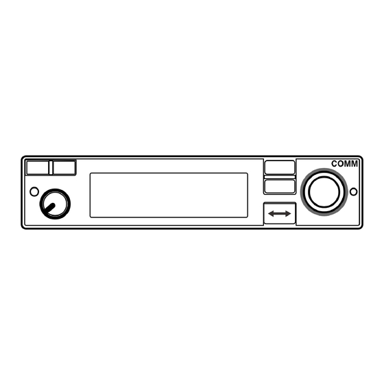
D COMM1 and COMM2 stickers
When two transceivers are installed, attach the supplied COMM1
and COMM2 stickers to distinguish one from the another.
COMM1
COMM2
or
sticker
COMM
Icom, Icom Inc. and Icom logo are registered trademarks of Icom Incorporated (Japan) in Japan, the United States, the United Kingdom, Germany, France, Spain,
Russia, Australia, New Zealand, and/or other countries.
CONNECTOR INFORMATION
n
D D-sub 25-pin
1 2 3 4 5 6 7 8
14 15
16 17 18 19 20
Pin
I/O
Description
1
In
Memory Channel Switch*
2
In
Transmit/receive Interlock
3
In
Frequency Exchange Switch*
4
In
DC power + (13.8/27.5 V)
5
In
DC power + (13.8/27.5 V)
6
–
RS-232C Serial data (GND)
7
Out RS-232C Serial data (TXD)
8
In
RS-232C Serial data (RXD)
Microphone (GND)
9
–
Microphone 1 (600 Ω)
10
In
11
In
Microphone 2 (600 Ω)
12
In
Auxiliary audio 1
13
In
Auxiliary audio 2
D Card edge connector (For optional MBA-3)
A B C D E F H J K L M N P R S
1 2 3 4 5 6 7 8 9 101112131415
Pin
I/O
Description
A
I
External Dimmer Control
B
–
(reserved)
C
In
Auxiliary audio 2
D
In
Auxiliary audio 1
E
Out External speaker (4 Ω/5 W)
F
–
Aircraft ground
Out Headphones audio (500 Ω/60 mW)
H
J
In
Microphone 1 (600 Ω)
K
In
Microphone 2 (600 Ω)
L
In
Memory channel switch*
M
–
(reserved)
N
I
Transmit/receive interlock
P
–
(reserved)
R
In
DC power + (13.8/27.5 V)
S
–
Aircraft ground
Thank you for choosing the IC-A220/IC-A220E
with Icom's state of the art
air band transceiver
technology.
Carefully read this installation guide and the trans-
ceiver's instruction manual before installing and op-
erating your transceiver.
w
e
r
t
y
u
i
o
!0
!1
!2
!3
!4
!5
!6
!7
!8
!1 Screw (No. 6 × 1/2) ............................................. 1
!2 Nut (No. 6) ...................................................... 1
!3 Crimp nuts (No. 6) ............................................. 6
!4 Speed nut UNC (No. 6) ....................................... 4
!5 Screws (No. 6 × 1/2) .......................................... 6
!6 COMM1 sticker ................................................ 1
!7 COMM2 sticker ................................................ 1
!8 Voltage sticker (For only IC-A220E) ........................ 1
D Voltage sticker
(For only IC-A220E)
When you install the transceiver in the optional MB-53,
attach the supplied voltage sticker on the MB-53.
Voltage sticker
MB-53
9 10 11 12 13
Rear view
21 22 23 24 25
Pin
I/O
Description
14
–
Aircraft ground
15
–
Aircraft ground
16
In
PTT*
17
In
Intercom switch*
18
Out External speaker (4 Ω/5 W)
External speaker (GND)
19
–
20
Out Headphones audio (500 Ω/60 mW)
21
In
External Dimmer control
Headphones audio (GND)
22
–
23
In
Auxiliary audio 3
24
–
(reserved)
25
–
(reserved)
*Ground to activate.
Polarizing key (user supplied)
Rear view
Pin
I/O
Description
1
Out RS-232C Serial data (TXD)
2
In
RS-232C Serial data (RXD)
3
In
Auxiliary audio 3
4
–
Auxiliary audio 1/2/3 (GND)
5
–
External speaker (GND)
6
–
Aircraft ground
7
–
Headphones audio (GND)
8
–
Microphone (GND)
9
In
PTT*
10
In
Intercom switch*
11
–
(reserved)
12
In
Frequency exchange switch*
13
–
(reserved)
14
In
DC power + (13.8/27.5 V)
15
–
Aircraft ground
*Ground to activate.
IMPORTANT
x
vhf
READ THIS INSTALLATION GUIDE CAREFULLY before
install the transceiver. This installation guide contains impor-
tant safety instructions.
NEVER
install the transceiver where normal navigation of
the aircraft may be hindered.
NEVER
install an antenna near any aircraft projection, en-
gine, or propeller.
Install a circuit breaker between the aircraft battery and the
transceiver.
INSTALLATION PROCEDURES
c
q Check the quantity of parts.
Refer to z SUPPLIED ACCESSORIES.
w Prepare miscellaneous items required for installation.
Refer to miscellaneous items in z SUPPLIED ACCES-
SORIES.
e Prepare the required wiring.
Refer to n CONNECTOR INFORMATION and m CON-
NECTING THE CABLES FOR D-SUB 25 PIN.
• If you want to use the MBA-3 connector, refer to
ING THE MBA-3 and , CONNECTING THE CABLES FOR
CARD EDGE CONNECTOR.
r Assemble supplied mounting bracket and other parts.
Refer to . MOUNTING BRACKET ASSEMBLY.
t Cut the mounting hole.
Refer to ⁄ 0 MARKING A MOUNTING HOLE.
y Mount the transceiver into the mounting bracket.
Refer to ⁄1 MOUNTING TO THE BRACKET.
u Check the transceiver operation.
Refer to ⁄ 2 OPERATION CHECK.
USING THE MBA-3
b
When installing the transceiver with card edge connector, use
the optional MBA-3 as described below.
D Attachment
q
Unscrew the 10 bottom screws, then remove the bottom
cover from the transceiver.
Unscrew the four rear plate screws.
w
Disconnect the I/O cable connectors J3, J4, and coaxial
e
J6 , and then remove the rear plate from the transceiver.
Transceiver
J3
CONNECTING THE CABLES FOR D-SUB 25 PIN
m
D Power cable wiring
Use two pairs of #20 AWG wire for the power and power
grounding connections.
Rear view
1
4
5
14
15
_
Power ground
Circuit breaker
(10 A)
• Circuit breaker
To prevent physical damage, a 10 A circuit breaker MUST be
installed in the DC power line in the aircraft. Install the circuit
breaker in the aircraft breaker panel or instrument panel to
ensure easy access during flight.
• Power Ground
Connect the transceiver power ground to the aircraft ground.
D Yoke-mounted memory and frequency exchange
switches
For the yoke-mounted memory and frequency exchange
switches, use a two-position spring loaded rocker switch or
two separate momentary push switches.
Rear view
1
3
14
Frequency exchange switch
Memory switch
OR
1
3
14
Frequency exchange switch
Memory switch
D Transmit/receive interlock connections
When two transceivers are installed, connect pin 2 to the
other transceiver
PTT line, and connect pin 16 to the other
's
transceiver
's
interlock line to prevent both transceivers from
simultaneously transmitting.
However, when two transceivers are installed through a dual
audio panel, the connections are not necessary.
Check operation after installation.
Install the transceiver according to the procedures of this in-
stallation guide.
The antenna should be spaced at least 40 cm (1.3 feet) from
any position occupied by any person on board the aircraft or
the vehicle.
PRECAUTIONS
v
NEVER bend the cables sharply or place the cables too near
the aircraft control cables.
DO NOT place the transceiver where hot or cold air blows di-
rectly on it.
AVOID placing the transceiver in areas with temperatures be-
low –20˚C or above +55˚C (–4˚F to +131˚F).
NEVER connect the transceiver to a power source using re-
verse polarity. Reverse polarity will damage the transceiver.
To prevent voltage drops, solder or crimp the cable lug when
b US-
connecting the DC power cable to the power supply.
Use a 50 Ω, vertically polarized, VHF air band antenna.
VSWR should be less than 2.5:1.
Mount the antenna on a flat metal surface or install a ground
2
plane of at least 120 cm
(18 in
Connect the I/O cable connectors and coaxial onto the
r
MBA-3 as illustrated below.
J6
J4
Rear plate
Attach the MBA-3 to the transceiver with the five rear plate
t
screws.
y
Replace the removed bottom cover and 10 screws.
D Audio line connections
Use #20 ~ #24 AWG wires for connections.
Rear view
• Two headsets with intercom
13
9 10 11
12
1
25
+
13.8 V DC
14
16 17
20
23
19
or 27.5 V DC
18
22
External
speaker
Headphone jack 1
Headphone jack 2
• One headset
9 10
1
12
14
16
22 23
19
18
Headphone jack
20
13
External
speaker
D GPS receiver connection
Connect the GPS receiver's input terminal to the pin 7, and
25
output terminal to pin 8.
Rear view
GPS receiver's input
13
GPS receiver's output
1
7
8
25
14
2
).
Transceiver
MBA-3
PTT switch
Intercom switch
13
Auxiliary audio 1
Audio
Auxiliary audio 2
control
panel
Auxiliary audio 3
25
Microphone
jack 1
Microphone
jack 2
PTT switch
Microphone
jack
13
Auxiliary audio 1
Audio
Auxiliary audio 2
control
Auxiliary audio 3
panel
25
GPS
receiver
13
25
Advertisement
Table of Contents

Subscribe to Our Youtube Channel
Related Manuals for Icom IC-A220E


Summary of Contents for Icom IC-A220E
-
Page 1: Supplied Accessories
Replace the removed bottom cover and 10 screws. Icom, Icom Inc. and Icom logo are registered trademarks of Icom Incorporated (Japan) in Japan, the United States, the United Kingdom, Germany, France, Spain, Russia, Australia, New Zealand, and/or other countries. - Page 2 - NO interference caused to other equipment. - NO noise or interference from other equipment. 160 mm (6 ″) ⁄ A-7210D-2EX-a 1-1-32 Kamiminami, Hirano-ku, Osaka 547-0003, Japan Printed in Japan Printed on recycled paper with soy ink. © 2015 Icom Inc.
Need help?
Do you have a question about the IC-A220E and is the answer not in the manual?
Questions and answers