Table of Contents
Advertisement
Quick Links
Advertisement
Chapters
Table of Contents

Related Manuals for Edimax HP-5102Wn


Summary of Contents for Edimax HP-5102Wn
- Page 1 HP-5102Wn User Manual 12-2014 / v1.0...
- Page 2 COPYRIGHT Copyright Edimax Technology Co., Ltd. all rights reserved. No part of this publication may be reproduced, transmitted, transcribed, stored in a retrieval system, or translated into any language or computer language, in any form or by any means, electronic, mechanical, magnetic, optical, chemical, manual or otherwise, without the prior written permission from Edimax Technology Co., Ltd.
-
Page 3: Table Of Contents
CONTENTS PRODUCT INFORMATION ......................1 I-1. Package Contents ........................1 I-2. Hardware ........................... 2 I-3. LED Status ..........................3 I-4. Resetting the Powerline Adapter ....................4 I-5. Safety Information ........................5 POWERLINE NETWORK ........................ 6 II-1. Installation ..........................6 II-2. Leaving a Powerline Network .................... -
Page 4: Product Information
I. PRODUCT INFORMATION I-1. Package Contents Before you start using this product, please check if there is anything missing in the package, and contact your dealer to claim the missing items(s): HP-5102Wn Ethernet Cable CD-ROM Quick Installation Guide... -
Page 5: Hardware
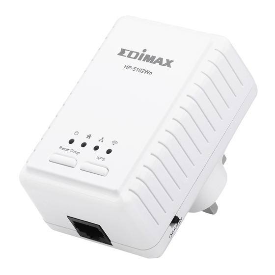
I-2. Hardware LEDs See I-3. LED Status below. Press for 10+ seconds to reset the HP-5102Wn Powerline function (PLC utility settings) to factory defaults, and less Reset/Group 3 seconds to connect with another Powerline adapter. Button Press for 5 - 8 seconds to leave an encrypted powerline network group. -
Page 6: Led Status
I-3. LED Status Color LED Status Description HP-5102Wn is on. Power Establishing Powerline Green Flashing connection. HP-5102Wn is off. Powerline connection detected. Powerline traffic: excellent Flashing connection. Green No Powerline connection detected. Powerline traffic: good Orange Flashing connection. Powerline connection: bad Flashing connection. -
Page 7: Resetting The Powerline Adapter
I-4. Resetting the Powerline Adapter If you experience a problem with your HP-5102Wn you can reset the device back to its factory default settings. To reset Powerline settings, press and hold the Reset/Group button for at least 10 seconds. The power LED ( ) will display on when the HP-5102Wn is ready (see LED Status). -
Page 8: Safety Information
I-5. Safety Information In order to ensure the safe operation of the device and its users, please read and act in accordance with the following safety instructions. 1. The powerline adapter is designed for indoor use only; do not place the powerline adapter outdoors. -
Page 9: Powerline Network
The power and LAN LEDs should display on. 2. Plug the HP-5102Wn into a power socket, and confirm the power LED is on. 3. The PLC LED on both Powerline adapters should indicate that a Powerline connection is established. - Page 10 The adapters will automatically group together and generate an encrypted network. 5. To connect to your HP-5102Wn’s Wi-Fi, use a Wi-Fi device (e.g. computer, tablet, smartphone) to search for a Wi-Fi network with the SSID “EdimaxPLC_***” and connect to it. The password is displayed on the product label.
-
Page 11: Ii-2. Leaving A Powerline Network
6. You can also use an Ethernet cable to connect a computer or other device to the HP-5102Wn using the Ethernet port on the underside of the product. II-2. Leaving a Powerline Network Press the “Reset/Group” button on the powerline adapter for 5–8 seconds to leave a Powerline network that the HP-5102Wn is connected to. -
Page 12: Ii-3. Wps Setup
HP-5102Wn’s Wi-Fi after you have established a Powerline connection. Press the WPS button on the HP-5102Wn for less than 2 seconds to activate WPS. The HP-5102Wn’s Wi-Fi LED will display on to indicate that WPS is active. -
Page 13: Wi-Fi Configuration
III. WI-FI CONFIGURATION To make configurations to your HP-5102Wn (e.g. change the SSID & password) you can use the product’s web-based control panel. To access the control panel, follow the instructions below: Note: By default, the HP-5102Wn is set to use a dynamic IP address from your router. - Page 14 Go to 192.168.2.2 in a web browser and you will arrive at the login screen, as shown below. The default username is admin and the default password is 1234. Note: If you cannot access the control panel, please unplug your HP-5102Wn and plug it back in, and try again.
-
Page 15: Iii-1. Setup Wizard
III-1. Setup Wizard Click “Start Setup Wizard” to set the SSID and password of the powerline adapter. Name (SSID) Enter the network name(SSID) name for the Wi-Fi network. The SSID can consist of any combination of up to 32 alphanumeric characters. -
Page 16: Iii-2. Device Configuration
III-2. Device Configuration Select “DHCP” for your powerline adapter to be assigned a dynamic IP address from your router’s DHCP server, or select “Fixed IP” to manually specify a static/fixed IP address for your powerline adapter. When using “DHCP” check your router’s settings to find your powerline adapter’s IP address. -
Page 17: Iii-3. Wlan Configuration
III-3. WLAN Configuration When data is The powerline adapter provides three security/encryption options. encrypted, information transmitted wirelessly cannot be read by anyone who does not know the correct encryption key. By default, WPA encryption is enabled. It’s essential to configure wireless security in order to prevent unauthorised access to your network. - Page 18 Name (SSID) Enter the network name (SSID) for the Wi-Fi network. The SSID can consist of any combination of up to 32 alphanumeric characters. Channel Select a radio channel for your Wi-Fi or use the auto setting. Selecting a less-crowded channel can improve performance due to less interference from other Wi-Fi devices.
-
Page 19: Iii-4. Status Overview
III-4. Status Overview Displays the current firmware version and the MAC address of any wireless clients which are connected to the powerline adapter. -
Page 20: Iii-5. Management
III-5. Management The sub-menu provides access to various management settings:... -
Page 21: Iii-5-1
III-5-1. Account Account settings are the username and password used to log in to the control panel. The default values are username: admin password: 1234. It is recommended to change account settings according to your preference. -
Page 22: Iii-5-2
III-5-2. DHCP Server Enable or disable the powerline adapters DHCP server. The DHCP server will automatically assign an IP address to network devices connected to the powerline adapter. You can specify a range of IP address to assign. Do not enable DHCP server is your router has also enabled DHCP server. -
Page 23: Iii-5-3
III-5-3. Factory Restore You can restore the powerline adapter back its factory default state. This resets all settings including SSID, password and IP settings. -
Page 24: Iii-5-4
III-5-4. WLAN Radio Configuration You can configure the powerline adapter’s Wi-Fi radio. Name (SSID) Enter the network name (SSID) for the Wi-Fi network. The SSID can consist of any combination of up to 32 alphanumeric characters. Channel Select a radio channel for your Wi-Fi or use the auto setting. - Page 25 Channel Width Select wireless channel width (bandwidth used by wireless signals from the device) – the recommended value is HT20/40.
-
Page 26: Powerline Utility Software
IV. POWERLINE UTILITY SOFTWARE The included CD-ROM contains Powerline utility software which provides powerline diagnostic information and management for advanced users. Before installating the utility software, please uninstall any existing Powerline utility software you may already have. To install the utility software, insert the CD into your CD-ROM drive and the setup wizard should begin automatically. -
Page 27: Iv-1. Using The Utility
IV-1. Using the Utility The following pages describe the functions of each tab within the Powerline utility software. IV-1-1. Main The “Main” tab provides a list of Powerline adapters connected to the network. Use the drop down menu to select a network card if you have more than one installed on your computer. - Page 28 Name This column shows the default device name, for example: “Device 2”, “Device 3”. If you want to change the name, please click “Set Name” button to edit the name. MAC Address The adapter’s MAC address will be shown here. Password This column by default is blank.
-
Page 29: Iv-1-2. Diagnostics
Security Network Name Powerline adapters often ship with the same default network name “HomePlugAV”. Powerline adapters with the same network name can be connected together. If you want to create another network, please enter the new network name and select “Set all remote devices whose password has been entered”... -
Page 30: Iv-1-3. About
IV-1-3. About The “About” tab displays basic information about the software. -
Page 31: Appendix
V. APPENDIX How to Modify the IP Address of Your PC or Mac Please follow the instructions appropriate for your operating system. In the following examples we use the IP address 192.168.2.10. V-1. Windows XP 1. Click the “Start” button (it should be located in the lower-left corner of your computer), then click “Control Panel”. -
Page 32: V-2. Windows Vista
V-2. Windows Vista 1. Click the “Start” button (it should be located in the lower-left corner of your computer), then click “Control Panel”. Click “View Network Status and Tasks”, then click “Manage Network Connections”. Right-click “Local Area Network”, then select “Properties”. The “Local Area Connection Properties” window will then appear, select “Internet Protocol Version 4 (TCP / IPv4)”, and then click “Properties”. -
Page 33: Windows 7
V-3. Windows 7 1. Click the “Start” button (it should be located in the lower-left corner of your computer), then click “Control Panel”. 2. Under “Network and Internet” click “View network status and tasks”. - Page 34 3. Click “Local Area Connection”. 4. Click “Properties”.
-
Page 35: V-4. Windows 8/8.1
5. Select “Internet Protocol Version 4 (TCP/IPv6) and then click “Properties”. 6. Select “Use the following IP address”, then input the following values: IP address: 192.168.2.10 Subnet Mask: 255.255.255.0 Click ‘OK’ when finished. V-4. Windows 8/8.1 1. From the Windows 8 Start screen, you need to switch to desktop mode. Move your curser to the bottom left of the screen and click. - Page 36 2. In desktop mode, click the File Explorer icon in the bottom left of the screen, as shown below.
- Page 37 3. Right click “Network” and then select “Properties”. 4. In the window that opens, select “Change adapter settings” from the left side.
- Page 38 5. Choose your connection and right click, then select “Properties”. 6. Select “Internet Protocol Version 4 (TCP/IPv4) and then click “Properties”.
-
Page 39: V-5. Mac Os
7. Select “Use the following IP address”, then input the following values: IP address: 192.168.2.10 Subnet Mask: 255.255.255.0 Click ‘OK’ when finished. V-5. Mac OS 1. Have your Macintosh computer operate as usual, and click on “System Preferences” 2. In System Preferences, click on “Network”. 3. - Page 40 4. Click on “Ethernet” in the left panel and then click the drop down arrow for the menu labeled “Configure IPv4” in the right panel. From the drop down menu, select “Manually”. 5. In the panel on the right side, enter IP address 192.168.2.10 and subnet mask 255.255.255.0.
-
Page 41: V-6. Glossary
V-6. Glossary Default Gateway (Wireless bridge): Every non-access point IP device needs to configure a default gateway’s IP address. When the device sends out an IP packet, if the destination is not on the same network, the device has to send the packet to its default gateway, which will then send it out towards the destination. - Page 42 11111111.11111111.11111111.00000000. Therefore sometimes a network mask can also be described simply as “x” number of leading 1’s. When both are represented side by side in their binary forms, all bits in the IP address that correspond to 1’s in the network mask become part of the IP network address, and the remaining bits correspond to the host ID.
- Page 43 Telnet SMTP POP3 H.323 1720 SNMP SNMP Trap HTTP PPTP 1723 PC Anywhere TCP 5631 PC Anywhere UDP 5632 Access point: A access point is an intelligent network device that forwards packets between different networks based on network layer address information such as IP addresses.
-
Page 44: Federal Communication Commission Interference Statement
Federal Communication Commission Interference Statement This equipment has been tested and found to comply with the limits for a Class B digital device, pursuant to Part 15 of FCC Rules. These limits are designed to provide reasonable protection against harmful interference in a residential installation. This equipment generates, uses, and can radiate radio frequency energy and, if not installed and used in accordance with the instructions, may cause harmful interference to radio communications. - Page 45 EU Declaration of Conformity English: This equipment is in compliance with the essential requirements and other relevant provisions of Directive 1999/5/EC, 2009/125/EC, 2006/95/EC, 2011/65/EC. French: Cet équipement est conforme aux exigences essentielles et autres dispositions de la directive 1999/5/CE, 2009/125/CE, 2006/95/CE, 2011/65/CE. Toto zařízení...
-
Page 46: Declaration Of Conformity
Declaration of Conformity We, Edimax Technology Co., Ltd., declare under our sole responsibility, that the equipment described below complies with the requirements of the European R&TTE directive. Equipment: AV500 PowerLine Wi-Fi Extender Model No.: HP-5102Wn The following European standards for essential requirements have been followed:... - Page 48 HP-5102AC User Manual 02-2013 / v1.0...
- Page 49 COPYRIGHT Copyright Edimax Technology Co., Ltd. all rights reserved. No part of this publication may be reproduced, transmitted, transcribed, stored in a retrieval system, or translated into any language or computer language, in any form or by any means, electronic, mechanical, magnetic, optical, chemical, manual or otherwise, without the prior written permission from Edimax Technology Co.,...
- Page 50 Contents Chapter 1: Introduction ............................. 3 1.1 Product Features ..........................3 1.2 Application ............................3 1.3 Compatibility ............................4 1.4 System Requirements .......................... 4 Chapter 2: About the Product ..........................5 2.1 LED Definitions ............................. 5 2.2 Interface ............................... 6 2.3 Fast Ethernet Port ..........................
-
Page 51: Chapter 1: Introduction
Chapter 1: Introduction 1.1 Product Features Easy plug-n-play setup and 128-bit AES security Max. powerline speed up to 500Mbps Backward compatible with 200Mbps powerline adapters Features energy saving mode to reduce power consumption Utilizes existing electrical wires to transmit network data ... -
Page 52: Compatibility
1.3 Compatibility 500Mbps powerline devices (HomePlug AV standard) are incompatible and cannot be used with 14Mbps and 85Mbps powerline devices (HomePlug 1.0 and 1.1 standards). 1.4 System Requirements Operating System Utility supports Windows XP/Vista/7/8 Intel Pentium III 1.0GHz (or above) 256MB (or above) Free Disk Space 100MB (or above) -
Page 53: Chapter 2: About The Product
Chapter 2: About the Product 2.1 LED Definitions Status Description Green LAN port connected Blinking LAN activity (transferring data) LAN port not connected The green indicator turns on and the yellow indicator blinks slowly when the device is detecting a powerline link. -
Page 54: Interface
2.2 Interface Interface Description Integrated The integrated electrical socket enables additional terminal Power Socket devices or multiple socket to be connected to the adapter, just as a normal wall socket would. Ethernet Port This is a Fast Ethernet port for connecting to a computer or other devices with a network port. -
Page 55: Chapter 3:Utility Software Installation
Chapter 3:Utility Software Installation 3.1 Win 8 Step 1 Before installing the utility software, make sure that no other powerline utility is installed on your computer. If any other utility software is installed, uninstall it and reboot the computer. Step 2 Insert the CD into your CD-ROM drive. When the following EZmax Wizard appears, select your model. - Page 56 Step 4 Click right button on WinPCap4.1.2 then click “Properties”. Step 5 Click Compatibility tab and check “Run this program in compatibility mode for:", then select Windows 7, then click “Apply”.
- Page 57 Step 6 Then click “WinPcap_4_1_2”. The wizard will guide you through the setup process. Step 7 When the following WinPcap Compatibility Assistant appears, select Run the program without getting help.
- Page 59 Step 8 After the installation is complete, click “Finish”.
- Page 60 Step 9 Click the “Edimax PowerLine Utility”, the “PLC 500Mbps Utility” appears, click “Next” to continue. Step 10 Select where you want to install the utility software, and then click “Next”.
- Page 61 Step 11 After the installation is complete, click “Close”.
- Page 62 Step 12 An icon will appear on your desktop. Click the icon to open the utility software. Note: You can manage all the connected powerline adapters with the utility software. However, installing the utility software is optional.
-
Page 63: Win Xp/Vista / 7
3.2 Win XP/Vista / 7 Step 1 Before installing the utility software, make sure that no other powerline utility is installed on your computer. If any other utility software is installed, uninstall it and reboot the computer. Step 2 Insert the CD into your CD-ROM drive. When the following EZmax Wizard appears, select your model. - Page 64 Step 4 If you have not installed WinPcap version 4.1.2 (or higher) on your computer before. The wizard will guide you through the setup process.
- Page 66 Step 5 When the “Edimax PowerLine Utility” setup wizard appears, click “Next” to continue. Step 6 In the “License Agreement” screen, please select “I Agree” and then click “Next” to continue.
- Page 67 Step 7 Select where you want to install the utility software, and then click “Next”. Step 8 If you confirm to install the utility, click “Next”.
- Page 68 Step 9 After the installation is complete, click “Close”. Step 10 An icon will appear on your desktop. Click the icon to open the utility software. Note: You can manage all the connected powerline adapters with the utility software. However, installing the utility software is optional.
-
Page 69: Chapter 4: Using The Utility Software
Chapter 4: Using the Utility Software 4.1 Main Tab The “Main” tab provides a list of powerline adapters connected to the network. The upper panel displays local powerline adapters. The lower panel displays remote powerline adapters in the network. Set Name Select a device and click “Set Name”... -
Page 70: Diagnostics Tab
4.2 Diagnostics Tab The “Diagnostics” tab displays the system information and history of all remote devices. The upper panel displays technical data concerning the software and hardware on the host computer and the lower panel displays the history of all remote devices. -
Page 71: About Tab
4.3 About Tab The “About” tab contains some basic information about the software. You can also enable or disable the autoscan function under “Preferences”. -
Page 72: Chapter 5: Group Button
Chapter 5: Group Button This section demonstrates how to add or remove devices from a HomePlug AV network with the “Group” button. 5.1 Forming a HomePlug AV Logical Network When two devices with different group keys are connected to the same powerline and you want them to form a logical network, follow the following procedures: Step 1 Press and hold the “Group”... -
Page 73: Joining A Network
5.2 Joining a Network If you want to add a new powerline device to an existing network, follow the following procedures: Step 1 Press the “Group” button on an adapter in the existing network (adapter A or B) for less than 3 seconds. The Power LED will start to blink. Step 2 Within 120 seconds after the Power LED starts blinking on adapter A or B, press the “Group”... -
Page 74: Leaving A Network & Joining Another Network
5.3 Leaving a Network & Joining another Network If you want to remove a powerline device from an existing network and add it to another network, follow the following procedures: Step 1 Press the “Group” button on the adapter to be removed (adapter B) for at least 10 seconds. -
Page 75: Chapter 6: Troubleshooting
Chapter 6: Troubleshooting If your powerline adapters have difficulty communicating with each other, try the following procedures: Try power cycling the unit by unplugging it from the electric outlet for 10 seconds and plugging it in again. Use a pin to hold the reset button down for 2 seconds on each unit you are trying to connect. - Page 76 Federal Communication Commission Interference Statement This equipment has been tested and found to comply with the limits for a Class B digital device, pursuant to Part 15 of FCC Rules. These limits are designed to provide reasonable protection against harmful interference in a residential installation.
- Page 77 EU Declaration of Conformity English: This equipment is in compliance with the essential requirements and other relevant provisions of Directive 2004/108/EC, 2009/125/EC. Français: Cet équipement est conforme aux exigences essentielles et autres dispositions de la directive 2004/108/EC, 2009/125/EC Čeština: Toto zařízení je v souladu se základními požadavky a ostatními příslušnými ustanoveními směrnic 2004/108/EC, 2009/125/EC.
Need help?
Do you have a question about the HP-5102Wn and is the answer not in the manual?
Questions and answers