Table of Contents
Advertisement
Quick Links
Advertisement
Table of Contents

Related Manuals for Asante IntraCore 8000


Summary of Contents for Asante IntraCore 8000
-
Page 1: Ethernet Switch
IntraCore 8000 Ethernet Switch User’s Manual August 2000 Part Number 06-00566-00... -
Page 2: Copyright Notice
Copyright Notice All rights reserved. No part of this manual, or any associated artwork, software, product, design or design concept, may be copied, reproduced or stored, in whole or in part, in any form or by any means mechanical, electronic, optical, photocopying, recording or any other wise, including translation to another language or format, without the express written consent of Asanté... -
Page 3: Table Of Contents
The Core Switching Engine ... 1-1 Infrastructure Connectivity ...1-2 Network Management, Security, Performance, and Control ...1-2 The IntraCore Product Family ... 1-3 The IntraCore 8000 ... 1-5 Expansion Modules ...1-5 8-port 10/100 Switch Module ... 1-5 Gigabit Ethernet Switch Module ... 1-6 Features ... - Page 4 Management Options ... 2-13 Out-of-Band Management ... 2-13 In-Band Management ... 2-14 Configuration ... 3-1 Local Management Interface ... 3-2 Logging In ... 3-2 Main Menu ... 3-3 Viewing General Information ... 3-4 Configuration Menu ... 3-6 System Administration Configuration ... 3-8 Current Settings ...
- Page 5 Image Downloading Through TFTP ... 3-39 Serial Downloading Configuration ... 3-42 System Reset Configuration ...3-45 Current Options ... 3-46 Resetting the IntraCore 8000 ... 3-46 Scheduling a System Reset ... 3-47 Viewing the System Log ... 3-47 Clearing the System Log ... 3-48 User Interface Configuration ...3-49...
- Page 6 Inserting/Modifying a Port Trusted MAC Address ... 4-17 Resetting Security to Defaults ... 4-17 VLAN Management ... 4-18 VLAN Specifications for the IntraCore 8000 ... 4-18 Other VLAN Features in IntraCore 8000 ... 4-19 Overview of VLANs ... 4-19 VLAN Groups ... 4-21 Independent vs.
- Page 7 VLAN Button ... 5-14 Port Configuration ...5-14 VLAN Configuration ... 5-15 Duplicate IP Button ... 5-19 Technical Support ... A-1 Contacting Technical Support ... A-1 MIB Statistics ... B-1 MIB Object Definitions for Counters ... B-1 Readable Frames ... B-1 Readable Octets ...
- Page 8 Page vi...
-
Page 9: Introduction
This chapter introduces the IntraCore architecture, then gives a description of the chassis and the various modules that can be installed in the IntraCore 8000. There are also tables of the key features, default settings, and specifications of the IntraCore 8000, and explanations of the different LED indicators used by the various modules. -
Page 10: Infrastructure Connectivity
Introduction Infrastructure Connectivity The second key element of the architecture is Infrastructure Connectivity. IntraCore specifies standards based, high performance, cost effective technologies for connectivity among devices in the network. In the LAN – At the network edge, Layer 2 switched 10/100/1000 Ethernet meets the requirements for high-speed connectivity of desktop computers and scalable, cost effective data transmission for trunks to the network core. -
Page 11: The Intracore Product Family
Feature Web Browser Management SNMP, RMON Standard MIsS 802.1P Priority 802.1Q VLAN Tagging 802.1D – Spanning Tree IGMP V1, V2 Snooping RSVP Snooping GARP Multicast Registration Duplicate IP addr. detection Station movement notification IP to MAC address binding Controlled management access GVRP (Group VLAN Regis- tration Protocol) Advanced Port Configuration:... -
Page 12: Edge Switches
The initial product introduced in the Edge Switch category is the IntraCore 8000. The IntraCore 8000 is a stackable, high performance solution for enterprise edge applications. Each stack supports up to 192 10/100Mbps switched Ethernet connections for cost-effective high-density connectivity in wiring closets. -
Page 13: The Intracore 8000
The IntraCore 8000 The IntraCore 8000 The IntraCore 8000 is a stackable, high performance solution for enterprise edge applications. Each stack supports up to 192 10/100Mbps switched Ethernet connections for cost-effective high-density connectivity in wiring closets. The system can operate as a stand-alone network or be used in combination with an IntraCore 8000 in the backbone. -
Page 14: Gigabit Ethernet Switch Module
Introduction Gigabit Ethernet Switch Module This module provides a slot for a switched Gigabit Ethernet port. Each module occupies a single slot and has a GBIC port that accepts Asanté or third party GBIC interfaces. The following subsections describe the possible GBIC interfaces. -
Page 15: Features
Features The following table lists the major features of the IntraCore 8000 switch. Feature Media Flexibility High Density ASIC-Based Architec- ture High Performance 16Gbps Backplane Multiple Priority Queues Stackable Form Factor with modular expan- sion options Configuration Flexibil- ity and Growth... - Page 16 MAC address is allowed to connect to that specific port. Built-in Web-based interface is provided for chassis manage- ment, module management, port-level control, and monitoring. The IntraCore 8000 can also be managed via Telnet, Console, or third party SNMP console. Supports up to 64 port-based VLANs (IEEE 802.1Q compliant) for security, logical network design, and the control of broad- cast traffic.
-
Page 17: Defaults And Specifications
Defaults and Specifications The IntraCore 8000 is shipped with the following factory default settings and specifications: Configuration Backplane Speed Switching Method Forwarding Rates: (64 byte packets) Buffer Size MAC Address Table Full-Duplex VLAN Spanning Tree Protocol Flood Rate Limiting Priority... -
Page 18: Leds
Page 1-10 Color and Meaning Green - Power is on when lit Specifies IntraCore 8000 Unit – #1 is bottom unit Specifies IntraCore 8000 unit with management CPU Indicates whether or not current unit has the Matrix module for the other units in the stack... -
Page 19: Installation And Setup
Installation Guidelines The following guidelines will help you prepare to install your IntraCore 8000 in such a way that it has the proper power supply and environment. Power Requirements The source electrical outlet should be installed near the IntraCore 8000 and easily accessible. -
Page 20: Installation Overview
Installation and Setup Installation Overview The table below describes the steps needed to install the IntraCore 8000. The steps that are optional are labeled “optional” and the steps that are required are labeled “required.” The sections that follow explain each step in detail. -
Page 21: Chassis Installation/Placement
Depth: 19.25 inches (48.9 cm) to 32 inches (81.3 cm). Stability Rack must be bolted to the floor. Mount heavier units at the bottom of the rack. If the IntraCore 8000 is the only unit, mount it the bottom of the rack.. Ventilation Ensure that the rack is installed in a room where the temperature remains below 40°... -
Page 22: Free-Standing/Desktop Placement
Proceed to the section, “Installing Port Expansion Mod- ules.” Free-Standing/Desktop Placement The IntraCore 8000 has four rubber feet on the bottom of the case that allow for free-standing placement of the unit. For free-standing/desktop placement: Attach the four rubber pads (supplied) to the bottom of each corner of the IntraCore 8000 chassis. -
Page 23: Stacking Switches
Stacking Switches Up to four IntraCore 8000 switches may be connected within a stack. In each of the different configurations, bandwidth increases to meet the growth of traffic. Two Stack Configuration If you wish to add a single switch to create a stack of two, take the following steps. - Page 24 Stack Connector modules on the other switches. Use the 50-pin stacking cables provided by Asanté, as shown in Figure 2-1. K Note: Do not use any cable but the IntraCore 8000 stacking cable supplied with your unit. If you need additional cables, contact Asanté support (see Appen- dix A, “Technical Support,”...
-
Page 25: Installing Port Expansion Modules
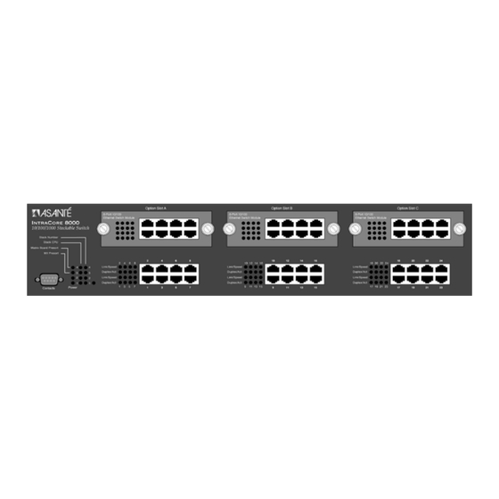
Installing Port Expansion Modules Up to three optional port expansion modules can be installed in the IntraCore 8000, in addition to a stack matrix module. (A stack matrix module is needed only if more than two units are stacked together. See “Stacking Switches.”) To install any combination of Gigabit Ethernet Switch (GBIC) modules and 8-port 10/100 Switch modules, use the following procedure. -
Page 26: Installing Gbic Interfaces
Installation and Setup Installing GBIC Interfaces If you have installed Gigabit Ethernet switch modules, you must install GBIC interfaces. Instructions for installing, removing, and maintaining GBIC interfaces are provided in this section. GBICs are hot-swappable. Note: Installing a GBIC To install a GBIC interface into a Gigabit Ethernet module: Remove the GBIC from its protective packaging. -
Page 27: Connecting Power
The most common source of contaminants in the optical bores is debris picked up from the optical connectors. Connecting Power To connect power to the IntraCore 8000, use the following procedure. Important: page 2-1 before connecting power to the IntraCore 8000. -
Page 28: Connecting To The Network
Installation and Setup Connecting to the Network The IntraCore 8000 unit may be connected to an Ethernet network, with the unit powered either on or off. Use the following procedure to make your network connections. Connect network devices to the IntraCore 8000, follow- ing the cable guidelines outlined below. -
Page 29: 1000Basex Ports Cabling Procedures
1000BaseLX GBIC Table 2-4 Configuring for Management To use the IntraCore 8000 as a managed switch, it must be configured with an IP address. This can be accomplished in one of two ways: automatically using BootP (default) manually via the unit’s Console port... -
Page 30: Connecting To A Console
Chapter 3, “Configuration.” To verify that a valid IP address was received, try to ‘ping’ the IntraCore 8000. If you can access the IntraCore 8000, it is properly configured with an IP address. For more information on using BootP, see “Bootstrap Configuration” in Chapter 3. -
Page 31: Management Options
Management management Software Table 2-5 The rest of this section describes how to connect to the IntraCore 8000 using either out-of-band or in-band management. Out-of-Band Management Out-of-band network management allows you to configure, manage, and monitor the IntraCore 8000 and all of the installed modules. You can... -
Page 32: In-Band Management
In-band network management allows you to configure, manage, and monitor the IntraCore 8000 over the Ethernet network. You can perform these functions by accessing the IntraCore 8000 via any of the following methods: By connecting with a telnet program and using the Local Manage- ment Interface. -
Page 33: Web Browser
Chapter 4, “Advanced Management,” and your SNMP software manual. The Asanté private MIB for the IntraCore 8000 is available from the Asanté ftp site, ftp.asante.com, or you can copy it from the Installation CD-ROM. Access to Remote Network Monitoring (RMON) features is available only by using an SNMP manager. - Page 34 Installation and Setup Page 2-16...
-
Page 35: Configuration
This chapter describes how to manage the IntraCore 8000 using the Local Management Interface via an out-of-band console connection or an in-band telnet connection. This chapter contains the following sections: Local Management Interface Viewing General Information Configuration Menu System Administration Configuration... -
Page 36: Local Management Interface
The Local Management Interface can be accessed via two methods: Out-of-band connection to the Console port In-band connection via Telnet (four sessions maximum) For instructions on how to connect to the IntraCore 8000, see “Management Options” on page 2-13. The rest of this chapter describes the Local Management Interface. -
Page 37: Main Menu
After logging in, the Main Menu appears, as shown in Figure 3-1. ================================================================= IntraCore 8000 Local Management System Version 1.02D Compiled Date: Jun 23 2000 19:53:29 Asante Technologies, Inc. Copyright (c) 1999 Asante Technologies, Inc. ================================================================= Main Menu <Cmd> <Description> General Information... -
Page 38: Viewing General Information
Viewing General Information The General Information Screen displays the current operating information of the IntraCore 8000, such as its name, IP address, and boot information. To view General Information, type g from the Main Menu. A screen similar to Figure 3-2 appears. - Page 39 The name assigned to the IntraCore for network purposes. The physical location of the IntraCore. Person responsible for configuration of the unit. The hardware address of the IntraCore 8000; this address can- not be changed The unit’s IP (Internet Protocol) address.
-
Page 40: Configuration Menu
Displays and allows you to change the name, location, and con- tact information for the IntraCore 8000. See page 3-8. Displays and allows changing the IP Address of the IntraCore 8000. This address is for network access to the switch. See page 3-9. - Page 41 3-45. Allows you to view a record of any major system events or errors that have occurred on the IntraCore 8000. See page 3-47 Allows you to set the idle time-out period and password when using console or telnet access. See page 3-49.
-
Page 42: System Administration Configuration
Setting System Name System Location System Contact Table 3-3 Changing System Administration Info To change the name, location, or contact information for the IntraCore 8000, use the following procedure. Page 3-8 Asante IntraCore Switch ZLabs Main Office Description The name of the IntraCore 8000 (up to 64 characters, including spaces). -
Page 43: System Ip Configuration
System IP Configuration The System IP Configuration Menu displays and allows you to change the information needed to access the IntraCore 8000 over the network via in- band management. To access the System IP Configuration Menu, type i in the Configuration Menu. -
Page 44: Current Settings
Page 3-10 Description The IP (Internet Protocol) address of the IntraCore 8000. The filter that determines how the IntraCore 8000 IP address is split into network and host portions. The IP address of the default router for the IntraCore 8000. -
Page 45: Bootstrap Configuration
Return to previous menu Command> Figure 3-6 Local Bootstrap Configuration Menu When the IntraCore 8000 is powered on, it loads its software via one of two methods: locally (via its internal flash memory, which is the default setting) or remotely over the network. -
Page 46: Loading Software Locally
Configuration Loading Software Locally The IntraCore 8000 will always boot locally unless you set it to boot load remotely. It would then download the new image code and reset to load locally. Open the Bootstrap Configuration Menu by typing b in the Configuration Menu. -
Page 47: Loading Software Remotely
Loading Software Remotely To set the IntraCore 8000 to download its software over the network from a remote server, use the following procedure. Open the Local Bootstrap Configuration Menu by typing b in Configuration Menu. Open the Remote Bootstrap Configuration Menu by typ- ing r in the Local Bootstrap Configuration Menu. - Page 48 TFTP (Trivial File Transfer Protocol). Important: To use this option, the IntraCore 8000 IP address must be set to 0.0.0.0. TFTP ONLY — Sets the IntraCore 8000 to only download the software image file through TFTP. Important: To use this option, the switch must already have an assigned IP address and the Load Mode must be set to Remote.
- Page 49 Remote, type l. The Local Bootstrap Configura- tion Menu appears, as shown in Figure 3-6. The IntraCore 8000 is now set to download its software remotely from the network. This will occur the next time the unit is powered on or reset.
-
Page 50: Snmp Configuration
This menu also allows you to specify which of your network management stations will receive traps from the IntraCore 8000. The s option in the Configuration Menu displays the SNMP (Simple... -
Page 51: Current Settings
Trap Authentication SNMP Trap Receivers Changing Community Strings To change the IntraCore 8000 community strings, use the following procedure. Open the SNMP Configuration Menu by typing n in the Configuration Menu. To change the read community string, type r. To change the write community string, type w. -
Page 52: Enabling Authentication Traps
They alert you when someone attempts to read or change data without the proper community string. To set the IntraCore 8000 to generate traps, use the following procedure. Open the SNMP Configuration Menu by typing n in the Configuration Menu. -
Page 53: Deleting A Trap Receiver
The trap receiver is deleted from the SNMP Trap Receivers list. Port Configuration The Port Configuration Menu allows you to manually configure each of the IntraCore 8000’s ports for port speed, duplex, and auto-negotiation. It also provides an overview of the entire IntraCore 8000 system’s port operating status. - Page 54 Configuration IntraCore 8000 Basic Port Configuration MenuModule Type: [24-100TX/RJ45] Module: [1] Operating Status: +---+--- Auto Negotiation: ******** Speed/Duplex: HHHHFHHH Port Status: Enabled Auto-Neg: Enabled[ABCD] <Cmd> <Description> Help for legends Toggle Port Status Enable/Disable Toggle Auto-Negotiation/Manual Toggle 10M/100M bps Link Speed...
-
Page 55: Viewing Legends For Configuration Settings
Viewing Legends for Configuration Settings To see legends explaining the symbols used for both the Basic and Global Port Configuration Menu settings, type h. A screen appears, as shown in Figure 3-11. Legends for port status: X - Absent - - Link down D - Disabled by Mgmt Action d - Disabled by Security Violation B - Blocking... -
Page 56: Current Port Settings
Configuration Current Port Settings The current module and port for which statistics are displayed is shown in the top right corner of the Port Configuration Menu. Table 3-7 describes each setting on the Port Configuration Menu. Setting Module Number Module Type Port Number Operating Status Auto Negotiation... -
Page 57: Configuring Auto-Negotiation
Access the Port Configuration Menu by typing p in the Configuration Menu. Choose a module in the System Module Map. To select the port you want to enable or disable, type s, n, or p in the Basic Port Configuration Menu. To toggle the port’s connection to either enabled or dis- abled status, type t. -
Page 58: Configuring A Port Manually
Configuration Configuring a Port Manually If you have changed the Auto Negotiation status of a port to Manual, as described in the previous section, you can toggle the link speed from 10Mbps to 100Mbps and back, and toggle the port from half to full duplex and back. -
Page 59: Configuring 1000Basex Ports
Figure 3-9. Enter the number of a module with 1000BaseX ports (such as module 2 in the map shown in Figure 3-9). The Port Configuration Menu for 1000BaseX ports appears, as shown in Figure 3-12. IntraCore 8000 Basic Port Configuration Menu Module: [1] Operating Status: Port Status: Enabled <Cmd>... - Page 60 Configuration Enabling or Disabling a Port Enabling or disabling a port is a manual operation. You can enable or disable a port to isolate network devices that may be causing problems on the network or to prevent unauthorized use of a port or station. To enable or disable a port, use the following procedure.
-
Page 61: Advanced Port Configuration
From the Port Configuration Menu, type a. The Advanced Port Configuration Menu appears for either 10/100BaseTX or 1000BaseX, as shown in Figure 3-13 and Figure 3-14. Advanced 10/100BaseTX Port Configuration IntraCore 8000 Advanced Port Config Menu Module: [1] Operating Status: Flow Ctrl: Priority: Max. - Page 62 Configuration Advanced 1000BaseX Port Configuration IntraCore 8000 Basic Port Configuration Menu Module: [1] Port: Flow Ctrl: Priority: Max. Broadcast Rate: Max. Multicast Rate: 802.3x Flow Control: Port Default Priority: <Cmd> <Description> Help for legends Set Max. Broadcast/Multicast Rate Toggle 802.3x Flow Control Enable/Disable...
-
Page 63: Current Settings
Current Settings The settings shown in the top portion of the Advanced Port Configuration Menu are described in Table 3-8. Setting Module Number Module Type Operating Status Flow Control Priority Max. Broadcast Rate Max. Multicast Rate Table 3-8 Setting the Maximum Broadcast or Multicast Rate Use the following procedure to set a limit on how many packets may be either broadcast or multicast from the current port. -
Page 64: Enabling Or Disabling 802.3X Flow Control
Configuration Use s, n, or p to select the port for which you want to set the broadcast or multicast rate. Type r to set the maximum broadcast or multicast rate for the selected port. Enter the rate for broadcast or multicast and press Return. The new maximum rate is displayed on the Advanced Port Configuration Menu. -
Page 65: Setting Port Default Priority
Setting Port Default Priority Use the following procedure to set the priority for a port. This priority setting determines the order in which the port forwards packets. Each port is associated with a traffic class: zero (0) is the lowest, and the default priority level. - Page 66 Configuration 10/100BaseTX ports or 1000BaseX ports, as shown in Figure 3-15 and Figure 3-16. IntraCore 8000 Global Port Configuration Menu Module: [1] Operating Status: Auto Negotiation: Link Speed/Duplex: Flow Ctrl: Priority: <Cmd> <Description> Help for legends Select Global Ports Status Enable/Disable...
-
Page 67: Unicast Forwarding Database Configuration
The IntraCore 8000 uses the information in this table to decide whether a frame should be forwarded to a particular destination port or “flooded” to all ports other than the received port. Each entry consists of three parts: the MAC address of the device, the port number on which it was received, and the VLAN number. -
Page 68: Current Settings
Type either a, p, or v, depending on the range of MAC addresses you want to view. Type a to display the MAC addresses of all ports on the IntraCore 8000. Type p to specify a port, then see the MAC addresses for that port only. - Page 69 M — multiple (associated with multiple IP addresses, as in the case of a router) I — Self (the IntraCore 8000’s MAC address) The Pri field refers to the priority setting for the port. The Age field indicates the amount of time remaining before an entry ages out.
-
Page 70: Searching For A Mac Address
Configuration Module: [1] Port: [6] Entry Type [T]: (D = Dynamic, S = Static, M = Multiple, I = Self) +-+-+-+-----------------+----------------+ |M|P|T| MAC Address +-+-+-+-----------------+----------------+ 1 6 D 00:00:94:10:80:1D 1 6 D 00:E0:52:01:44:46 1 6 D 00:00:94:A2:DE:56 1 6 D 00:00:94:7A:CF:48 1 6 D 00:00:94:92:F1:A8 - - I 00:00:94:8E:F2:CC 1 6 D 00:00:94:5D:E0:41... -
Page 71: Setting The Mac Address Age-Out Time
This option sets the Age-Out Time for the MAC Forwarding Table. The Age-Out Time is the number of seconds that addresses remain in the table after being learned by the IntraCore 8000. The default is 300 seconds. Use the following procedure to set the MAC address Age-Out Time. -
Page 72: Image File Downloading Configuration
X/Y/Z modem protocol. The two subsections that follow describe downloading by each of the two protocols. When Asanté issues a new version of software for the IntraCore 8000, you can obtain it from the Asanté World Wide Web site or by contacting Asanté... -
Page 73: Image Downloading Through Tftp
To download a new image file in-band through TFTP, type t in the Image File Downloading Configuration Menu (option g in the Configuration Menu). A screen similar to Figure 3-22 appears. IntraCore 8000 TFTP File Downloading Menu Bank 1 Image Version/Date Bank 2 Image Version/Date... - Page 74 1 on the IntraCore 8000. The version number and compilation date of runtime code that is stored in memory bank 2 on the IntraCore 8000. The (Run- ning) designation indicates that the runtime code is currently running on this bank.
-
Page 75: Performing A Software Upgrade At Runtime
Important: Make sure the IntraCore 8000 is configured with an IP address. For details, see “Changing System IP Information” earlier in this chapter. To upgrade the IntraCore 8000 software via TFTP, use the following procedure. Access the TFTP Image File Downloading Configuration Menu by typing t in the Image File Downloading Config- uration Menu. -
Page 76: Serial Downloading Configuration
Type q to return to the Image File Downloading Menu. Serial Downloading Configuration The X/Y/Z Modem Image File Downloading Menu lets you download a new software image file for the IntraCore 8000 without interrupting the current operation. To download a new image through the IntraCore 8000 management module’s serial (console) port, type x in the Image File Downloading... -
Page 77: Performing A Software Upgrade
Table 3-11 X/Y/Z Modem Image File Downloading settings Performing a Software Upgrade Use the following procedure to upgrade the IntraCore 8000 software through its serial (console) port. In the Image File Download Configuration Menu, type x to open the X/Y/Z Modem Image File Downloading Menu. - Page 78 K Note: The terminal on which the serial communica- tions software is running must have the same baud rate as the IntraCore 8000 management module con- sole. The connection from the terminal to the switch console port must be an RS232C straight-through cable.
-
Page 79: System Reset Configuration
System Reset Configuration The System Reset Configuration Menu allows you to reset the IntraCore 8000 by performing a “warm” reboot. It also allows you to schedule a reset up to 24 hours in advance. To reset the IntraCore 8000, type r in the Configuration Menu. A screen similar to Figure 3-25 appears. -
Page 80: Current Options
Open the System Reset Menu by typing r in the Configu- ration Menu. Type r, d or i. Typing r resets the IntraCore 8000. Typing d resets the IntraCore 8000 to the factory default. Typing i resets the IntraCore 8000 to the factory default without affecting its IP and Bootstrap configuration. -
Page 81: Scheduling A System Reset
Scheduling a System Reset You can schedule the IntraCore 8000 to automatically perform a reset from one second up to 24 hours (86,400 seconds) in advance. To schedule a reset, use the following procedure. Open the System Reset Menu by typing r in the Configu- ration Menu. -
Page 82: Clearing The System Log
Figure 3-27 System Log Summary The system log displays any major system events that have occurred on the IntraCore 8000. If no major events have occurred, “System up” messages are displayed. K Note: The system log holds a maximum of 64 entries. -
Page 83: User Interface Configuration
Local Management Interface, and enable or disable the Web server. To display the User Interface Configuration Menu, as shown in Figure 3-28, type u in the Configuration Menu. IntraCore 8000 User Interface Configuration Menu Console UI Idle Time Out Telnet UI Idle Time Out HTTP Server Status: ENABLED... - Page 84 Configuration Setting HTTP Server Status Telnet Session Status Telnet Session Source IP Table 3-13 Page 3-50 Description Enabled or Disabled. Inactive or Active, depending on whether session is in progress. The IP address of the device being used for telnet management. UI Time-out Settings...
-
Page 85: Setting Console Idle Time-Out Period
Setting Console Idle Time-out Period Use the following procedure to set the console idle time-out. Type c in the User Interface Configuration Menu. A prompt for the number of minutes is displayed. Enter the desired idle time-out in minutes. K Note: The default time-out is 5 minutes. Range for time-out is 0-60 minutes (0 indicates no time-out). -
Page 86: Enabling Or Disabling The Web Server
Viewing Statistics Viewing statistics on a regular basis allows you to evaluate your network’s performance. You can view current statistics for the IntraCore 8000 on a per- port basis and can change your view of those statistics and the counters displayed in it. - Page 87 Type s in the Local Management Interface Main Menu. The System Module Map is displayed, as shown in Figure 3-29. System Module Map ================= Please select one of the following slots Slot Description (Module Type) ---- ------------------------------- 24 10/100BaseTX ports Module (24-100TX) <none>...
- Page 88 Configuration IntraCore 8000 Port Statistics Counters Elapsed Time Since Up: <Counter Name> <Total> Total RX Pkts 1474 Dropped Pkts Good Multicast Oversize Pkts Fragments Collisions 64-Byte Pkts 128-255 Pkts 512-1023 Pkts <Cmd> <Description> since reset stop refresh quit Command> Figure 3-30 Port Statistics Counters since system up Use the s command to select a port for which you want to see the counters, or use n and p to find the port.
- Page 89 IntraCore 8000 Port Statistics Counters Elapsed Time Since Reset: <Counter Name> <Total> Total RX Pkts 1474 Dropped Pkts Good Multicast Oversize Pkts Fragments Collisions 64-Byte Pkts 128-255 Pkts 512-1023 Pkts <Cmd> <Description> since system up stop refresh quit Command> Figure 3-31 Port Statistics Counters since reset Type r to in the “since reset”...
- Page 90 Configuration Page 3-56...
-
Page 91: Advanced Management
This “closed path” or “bridged loop” among the networks can also start an unending packet-passing process. Important: To explain STP more effectively, the IntraC- ore 8000 is described as a bridge for this section of the manual. Page 4-1... -
Page 92: How It Works
Select the ports on each bridge that forward traffic, and place the redundant ports in blocking state. Enabling and Disabling STP The IntraCore 8000 is shipped with spanning tree enabled on all ports by default. To enable or disable STP on your IntraCore 8000, use the following procedure. -
Page 93: Configuring Spanning Tree Parameters
Configuring Spanning Tree Parameters To view the Spanning Tree Configuration Menu, as shown in Figure 4-1, type s in the Configuration Menu. IntraCore 8000 Spanning Tree Configuration Menu STP Status: Bridge ID: Designated Root: Root Port: Root Path Cost: Hello Time:... -
Page 94: Forward Delay
Advanced Management Maximum Age Each bridge should receive regular configuration BPDUs from the direction of the root bridge. If the maximum age timer expires before the bridge receives another BPDU, it assumes that a change in the topology has occurred, and it begins recalculating the spanning tree. Forward Delay After a recalculation of the spanning tree, the Forward Delay parameter regulates the delay before each port begins transmitting traffic. -
Page 95: Current Stp Settings
Whether spanning tree protocol is currently enabled or disabled. The Bridge Identifier of this bridge. The first part of the Bridge ID is the Bridge Priority. (If the Bridge ID is shown as 8000 000094EE5080, the 8000 is the Bridge Priority. The remainder is the MAC address of this bridge, which cannot be changed.). -
Page 96: Spanning Tree Port Configuration
To set the Port Priority and Port Path Cost values for STP, access the Spanning Tree Port Configuration Menu shown in Figure 4-2 by typing p in the Spanning Tree Configuration Menu. IntraCore 8000 Spanning Tree Port Config. Menu Module: [1] Port:... -
Page 97: Snmp And Rmon Management
Port Configuration Menu. SNMP and RMON Management The Simple Network Management Protocol (SNMP) may be used to manage the IntraCore 8000. The SNMP agent supports database objects that are defined in the following management information bases (MIBs): MIB II (RFC 1213) -
Page 98: Rmon Management
SNMP, as described in the previous section. The four groups of RMON that are supported by the IntraCore 8000 are described in the following sub-sections. -
Page 99: Security Management
For information on configuring trap receivers, see “SNMP Configuration” in Chapter 3. Security Management The IntraCore 8000’s security management options are summarized in Table 4-2. Security Option Duplicated IP Detec- tion (Monitoring) Duplicated IP Trap Station Movement Trap Port New Node Trap... -
Page 100: Current Settings
Advanced Management To access the Security Management Menu, type t in the Configuration Menu. A screen similar to Figure 4-3 appears. IntraCore 8000 Security Management Menu Duplicated-IP Monitoring Status: Enable Duplicated-IP Trap Status: Station Movement Trap Status: <Cmd> <Description> Port Security Configuration... -
Page 101: Duplicated Ip Detection And Trap
Type i to toggle duplicated IP trap. Viewing a List of Duplicated IP Addresses To view a list of duplicated IP addresses that have been detected at the IntraCore 8000: From the Configuration Menu, type t to access the Secu- rity Management Menu. -
Page 102: Enabling And Disabling Station Movement Trap
(if available) and the switch’s port numbers. By default, station movement trap is disabled. To enable or disable detection of the movement of a station on the IntraCore 8000: From the Configuration Menu, type t to access the Secu- rity Management Menu. -
Page 103: Configuring Port Security
Menu to access the Security Management Menu, then type p to access the Port Security Configuration Menu. A screen similar to Figure 4-5 appears. IntraCore 8000 Port Security Configuration Menu Module Type: [24-100TX/RJ45] Module: 01 Port: 01 Module Port Security Info:... -
Page 104: Configuring Port New Node Detection Trap
The new device is detected when it is connected to the IntraCore 8000 and its MAC address is recognized as one not present in the current address table. The information shown in the alert is the new node’s MAC address and IP address (if... -
Page 105: Configuring Port Lock And Intruder Lock
From the Configuration Menu, type t to access the Secu- rity Management Menu. Type p to access the Port Security Configuration Menu, as shown in Figure 4-5. Select u to Set/Clear port security. Type s to set security. Type the numbers of the ports for which you want to set the security. - Page 106 Advanced Management Note: The three security levels are mutually exclusive; a port can have either security level1, level2, or level 3, but never a combination of security levels. To configure security level 2 or 3, you must specify the port-trusted MAC address.
-
Page 107: Setting The Intruder Trap
Type i, then follow the instructions on the screen. Resetting Security to Defaults To reset the security measures on the IntraCore 8000 to the factory defaults, access the Security Management Menu by typing t in the Configuration Menu. Then type r to reset all of the security configurations that have been changed back to the factory-set defaults. -
Page 108: Vlan Management
IEEE 802.1Q standard. The following subsections describe the concepts and details needed to configure and manage VLANs on IntraCore switches. VLAN Specifications for the IntraCore 8000 The IntraCore 8000 supports the following features of the IEEE 802.1Q standard: Port-based VLAN management... -
Page 109: Other Vlan Features In Intracore 8000
Other VLAN Features in IntraCore 8000 VLAN management security VLAN MAC address insertion and removal Console UI management of VLANs Web interface management of VLANs The management operations allowed are: Creation Deletion Name configuration VID change configuration Adding and deleting port members... -
Page 110: Tagged And Untagged Frames
Advanced Management A VLAN localizes flooded traffic to parts of LAN segments rather than to a whole LAN. VLANs offer a simple and efficient solution that enhances network performance, bandwidth utilization, and network security by localizing flooded traffic. Port-based VLANs are the simplest of many VLAN approaches that solve the problem of unnecessary flooding. -
Page 111: Vlan Groups
“Configuring Inter-Switch Links.”) Default VLAN The IntraCore 8000 is configured by default with a single VLAN, with VID = 1; by default, all ports on the switch are assigned to VLAN 1. By default, the ports are also in the VLAN’s untagged set, which means they send only untagged frames. -
Page 112: Ingress Filtering
Advanced Management Port members can be added to and deleted from a VLAN Group via the VLAN Management Menu (see “Configuring Static VLAN Groups”). When you add it to a VLAN, you configure a port to determine its participation in the VLAN. -
Page 113: Inter-Switch Links
VLAN Management By default, independent learning of addresses is enabled. Under independent learning, all addresses learned in a VLAN are stored in an address table for that VLAN only, and all forwarding decisions for that VLAN are made by consulting that table. This can sometimes cause unexpected results if a port is a member of more than one VLAN. - Page 114 Advanced Management Switch 1 2 3 4 5 The configuration of the ISL ports and the other ports on each switch will determine how tagged frames are transmitted across the switches. For example, if you require frames from VLANs 2 and 3 to cross the switches, the ports should have the following configuration for both switches: Receive Port...
- Page 115 E-8. And because port 1 only accepts tagged frames, any untagged frames from E-9 will not cross from switch 2 to switch 1. If you want VLAN 2 to pass frames to and from E-9, you need to configure the ISL differently. For example, you could change port 1 on both switches as follows: Receive Port...
-
Page 116: Configuring Vlan Management
Number of Active VLANs: Description IEEE 802.1Q version number. Port-based or SNMP-based. The IntraCore 8000 supports 4094 VLAN IDs. The IntraCore 8000 supports 64 VLANs. Number of VLANs currently present on the switch. Number of VLANs currently active on the switch. -
Page 117: Configuring Static Vlan Groups
To access the VLAN Group Static Configuration Menu, type v in the Configuration Menu to access the VLAN Management Menu, then type s to access the VLAN Group Static Configuration Menu. A screen similar to Figure 4-8 appears. IntraCore 8000 VLAN Group Static Configuration Menu Module Port List ======... -
Page 118: Creating A Vlan
Advanced Management Current Settings Table 4-6 describes each setting on the Menu screen. Setting VLAN Index Port List Created By Mgm Access Name Status Table 4-6 Creating a VLAN To create a VLAN, you must first find a free VLAN index. From the VLAN Group Static Configuration Menu, type d. -
Page 119: Removing A Vlan
VLAN, then type e. Follow the instructions on the screen. Enabling and Disabling Management Access The IntraCore 8000 supports configurable management access for VLANs. By default, management access is enabled, and all devices connected to the switch in a VLAN can communicate with the switch management agent. -
Page 120: Advanced Static Vlan Configuration
Advanced Static VLAN Configuration To access the Advanced Group Static Configuration Menu, type v in the VLAN Group Static Configuration Menu. A screen similar to Figure 4-8 appears. IntraCore 8000 Advanced Group Static Config. Menu Module Port List ====== +: static... - Page 121 Current Settings Table 4-6 describes each setting on the Advance Group Static Configuration Menu screen. Setting VLAN Index Port List Created By Mgm Access Name Status Table 4-7 Specifying Tagging or No Tagging for a Port Each VLAN maintains a list of ports that do not send tagged frames. When you add a port member to a VLAN, it is added to the untagged set by default.
- Page 122 Advanced Management that VLAN only, and all forwarding decisions for that VLAN are made by consulting that table. When shared learning is enabled, a single forwarding table is used by all VLANs that are members of the shared group. (For more information, see “Independent vs.
-
Page 123: Configuring Vlan Port Attributes
Menu to access the VLAN Management Menu, then type p to access the VLAN Port Configuration Menu. A screen similar to Figure 4-10 appears. IntraCore 8000 VLAN Port Configuration Menu Module Type:[24-100TX/RJ45] Module: 01 Port: 01 Port VLAN Membership Info (+ : Member, -: Non Member):... - Page 124 PVID is meaningless and the port is assigned a PVID of 4095. Page 4-34 Description The IntraCore 8000 module for which the information on the screen applies. The port for which the information on the screen applies. Shows each VLAN index’s current membership status for this port.
- Page 125 Configuration Menu, type f to toggle port ingress filtering. Configuring Port Receive Frame Type By default, all ports on the IntraCore 8000 receive both 802.1Q tagged frames and untagged frames. A port may be configured to receive only 802.1Q tagged frames. This configuration is a necessary part of Inter-Switch Link (ISL) configuration (see “Configuring Inter-Switch Links”).
-
Page 126: Configuring Inter-Switch Links
Advanced Management Enabling and Disabling Port GVRP Status To enable or disable GVRP on the port, from the VLAN Port Configuration Menu, type g to toggle the port’s GVRP status. For GVRP to be active, GVRP must be active for Note: the system. - Page 127 Once you select a VLAN, type a. Then enter the module and port to assign to the VLAN. You specify module and port separated by a colon. For example, 1:8 assigns port 8 of module 1. Repeat steps 2 and 3 for each VLAN that is part of the ISL.
-
Page 128: Displaying A Summary Of Vlan Groups
To view a module port VLAN summary, type v in the Configuration Menu to access the VLAN Management Menu, then type m to access the Module Port VLAN Summary. A screen similar to Figure 4-12 appears. IntraCore 8000 Module 1 Port VLAN Info ======+======+============+==========+ Port | PVID |... -
Page 129: Displaying A Vlan Fid-Vid Association Summary
Figure 4-13 VLAN FID-VID association summary Resetting VLAN Configuration to Defaults To reset the security measures on the IntraCore 8000 to the factory defaults, access the VLAN Management Menu by typing v in the Configuration Menu. Then type r to reset all of the VLAN configurations that have been changed back to the factory-set defaults. - Page 130 To access the GVRP Configuration Menu, type v in the Configuration Menu to access the VLAN Management Menu, then type g to access the GVRP Configuration Menu. A screen similar to Figure 4-15 appears. IntraCore 8000 GVRP Configuration Menu VLAN[1] Id : 1 Dynamic Port Map Module...
- Page 131 Port List Table 4-9 Enabling and Disabling System GVRP To enable or disable GVRP on the IntraCore 8000, from the GVRP Configuration Menu, type t to toggle the status of system GVRP. Enabling GVRP on a Group of Ports To enable GVRP on a group of ports, from the GVRP Configuration Menu, type e.
- Page 132 VLAN Forbidden Set Configuration Menu, type f from the GVRP Configuration Menu. A screen similar to Figure 4-16 appears. Use the commands at the bottom of the menu to select a VLAN. IntraCore 8000 VLAN Forbidden Set Configuration Menu Module Port List...
- Page 133 Configuring Registration Fixed Sets To access the VLAN Registration Fixed Set Configuration Menu, type r from the GVRP Configuration Menu. A screen similar to Figure 4-17 appears. IntraCore 8000 VLAN Fixed Set Configuration Menu Module Port List ====== ======== +: Member...
-
Page 134: Multicast Traffic Management
Advanced Management Multicast Traffic Management Multicast traffic is a means to transmit a multimedia stream from the internet (a video conference, for example) without requiring a TCP connection from every remote host that wants to receive the stream. The stream is sent to the multicast address, and from there it’s propegated to all interested parties on the internet. -
Page 135: Igmp Snooping
Reservation Protocol (RSVP). RSVP allows an end station to reserve resources across the net in an attempt to maintain quality of service from a multicast provider. The IntraCore 8000 monitors RSVP messages so it can Multicast Traffic Management Page 4-45... -
Page 136: Configuring Multicast Traffic Management
The Multicast Traffic Management Menu allows you to set up group transmission. To access the Multicast Traffic Management Menu, type c in the Configuration Menu. A screen similar to Figure 4-18 appears. IntraCore 8000 Multicast Traffic Management Menu Multicast Forwarding Database -----------------------------... -
Page 137: Current Settings
Multicast Traffic Management Menu, type i to toggle the status of IGMP Snooping. Enabling and Multicast Poliocy-based Quality of Service To enable or disable QOS on the IntraCore 8000, from the Multicast Traffic Management Menu, type p to toggle the status of QOS. Displaying a Summary of Group Addresses To display a list of multicast group addresses, from the Multicast Traffic Management Menu, type d. -
Page 138: Multicast Forwarding Database Configuration
To access the Multicast FDB Configuration Menu, type c in the Configuration Menu to display the Multicast Traffic Management Menu. Then type m. A screen similar to Figure 4-20 appears. IntraCore 8000 Multicast FDB Configuration Menu Multicast Group Address: Created By: Priority: <Cmd>... - Page 139 Adding ports to the Selected Address To add or delete ports belonging to the multicast group: Select the VLAN that contains the ports and the address. Type v and follow the instructions. Select the Multicast Group address. Type s and follow the instructions.
- Page 140 Advanced Management Page 4-50...
-
Page 141: Web Browser Management
Web Browser Management This chapter tells how to manage the IntraCore 8000 by means of a Web browser, using Web pages to monitor and configure the switch. Most of the options and functions provided by Web browser management are similar to those of the Local Management Interface. For additional details about managing the IntraCore 8000, refer to Chapter 3, “Configuration,”... - Page 142 Web Browser Management Figure 5-1 Web Browser Management Overview page The Web Browser Management Overview page contains a sidebar with nine management option buttons, and a view of the IntraCore front panel that displays real-time IntraCore 8000 operating information. Page 5-2...
-
Page 143: Management Buttons
Management Buttons The buttons on the left provide the following options: Front Panel Genl Info (General Information) Statistics Port Config (Port Configuration) Span Tree (Spanning Tree Protocol Configuration) SNMP (Simple Network Management Protocol) Addr Table (IP/MAC Address Table) VLAN (Virtual LAN Configuration) Duplicate IP (Duplicate IP Trap Log) The following sections describe and explain the pages that are displayed when you click each of the buttons. - Page 144 Web Browser Management Port Selector Feature If you point the cursor to a port connector and click the mouse, a port- specific page is displayed, which shows the selected port’s configuration and traffic statistics. Figure 5-2 Port Configuration and Statistics page Page 5-4...
-
Page 145: Genl Info (General Information) Button
Genl Info (General Information) Button Genl Info (General Information) Button This button opens the IntraCore’s General Information page. The page has six sub-levels, which are listed at the top of Figure 5-3. The General Information fields are described fully in “User Interface Configuration” in Chapter 3. -
Page 146: Statistics Button
Web Browser Management Statistics Button This button opens the Statistics page, which presents a graphical image of the IntraCore statistics, as shown in Figure 5-4. On this page, the user can view system statistics since the last system reset. For a description of the statistics counters, see “Viewing Statistics”... - Page 147 ment counters were last reset or cleared. Reset – Clears the counters for future samplings. Counters – Displays the statistical counters of the associated view, since up or since reset, as shown in Figure 5-6 and Figure 5-7. Note: You may also view a summary of the frames per port by placing the cursor on the desired bar.
- Page 148 Web Browser Management In Figure 5-6, a summary of the counters for a port is displayed in table format. Figure 5-6 Summary of counters for a port In Figure 5-7 the counters for a port are displayed in bar graph form. Page 5-8...
- Page 149 Statistics Button Figure 5-7 Bar graph of counters for a port Page 5-9...
-
Page 150: Port Config (Port Configuration) Button
Web Browser Management Port Config (Port Configuration) Button This button opens the Port Configuration page, which provides a comprehensive overview of the status of each port on the IntraCore, as shown in Figure 5-8. The configuration page for any individual port can be accessed by single clicking on the associated blue number in the right or left hand margin. -
Page 151: Span Tree (Spanning Tree) Button
Span Tree (Spanning Tree) Button This button opens the Spanning Tree Protocol (STP) Configuration page, which shows the STP Configuration of the IntraCore, as shown in Figure 5- 9. STP configuration is explained in Chapter 4, “Advanced Management.” Click the STP Port Configuration button to display the STP Configuration settings for each port. -
Page 152: Snmp Button
Web Browser Management SNMP Button This button displays the SNMP (Simple Network Management Protocol) page, as shown in Figure 5-10. See “SNMP Configuration” in Chapter 3 for an explanation of SNMP settings. Figure 5-10 SNMP Configuration page Page 5-12... -
Page 153: Addr (Address) Table Button
Addr (Address) Table Button Addr (Address) Table Button The Addr Table button opens the MAC and IP Address Table page, which displays two tables, as shown in Figure 5-11. The top table displays the counts of IP and MAC addresses for each port. The lower table displays IP and MAC addresses for either a particular port, or all ports. -
Page 154: Vlan Button
VLAN Button This button opens the VLAN Groups page, as shown in Figure 5-12. The page shows the modules of the IntraCore 8000, and the ports that are assigned to the currently selected VLAN. There is also a panel that shows the VID of each VLAN on the current switch;... -
Page 155: Vlan Configuration
VLAN Button Figure 5-13 VLAN Port Selection page VLAN Configuration To congigure a VLAN, first select a VIDin the VLAN Groups page (Figure 5-12), then click the VLAN button. This opens the V LAN Group page, as shown in Figure 5-14. Configuration options Page 5-15... -
Page 156: Creating Or Modifying A Vlan
Web Browser Management Figure 5-14 VLAN Group Configuration options Creating or Modifying a VLAN To create or modify the basic attributes of a VLAN group, click the Create or Modify button in the VLAN Group Configuration dialog box. The VLAN Attributes dialog box is displayed, as shown in Figure 5-15. Figure 5-15 VLAN Attributes dialog box Enter or change the basic attributes, then click OK. - Page 157 the time you clicked VLAN in the VLAN Groups dialog page (Figure 5-12). You will see a dialog box asking you to confirm your decision to remove the VLAN. {{The above is total fiction. Is it right?}} Adding and Deleting Port Members To add ports to or delete ports from the current VLAN, click the Add/Del Members button in the VLAN Group Congiguration dialog box.
- Page 158 Figure 5-16 Add/Delete Port Member dialog box To add or delete MAC addresses for devices connected to the IntraCore 8000, click the Add/Del MAC Addr button in the VLAN Group Configuration dialog box. The dialog box shown in Figure 5-17 appears.
-
Page 159: Duplicate Ip Button
Duplicate IP Button Duplicate IP Button This button lights up if a duplicate IP number has been detected on the system. If you click the button, it opens the Duplicate IP Trap Log page which, if the trap is enabled, displays a record of duplicate IP Addresses detected. - Page 160 Web Browser Management Page 5-20...
-
Page 161: Technical Support
Contacting Technical Support To contact Asanté Technical Support: Telephone Fax-Back E-mail World Wide Web Site FTP site for RMON information Technical Support Hours 6:00 a.m. to 5:00 p.m. Pacific Standard Time USA, Monday - Friday. Technical Support (800) 622-7464 (801) 566-3787 (800) 741-8607 support@asante.com http://www.asante.com... - Page 162 Page A-2...
-
Page 163: Mib Statistics
MIB Statistics MIB Object Definitions for Counters The following MIB objects are those for which counters are displayed in the Statistics Counters screens shown in both the console and Web interface. The definitions and references are quoted from RFC 1516. Readable Frames "This object is the number of frames of valid frame length that have been received on this port. -
Page 164: Alignment Errors
minFrameSize and less than or equal to maxFrameSize (Ref: 4.4.2.1, IEEE 802.3 Std). The approximate minimum time for rollover of this counter is 80 hours." Reference: IEEE 802.3 Rptr Mgt, 19.2.6.2, aFrameCheckSequenceErrors Alignment Errors "This counter is incremented by one for each frame received on this port with the FCSError and FramingError signals asserted and CollisionEvent signal deasserted and whose OctetCount is greater than or equal to minFrameSize and less than or equal to maxFrameSize (Ref: IEEE 802.3... -
Page 165: Runts
MIB Object Definitions for Counters Implementors may wish to consider selecting the ShortEventMaxTime towards the lower end of the allowed tolerance range to accommodate bit losses suffered through physical channel devices not budgeted for within this standard. The approximate minimum time for rollover of this counter is 16 hours." Reference: IEEE 802.3 Rptr Mgt, 19.2.6.2, aShortEvents Runts "This counter is incremented by one for each CarrierEvent on this port that... -
Page 166: Late Events
Late Events "This counter is incremented by one for each CarrierEvent on this port in which the CollIn(X) variable transitions to the value SQE (Ref: 9.6.6.2, IEEE 802.3 Std) while the ActivityDuration is greater than the LateEventThreshold. Such a CarrierEvent is counted twice, as both a collision and as a lateEvent. - Page 167 MIB Object Definitions for Counters The LateEventThreshold is greater than 480 bit times and less than 565 bit times. LateEventThreshold has tolerances included to permit an implementation to build a single threshold to serve as both the LateEventThreshold and ValidPacketMinTime threshold. The approximate minimum time for rollover of this counter is 81 hours."...
- Page 168 Total Errors "The total number of errors which have occurred on this port. This counter is the summation of the values of other error counters (for the same port), namely: rptrMonitorPortFCSErrors, rptrMonitorPortAlignmentErrors, rptrMonitorPortFrameTooLongs, rptrMonitorPortShortEvents, rptrMonitorPortLateEvents, rptrMonitorPortVeryLongEvents, and rptrMonitorPortDataRateMismatches. This counter is redundant in the sense that it is the summation of information already available through other objects.
Need help?
Do you have a question about the IntraCore 8000 and is the answer not in the manual?
Questions and answers