Table of Contents
Advertisement
Advertisement
Table of Contents

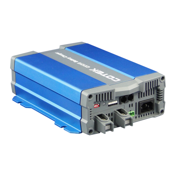
Summary of Contents for Cotek CX1215
- Page 1 CX-SERIES ADVANCED BATTERY CHARGER...
-
Page 3: Table Of Contents
3-6 Pin Assignment of CN3 – For Temperature sensor & Remote control ....... 12 3-7 Pin Assignment of CN4 – For Remote control) ..............12 3-8 Pin Assignment of ESB Connectors - For CX1215/1225/1235) ......... 13 3-9 Temperature Compensation ....................13 3-10 Rescue Battery Curve: ..................... -
Page 4: Important Safety Information
1. Important Safety Information WARNING! BEFORE INSTALLING OR USING CX-SERIES BATTERY CHARGER, YOU NEED TO READ FOLLOWING SAFETY INFORMATION CAREFULLY. 1-1 General Safety Precautions 1-1-1. For indoor use, do not expose CX-Series Battery Charger to water, mist, snow, or dust. To reduce the risk of fire, do not cover or obstruct the ventilation enclosure. 1-1-2. -
Page 5: Features
2. Features Universal AC input with active PFC Compatible with Lead Acid, Li-ion, Gel and AGM batteries Support remote controller CR-1 as optional accessory. Voltage / temperature compensation 2 stage fan speed control (Sleep mode) ... -
Page 6: Float Stage
2-1-2 Absorption Stage (Constant Voltage) The absorption charging duration will depend on the battery status. Before moving to absorption stage, charger will wait for two minutes then charging at constant voltage until the battery is fully charged. Once the battery is fully charged or the charging current is below 6.25% of the rated charging current for 15 minutes, then the absorption stage ends. -
Page 7: Specification
Sleep Mode By Remote Controller and S1-4 DIP switch (Please refer to section 3-2) Remote Controller Support COTEK Remote Controller CR-1 ( Please refer to section 3-6 and 3-7) Working Temp. -20~50°C (refer to output load de-rating curve) Working Humidity... -
Page 8: Mechanical Drawings
2-3 Mechanical Drawings Model: CX1215/1225/1235/2415 Unit: mm... - Page 9 Model: CX1250/1280/2425/2440 Unit: mm...
- Page 10 2-3-1 CX1215/1225/1235/2415 (Front Panel) Front panel ① ⑥ AC Inlet (IEC) Status LED ② ⑦ ESB connector ③ ⑧ DC output - TEMP/CN3 ④ ⑨ DC output + ⑤ Dip Switch 1 (S1) Note: For detail description on item 5 (Dip Switch S1), please refer to section 3-2...
- Page 11 2-3-3 CX1250/1280/2425/2440 (Front Panel) Front panel ① ⑤ AC Inlet (IEC) Status LED ② ⑥ DC output - ③ ⑦ DC output + TEMP/CN3 ④ ⑧ Dip Switch 1 (S1) Note: For detail description on item 4 (Dip Switch S1), please refer to section 3-2 2-3-4 CX1250/1280/2425/2440 (Rear Panel) Rear panel ①...
-
Page 12: Product Description
3. Product Description Below models are available with COTEK Advanced Battery Charger CX Series: Model No. of supply battery Support ESB (Engine Start battery) CX1215 CX1225 /CX1235 CX1250 /CX1280 CX2415 CX2425 /CX2440 3-1 Configurations 3-1-1 Standard Accessory Number Description Copper Bus... -
Page 13: S1 Dip Switch Setting
3-2 S1 Dip Switch Setting Status 12V / 24V CC/CV 12V / 24V Float 14.4V / 28.8V CC turn to CV voltage 14.7V / 29.4V 13.5V / 27.0V Float voltage 13.8V / 27.6V 13.2V / 26.4V Power Mode (Current limit 13.8V / 27.6V output voltage) 14.4V / 28.8V... -
Page 14: Failure Indicator
Red solid AC I/P unstable Output FUSE blown Battery over heat (the indicator is available only when COTEK temperature sensor is connected) Battery under heat ( the indicator is available only when Temperature Red fast COTEK temperature sensor is connected) -
Page 15: Pin Assignment Of Esb Connectors - For Cx1215/1225/1235)
3-8 Pin Assignment of ESB Connectors - For CX1215/1225/1235) 3-9 Temperature Compensation CX12xx Series model CX24xx Series model... -
Page 16: Rescue Battery Curve
The following curve is only applicable for Lead-acid & AGM battery. 3-11 Battery Charger Selection (Reference only) 12 Volt Battery COTEK Model Battery capacity range Estimated charging time CX1215 50~80Ah... -
Page 17: Battery Voltage Setting Suggestion
AGM TYPE (Max. Voltage of 14.4 / 28.8 Volt) Lead-Acid (Max. Voltage of 14.8 / 29.6 Volt) 4. Installing the COTEK Advanced Charger When selecting the installation location, observe the following instructions: The battery charger can be installed horizontally or vertically. -
Page 18: Battery Charger Connection Diagram
4-1 Battery charger connection diagram Model: CX1215 Single output charging CX1215 15A MAX Model: CX1225/CX1235/2415 CX-1225 25A MAX I1 + I2 CX-1235 35A MAX CX-2415 12.5A MAX... - Page 19 CX-1225 25A MAX I1 or I2 CX-1235 35A MAX CX-2415 12.5A MAX Model: CX1250/CX1280/2425/2440 CX-1250 50A MAX CX-1280 80A MAX I1+I2+I3 CX-2425 25A MAX CX-2440 40A MAX...
- Page 20 CX-1250 50A MAX CX-1280 80A MAX I1+I2 CX-2425 25A MAX CX-2440 40A MAX CX-1250 40A MAX CX-1280 40A MAX Single output CX-2425 25A MAX charging CX-2440 40A MAX CX-1250 40A MAX Single CX-1280 40A MAX output CX-2425 25A MAX charging CX-2440 40A MAX...
-
Page 21: Trouble Shooting
(Return material Authorization) service. Please note that COTEK is only responsible for ensuring our products are operational before delivery. This warranty will be considered void if the unit has been misused, altered, or accidentally damaged. COTEK is not liable for anything that occurs as a result of the user’s fault. - Page 22 No. 33, Sec. 2, Renhe Rd., Daxi Township, Taoyuan County 33548, Taiwan Phone:+886-3-3891999 FAX:+886-3-3802333 http:// www.cotek.com.tw Update: 2014.07...


Need help?
Do you have a question about the CX1215 and is the answer not in the manual?
Questions and answers