Table of Contents
Advertisement
www.nordictrack.com
Model No. NTL16914.0
Serial No.
Write the serial number in the space
above for reference.
Serial Number
Decal
ACTIVATE YOUR
WARRANTY
To register your product and
activate your warranty today, go
to www.nordictrackservice.com/
registration.
CUSTOMER CARE
For service at any time, go to
www.nordictrackservice.com.
Or call 1-800-TO-BE-FIT
(1-800-862-3348)
Mon.–Fri. 6 a.m.–6 p.m. MT
Sat. 8 a.m.–12 p.m. MT
Please do not contact the store.
CAUTION
Read all precautions and instruc-
tions in this manual before using
this equipment. Save this manual
for future reference.
USER'S MANUAL
Advertisement
Table of Contents

Related Manuals for NordicTrack C 630 NTL16914.0


Summary of Contents for NordicTrack C 630 NTL16914.0
- Page 1 Model No. NTL16914.0 Serial No. USER’S MANUAL Write the serial number in the space above for reference. Serial Number Decal ACTIVATE YOUR WARRANTY To register your product and activate your warranty today, go to www.nordictrackservice.com/ registration. CUSTOMER CARE For service at any time, go to www.nordictrackservice.com.
-
Page 2: Table Of Contents
Apply the decal in the location shown. Note: The decals may not be shown at actual size. 305284 NORDICTRACK is a registered trademark of ICON Health & Fitness, Inc. -
Page 3: Important Precautions
18. To purchase a surge suppressor, see your local 4. The treadmill is intended for home use only. NORDICTRACK dealer, call the telephone Do not use the treadmill in any commercial, number on the front cover of this manual, or rental, or institutional setting. - Page 4 20. Keep fingers, hair, and clothing away from or move the treadmill.When folding or mov- the moving walking belt. ing the treadmill, make sure that the storage latch is holding the frame securely in the 21. The treadmill is capable of high speeds. storage position.
- Page 6 STANDARD SERVICE PLANS...
-
Page 7: Before You Begin
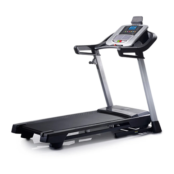
BEFORE YOU BEGIN Thank you for selecting the revolutionary reading this manual, please see the front cover of this NORDICTRACK C 630 treadmill. The C 630 treadmill manual. To help us assist you, please note the product ® offers an impressive selection of features designed model number and serial number before contacting us. -
Page 8: Part Identification Chart
PART IDENTIFICATION CHART Use the drawings below to identify small parts used for assembly. The number in parentheses below each draw- ing is the key number of the part, from the PART LIST near the end of this manual. The number following the key number is the quantity used for assembly. -
Page 9: Assembly
ASSEMBLY • Assembly requires two persons. • To identify small parts, see page 8. • Place all parts in a cleared area and remove the • Assembly requires the following tools: packing materials. Do not dispose of the packing the included hex key materials until you finish all assembly steps. - Page 10 2. Make sure that the power cord is unplugged. Wire Press a Base Cap (74) into each side of the Base (94). Next, remove the tie securing the Upright Wire (81) to the front of the Base (94). Identify the Right Upright (90). Have a second person hold the Right Upright near the Base (94).
- Page 11 4. Hold the Right Upright (90) against the Base (94). Be careful not to pinch the wires. Partially tighten three 3/8" x 4" Screws (7) with three 3/8" Star Washers (13) into the Right Upright and the Base; do not fully tighten the Screws yet.
- Page 12 6. Identify the left handrail assembly (A). Attach the left handrail assembly to the Left Upright (89) with two 5/16" x 2 1/2" Screws (28) and two 5/16" Star Washers (11); do not fully tighten the Screws yet. Then, remove and discard the indicated screw (B).
-
Page 13: Remove And Discard The Four Indicated Screws
8. Tighten four #8 x 3/4" Screws (2) into the left and right handrail assemblies (A, C) and into the Left and Right Uprights (89, 90). 9. Set the Console Base (64) face down on a soft surface to avoid scratching the Console Base. If there are ties securing the Pulse Crossbar (93) to the Console Base, remove the ties. - Page 14 10. Identify the Right and Left Trays (27, 36). Attach the Trays (27, 36) to the Console Base (64) with eight #8 x 1/2" Screws (1); do not overtighten the Screws. Reattach the Console Frame (18) with the six #8 x 3/4"...
- Page 15 12. With the help of a second person, hold the con- sole assembly near the Handrails (86) (only one Console side is shown). Assembly Connect the ground wire from the console assembly to the Console Ground Wire (58) on the Pulse Crossbar (93). Console See the inset drawing.
- Page 16 14. Attach the Pulse Crossbar (93) to the console assembly with four #8 x 1/2" Screws (1); start all Console four Screws, and then tighten them. Assembly Then, firmly tighten the four 5/16" x 3/4" Screws (4). 15. Firmly tighten the six 3/8" x 4" Screws (7) (only one side is shown).
- Page 17 17. Attach the Tablet Holder (53) to the back of the console assembly with four #8 x 1/2" Machine Screws (38); start all four Screws, and then tighten them. Be careful not to overtighten the Screws. Console Assembly 18. Make sure that all parts are properly tightened before you use the treadmill. If there are sheets of plastic on the treadmill decals, remove the plastic.
-
Page 18: How To Use The Treadmill
HOW TO USE THE TREADMILL HOW TO CONNECT THE POWER CORD nominal 120-volt circuit capable of carrying 15 or more amps. To avoid overloading the circuit, do Use a Surge Suppressor not plug other electrical devices, except for low- power devices such as cell phone chargers, into Your treadmill, like other electronic equipment, can be the surge suppressor or into an outlet on the same circuit. - Page 19 CONSOLE DIAGRAM FEATURES OF THE CONSOLE To turn on the power, see page 20. To use the man- ual mode, see page 20. To use an onboard workout, see page 22. To use a set-a-goal workout, see page The treadmill console offers an impressive array of 23.
- Page 20 HOW TO TURN ON THE POWER HOW TO USE THE MANUAL MODE IMPORTANT: If the treadmill has been exposed to 1. Insert the key into the console. cold temperatures, allow it to warm to room tem- perature before you turn on the power. If you do See HOW TO TURN ON THE POWER at the left.
- Page 21 4. Change the incline of the treadmill as desired. The My Trail tab will show a track that represents 1/4 mile (400 m). As you exercise, the flashing To change the incline of the treadmill, press the rectangle will show your progress. The My Trail tab Incline increase and decrease buttons or one of the will also show the number of laps you complete.
- Page 22 6. Measure your heart rate if desired. When you are finished using the treadmill, press the power switch into the off position and unplug Before using the the power cord. IMPORTANT: If you do not do this, the treadmill’s electrical components may handgrip heart wear prematurely.
- Page 23 4. Follow your progress with the displays. During the workout, the profiles on the See step 5 on page 21. If you select an onboard speed and workout, the display will show the time remaining incline tabs instead of the elapsed time. Current Segment will show your progress.
- Page 24 HOW TO USE AN IFIT WORKOUT The workout will continue until you reach the goal that you set. The walking belt will then slow to a stop. Note: To use an iFit workout, you must have access to a wireless network (see page 26). An iFit account is Note: The calorie goal is an estimate of the also required.
- Page 25 8. Turn on the fan if desired. When you select an iFit workout, the display will show the duration of the workout, the distance you will walk or run, and the approximate number of See step 7 on page 22. calories you will burn.
- Page 26 HOW TO CHANGE CONSOLE SETTINGS Units—The selected unit of measurement will appear in the matrix. To change the unit of mea- The console features a settings mode that allows you surement, press the Enter button. To view distance to view usage information, to personalize console set- in miles, select ENGLISH.
- Page 27 The WiFi–Advanced option will allow you to set up A list of networks will appear in the matrix. Press a wireless network connection using your com- the up and down buttons to highlight the desired puter, smart phone, tablet, or other Wi-Fi device. network.
- Page 28 5. Use WiFi–WPS to set up a wireless connection. Note: The network IFIT_SETUP will not appear if the console has already been configured to This option will allow you to set up a wireless net- connect to a wireless network. work connection using your WPS router.
- Page 29 HOW TO ADJUST THE CUSHIONING SYSTEM HOW TO USE THE TABLET HOLDER Remove the key from the console and unplug the You can use your tablet to browse media while you power cord. In order to adjust the cushions, you may exercise.
-
Page 30: How To Fold And Move The Treadmill
HOW TO FOLD AND MOVE THE TREADMILL HOW TO FOLD THE TREADMILL HOW TO MOVE THE TREADMILL To avoid damaging the treadmill, adjust the incline Before moving the treadmill, fold it as described at the to zero before you fold the treadmill. Then, remove left. -
Page 31: Maintenance And Troubleshooting
MAINTENANCE AND TROUBLESHOOTING MAINTENANCE SYMPTOM: The power turns off during use Regularly clean the treadmill and keep the walking a. Check the power switch (see drawing c at the left). belt clean and dry. First, press the power switch into If the switch has tripped, wait for five minutes and the off position and unplug the power cord. - Page 32 Locate the Reed Switch (52) and the Magnet (50) b. If the walking belt is overtightened, treadmill per- on the left side of the Pulley (49). Turn the Pulley formance may decrease and the walking belt may until the Magnet is aligned with the Reed Switch. become damaged.
- Page 33 SYMPTOM: The walking belt is off-center or slips b. If the walking belt slips when walked on, first when walked on remove the key and UNPLUG THE POWER CORD. Using the hex key, turn both idler roller a. If the walking belt is off-center, first remove the screws clockwise, 1/4 of a turn.
-
Page 34: Exercise Guidelines
EXERCISE GUIDELINES Burning Fat—To burn fat effectively, you must exer- WARNING: cise at a low intensity level for a sustained period of Before beginning this time. During the first few minutes of exercise, your or any exercise program, consult your physi- body uses carbohydrate calories for energy. -
Page 35: Part List
PART LIST Model No. NTL16914.0 R1114B Key No. Qty. Description Key No. Qty. Description #8 x 1/2" Screw Magnet #8 x 3/4" Screw Reed Switch Clip 1/4" Star Washer Reed Switch 5/16" x 3/4" Screw Tablet Holder #10 Star Washer Drive Motor 1/4"... -
Page 36: Exploded Drawing
EXPLODED DRAWING A Model No. NTL16914.0 R1114B... - Page 37 EXPLODED DRAWING B Model No. NTL16914.0 R1114B...
- Page 38 EXPLODED DRAWING C Model No. NTL16914.0 R1114B...
- Page 39 EXPLODED DRAWING D Model No. NTL16914.0 R1114B...
-
Page 40: Ordering Replacement Parts
ORDERING REPLACEMENT PARTS To order replacement parts, please see the front cover of this manual. To help us assist you, be prepared to provide the following information when contacting us: • the model number and serial number of the product (see the front cover of this manual) •...
Need help?
Do you have a question about the C 630 NTL16914.0 and is the answer not in the manual?
Questions and answers