Table of Contents
Advertisement
Advertisement
Table of Contents

Subscribe to Our Youtube Channel
Related Manuals for Risco RVCM11H


Summary of Contents for Risco RVCM11H
- Page 1 Cube Indoor IP Camera Model: RVCM11H Installation Guide...
- Page 2 Safety Precautions These instructions are intended to ensure that the user can use the product correctly to avoid danger or property loss. WARNINGS: Installation or usage of this product that is not in accordance with the intended use as defined by the supplier and as described in the instructional materials can result in damage, injury, or death.
-
Page 3: Table Of Contents
Connecting to a LAN Network ................. 6 Connecting to a Wireless Network using WPS ............7 Connecting to a Wireless Network using the RISCO Cloud ........7 IP Cameras and the RISCO Cloud Installer Application ..........8 Defining IP Camera Settings ..................8 Defining Camera Trigger Settings ................ -
Page 4: Safety Precautions
Powered by the RISCO Cloud (RISCO Application Server), VUpoint provides an unprecedented level of security and live video monitoring capabilities to monitoring stations and end-users alike. The RISCO cube indoor IP Camera is an important part of this solution and is easily controlled through RISCO’s intuitive Web and Smartphone applications. -
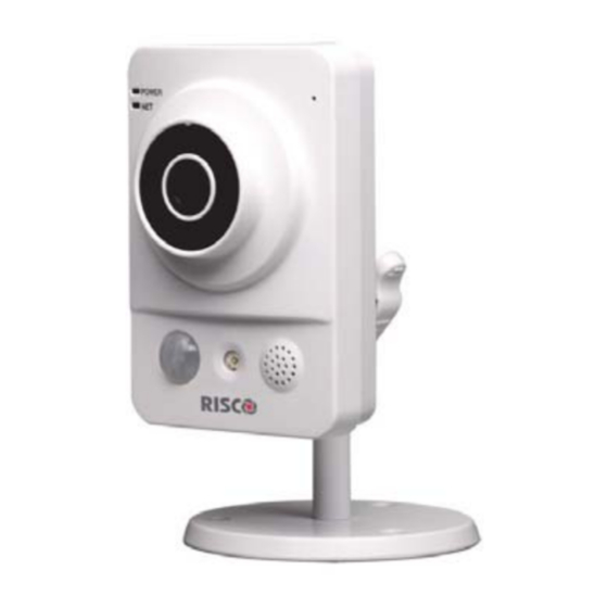
Page 5: Ip Camera Components And Dimensions
IP Camera Components and Dimensions Figure 1 IP Camera Components Label Port Name Indicator Connector Description Power POWER When camera boots up – Green indicator light turns on. light When camera is upgrading – Green light flashes. Interval is 0.5s. When camera is in alarm –... - Page 6 Label Port Name Indicator Connector Description Microphone Directly receive audio signal (This function is optional). Micro SD Micro Micro SD SD card storage. card card slot Micro SD card requirements: Type: class 4 Memory: up to 64GB. NOTE: Adding micro SD card enables the ability of recording video clips Reset Reset...
-
Page 7: Ip Camera Installation
IP Camera Installation After reading the installation instructions and before installing your IP camera, prepare a plan for mounting the IP camera at your protected site. Correct placement of your IP camera is crucial for optimal security-monitoring performance. First, determine which areas need to be protected and then map out the most optimal areas for installing your IP camera. -
Page 8: Powering-Up The Ip Camera
1. Connect the incoming network cable to the Network port on the IP camera. 2. Wait just a few minutes while the IP camera automatically connects to the RISCO Cloud. The RED network indicator light indicates that your IP camera is now ready for defining camera settings (Refer to Defining IP Camera... -
Page 9: Connecting To A Wireless Network Using Wps
(Refer to Defining IP Camera Settings). Connecting to a Wireless Network using the RISCO Cloud Connecting the IP camera to a wireless network using the RISCO Cloud (RISCO Application Server) requires that you first physically connect the IP camera to the router and then, from the RISCO Cloud Installer Application, define the IP camera settings and establish a wireless connection. -
Page 10: Ip Cameras And The Risco Cloud Installer Application
PC via the Web. This enables you to add IP cameras and define camera and event alarm trigger settings. IMPORTANT – A control panel must first be defined in RISCO Cloud in order to accept IP cameras and define camera settings (Refer to the RISCO Cloud... - Page 11 Select the partition(s) from the list of defined partitions Type Choose the RISCO camera type (for ON VIF or Generic camera type settings, refer to the RISCO Cloud Installer Application Manual) Enter the MAC address into this field. The MAC address (media access...
- Page 12 7. Click Add. If the “Camera was identified successfully” message is displayed, go straight to step 8. Figure 9 Camera was identified successfully message If an “unable to configure Internet Access”, “UPnP Client Error” or similar message is displayed, refer to the Troubleshooting section. NOTE –...
-
Page 13: Defining Camera Trigger Settings
11. Click OK to establish the wireless connection (Refer to Connecting to a Wireless Network using the RISCO Cloud). IMPORTANT – Once a wireless connection has been established, don’t forget to disconnect the IP camera Ethernet cable from the router. - Page 14 To define camera trigger settings: 1. From the Control Panel Cameras page, click the Triggers tab, the Camera Triggers List page is displayed. Figure 12 Camera Triggers List 2. Click Add Trigger; the Add Triggers dialog box appears. Figure 13 Add Trigger 3.
- Page 15 Additional fields are displayed in the Add Trigger dialog box according to the event type that you selected (see examples below for Partition and Detector event types). Figure 14 Add Partition Event Trigger Figure 15 Add Detector Event Trigger 4. Define the following fields in the Add Trigger dialog box according to the event type that you selected.
- Page 16 6. Once finished, click Done. The defined camera trigger is displayed in the Camera Triggers List page. Figure 16 Camera Triggers List NOTE – You also have the options to edit , create a duplicate , or to delete the selected camera trigger. IMPORTANT –...
-
Page 17: Troubleshooting
Troubleshooting Internet Configuration/UPnP Client Error Not all routers support UPnP and in some routers UPnP is disabled by default. If you have tried configuring internet access automatically and get the message “unable to configure Internet Access”, “UPnP Client Error” or similar, it should possible to set your IP cameras and router up manually. - Page 18 2. Once the Camera Interface Login page is displayed, enter the User and Password into the relevant fields and click Login. NOTE – By Default the User and Password for camera login is “admin” and “_AdmiN_+ camera MAC address” (e.g._AdmiN_AABBCCDDEEFF). 1.
- Page 19 NOTE: By default the TCP/IP settings should already be defined. 5. Click Save to save the changes. 6. Select Connection. The Connection Parameters page is displayed. Figure 20 Connection Parameters 7. Set the following port connection parameters of the camera: TCP Port Set the TCP port you want to define for the camera (in our example 47777).
- Page 20 2. Navigate to the Advanced Setup > Port Forwarding/Port Triggering. The Port Forwarding page is displayed. Figure 21 Port Forwarding page (empty) NOTE: This is the section in the router where we will specify which local IP address belongs to which external port number. Make sure that “Port forwarding”...
-
Page 21: Product Specification
Product Specification Performance Please refer to the following table for product performance specification. Parameter Main Processor TI Davinci high performance DSP Embedded LINUX Support real-time network monitor, local record, and remote operation at the System Resources same time. User Interface Remote operation interface such as WEB, DSS, PSS. - Page 22 Parameter 1-channel input and 1-channel output (on-off ) Alarm Port Support remote record only Manual>Video detect>Schedule Record Priority Support Micro SD card hot-swap SD Card Storage Support display network storage status Storage Management 1-channel wire Ethernet port, 10/100 Base-T Ethernet Wire Network IEEE802.11a/b/g/n, built-in antenna Wireless Network...
-
Page 23: Risco Group Limited Warranty
RISCO Group Limited Warranty RISCO Ltd. ,its subsidiaries and affiliates (the "Seller") warrants its products to be free from defects in materials and workmanship under normal use for 24 months from the date of production. Because the Seller does not install or connect the product, and because the product may be used in conjunction with products not manufactured by the Seller, the Seller cannot guarantee the performance of the security system which uses this product. -
Page 24: Contacting Your Installer / Supplier-Agent
Company logo: Other supplier-specific information: Contacting RISCO Group RISCO Group is committed to customer service and product support. You can contact us through our website (www.riscogroup.com) or at the following telephone and fax numbers: United Kingdom Belgium (Benelux) China (Shenzhen)
Need help?
Do you have a question about the RVCM11H and is the answer not in the manual?
Questions and answers