Table of Contents
Advertisement
Quick Links
Advertisement
Table of Contents

Related Manuals for Sans Digital ELITERAID ER316FD+B


Summary of Contents for Sans Digital ELITERAID ER316FD+B
- Page 1 ELITERAID ER316FD+B Detailed User’s Manual v 1.0...
- Page 2 Copyright No part of this publication may be reproduced, stored in a retrieval system, or transmitted in any form or by any means, electronic, mechanical, photocopying, recording or otherwise, without the prior written consent. Trademarks All products and trade names used in this document are trademarks or registered trademarks of their respective holders.
-
Page 3: About This Manual
About This Manual Welcome to your Redundant Array of Independent Disks System User’s Guide. This manual covers everything you need to know in learning how to install or configure your RAID system. This manual also assumes that you know the basic It includes the following information : concepts of RAID technology. -
Page 4: Table Of Contents
Table of Contents Chapter 1 Introduction Key Features......................RAID Concepts...................... Fibre Functions..................... 1-10 1.3.1 Overview....................... 1-10 1.3.2 Three ways to connect (FC Topologies)..........1-10 1.3.3 Basic elements..................1-12 1.3.4 LUNMasking....................1-13 ArrayDefinition....................... 1-13 1.4.1 RAID set......................1-13 1.4.2 Volume Set....................1-14 1.4.3 Easy of Use features.................. - Page 5 2.7.1 Create Volume Set..................2-30 2.7.2 Create Raid30/50/60..................2-33 2.7.3 Delete Volume Set..................2-34 2.7.4 Modify Volume Set..................2-35 2.7.4.1 Volume Expansion............... 2-35 2.7.5 Volume Set Migration.................. 2-37 2.7.6 Check Volume Set..................2-38 2.7.7 Scheduled Volume Checking..............2-39 2.7.8 Stop Volume Set Check................2-40 2.7.9 Volume Set Host Filters................
-
Page 6: Introduction
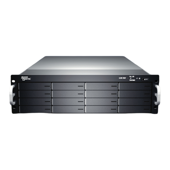
Chapter 1 Introduction The RAID subsystem is a Fibre channel-to-SAS / SATA II RAID (Redundant Arrays of Independent Disks) disk array subsystem. It consists of a RAID disk array controller and sixteen (16) disk trays. The subsystem is a “Host Independent” RAID subsystem supporting RAID lev- els 0, 1, 0+1, 3, 5, 6, 30, 50, 60 and JBOD. -
Page 7: Key Features
1.1 Key Features Subsystem Features: Features an Intel IOP341 800Mhz 64-BIT RISC I/O processor Build-in 512MB cache memory, expandable up to 4GB 4Gb Fibre channel, dual loop optical SFP LC (short wave) host port Smart-function LCD panel Supports up to sixteen (16) 1" hot-swappable SAS / SATA II hard drives Redundant load sharing hot-swappable power supplies High quality advanced cooling fans Local audible event notification alarm... -
Page 8: Raid Concepts
1.2 RAID Concepts RAID Fundamentals The basic idea of RAID (Redundant Array of Independent Disks) is to combine multiple inexpensive disk drives into an array of disk drives to obtain performance, capacity and reliability that exceeds that of a single large drive. The array of drives appears to the host computer as a single logical drive. - Page 9 By striping the drives in the array with stripes large enough so that each record falls entirely within one stripe, most records can be evenly distributed across all drives. This keeps all drives in the array busy during heavy load situations. This situation allows all drives to work concurrently on different I/O operations, and thus maximize the number of simultaneous I/O operations that can be performed by the array.
- Page 10 RAID 1 , also known as disk mirroring, is simply a pair of disk drives that store duplicate data but appear to the computer as a single drive. Although striping is not used within a single mirrored drive pair, multiple RAID 1 arrays can be striped together to create a single large array consisting of pairs of mirrored drives.
- Page 11 RAID 3 sector-stripes data across groups of drives, but one drive in the group is dedicated to storing parity information. RAID 3 relies on the embedded ECC in each sector for error detection. In the case of drive failure, data recovery is accomplished by calculating the exclusive OR (XOR) of the information recorded on the remaining drives.
- Page 12 RAID 6 is similar to RAID 5 in that data protection is achieved by writing parity information to the physical drives in the array. With RAID 6, however, two sets of parity data are used. These two sets are different, and each set occupies a capacity equivalent to that of one of the constituent drives.
- Page 13 Dual-level RAID achieves a balance between the increased data availability inherent in RAID 1 and RAID 5 and the increased read performance inherent in RAID 0+1 disk striping (RAID 0). These arrays are sometimes referred to as RAID 10 and RAID 0+5 or RAID 50. In summary: RAID 0 is the fastest and most efficient array type but offers no fault- tolerance.
-
Page 14: Raid Management
RAID Management The subsystem can implement several different levels of RAID technology. RAID levels supported by the subsystem are shown below. RAID Description Level Drives Block striping is provide, which yields higher performance than with individual drives. There is no redundancy. Drives are paired and mirrored. -
Page 15: Fibre Functions
1.3 Fibre Functions 1.3.1 Overview Fibre Channel is a set of standards under the auspices of ANSI (American National Standards Institute). Fibre Channel combines the best features from SCSI bus and IP protocols into a single standard interface, including high- performance data transfer (up to 400 MB per second), low error rates, multiple connection topologies, scalability, and more. - Page 16 The physical connection between devices varies from one topology to another. In all of these topologies, a transmitter node in one device sends information to a receiver node in another device. Fibre Channel networks can use any combi- nation of point-to-point, arbitrated loop(FC_AL), and switched fabric topologies to provide a variety of device sharing options.
-
Page 17: Basic Elements
network; each device can use the full available bandwidth. A fabric topology contains one or more switches connecting the ports in the FC network. The benefit of this topology is that many devices (approximately 2-24) can be connected. A port on a Fabric switch is called an F-Port (Fabric Port). -
Page 18: Lunmasking
nection to every connected device. Each node on a Switched fabric uses an aggregate throughput data path to send or receive data. 1.3.4 LUN Masking LUN masking is a RAID system-centric enforced method of masking multiple LUNs behind a single port. By using World Wide Port Names (WWPNs) of server HBAs, LUN masking is configured at the RAID-array level. -
Page 19: Volume Set
1.4.2 Volume Set A Volume Set is seen by the host system as a single logical device. It is orga- nized in a RAID level with one or more physical disks. RAID level refers to the level of data performance and protection of a Volume Set. A Volume Set ca- pacity can consume all or a portion of the disk capacity available in a RAID Set. - Page 20 tion and data on that raid set. If a server fails to work, the raid set disk drives can be moved to another server and inserted in any order. 1.4.3.3 Online Capacity Expansion Online Capacity Expansion makes it possible to add one or more physical drive to a volume set, while the server is in operation, eliminating the need to store and restore after reconfiguring the raid set.
- Page 21 The RAID subsystem controller redistributes the original volume set over the original and newly added disks, using the same fault-tolerance configuration. The unused capacity on the expand raid set can then be used to create an additional volume sets, with a different fault tolerance setting if user need to change.
-
Page 22: Highavailability
1.4.4 High availability 1.4.4.1 Creating Hot Spares A hot spare drive is an unused online available drive, which is ready for re- placing the failure disk drive. In a RAID level 1, 0+1, 3, 5, 6, 30, 50 or 60 raid set, any unused online available drive installed but not belonging to a raid set can define as a hot spare drive. - Page 23 matically and transparently rebuilds failed drives in the background with user- definable rebuild rates. The RAID subsystem will automatically restart the system and the rebuild if the system is shut down or powered off abnormally during a reconstruction procedure condition. When a disk is Hot Swap, al- though the system is functionally operational, the system may no longer be fault tolerant.
-
Page 24: Configuring
Chapter 2 Configuring The subsystem has a setup configuration utility built in containing important information about the configuration as well as settings for various optional functions in the subsystem. This chapter explains how to use and make changes to the setup utility. Configuration Methods There are three methods of configuring the subsystem. - Page 25 Note: You may connect a terminal while the subsystem’s power is on. Power-on the terminal. Run the VT100 program or an equivalent terminal program. Configuring...
- Page 26 The default setting of the monitor port is 115200 baud rate, 8 data bit, non-parity, 1 stop bit and no flow control.
- Page 27 Click disconnect button. Open the File menu, and then open Properties. Configuring...
- Page 28 Open the Settings Tab. Open the Settings Tab. Function, arrow and ctrl keys act as: Terminal Keys, Backspace key sends: Crtl+H, Emulation: VT100, Telnet terminal: VT100, Back scroll buffer lines: 500. Click OK.
- Page 29 Now, the VT100 is ready to use. After you have finished the VT100 Termi- nal setup, you may press “ X “ key (in your Terminal) to link the RAID subsystem and Terminal together. Press “X’ key to display the disk array Monitor Utility screen on your VT100 Terminal.
- Page 30 Main Menu The main menu shows all function that enables the customer to execute ac- tions by clicking on the appropriate link. Note: The password option allows user to set or clear the raid subsystem’s password protection feature. Once the password has been set, the user can only monitor and configure the raid subsystem by providing the cor- rect password.
- Page 31 VT100 terminal configuration Utility Main Menu Options Select an option and the related information or submenu items display beneath it. The submenus for each item are explained on the section 2.3. The configu- ration utility main menu options are: Option Description Quick Volume And Raid Set Create a RAID configurations which is...
-
Page 32: Configuring The Subsystem Using The Lcd Panel
2.2 Configuring the Subsystem Using the LCD Panel The LCD Display front panel function keys are the primary user interface for the Disk Array. Except for the “Firmware update” ,all configuration can be per- formed through this interface.The LCD provides a system of screens with ar- eas for information, status indication, or menus. -
Page 33: Menudiagram
2.3 Menu Diagram The following tree diagram is a summary of the various configuration and set- ting functions that can be accessed through the LCD panel menus or the termi- nal monitor. Raid 0 Greater Two TB Volume Support No, Use 64Bit LBA, use 4k Block Selected Capacity Select Stripe Size 4K,8K,16K,32K,64K,128K... - Page 34 Create Raid Set Select IDE Drives for Raid Set Ch01 ~ Ch016 Create Raid Set Yes, No Edit The Raid Set Name Delete Raid Set Select Raid Set To Delete Delete Raid Set Yes, No Are you sure? Yes, No Expand Raid Set Select IDE Drives for Raid Set Expansion Select Drives IDE Channel...
- Page 35 Create Volume Set Create Volume From Raid Set Volume Creation Greater Two TB Volume Support, Volume Name, Raid Level, Capacity, Stripe Size, Fibre Host#, LUN Base, Fibre LUN, Cache Mode, Tag Queuing Create Volume Yes, No Initialization Mode Foreground, Background, No Init Create Raid 30/50/60 Create Raid30/50/60 Free (capacity) Select multiple Raid Set to Create...
- Page 36 View Drive Information Select The Drives Create Pass Through Disk Select The Drives Fibre Host#, LUN Base, Fibre LUN, Cache Mode, Tag Queuing Modify Pass Through Disk Select The Drives Fibre Host#, LUN Base, Fibre LUN, Cache Mode, Physical Drives Tag Queuing Delete Pass Through Disk Select The Drives...
- Page 37 Channel 0 Speed Auto, 1Gb, 2Gb, 4Gb Channel 0 Topology Auto, Loop, Point-Point, Fabric Channel 0 Hard Loop ID Auto, 0 ~ 125 Fibre Channel Config Channel 1 Speed Auto, 1Gb, 2Gb, 4Gb Channel 1 Topology Auto, Loop, Point-Point, Fabric Channel 1 Hard Loop ID Auto, 0 ~ 125 DHCP Function...
-
Page 38: Web Browser-Based Remote Raid Management Via R-Link Ethernet
Web browser-based Remote RAID management via R- Link ethernet port Configuration of the internal RAID subsystem with remote RAID management is a web browser-based application, which utilizes the browser installed on your oper- ating system. Web browser-based remote RAID management can be used to man- age all the raid function. - Page 39 Main Menu The main menu shows all function that enables the customer to execute ac- tions by clicking on the appropriate link. Description Individual Category Create a RAID configuration, which is consist of Quick Function number physical disk installed; it can modify the volume set Capacity, Raid Level, and Stripe Size.
-
Page 40: Quick Create
Configuration Procedures Below are a few practical examples of concrete configuration procedures. Quick Create The number of physical drives in the raid subsystem determines the RAID levels that can be implemented with the raid set. You can create a raid set associated with exactly one volume set. - Page 41 Greater Two TB Volume Support: No: keep the volume size with max. 2TB limitation. 64bit LBA: max. size 512TB, for Unix or Linux. 4K Block: max. size 16TB, use with “basic disk “ under OS Window 2000, 2003 or XP. It cannot be used by with dynamic disk. Click on the Confirm The Operation and click on the Submit button in the Quick Create screen, the raid set and volume set will start to initialize.
-
Page 42: Raid Set Functions
Raid Set Functions Use the Raid Set Function and Volume Set Function if you prefer to customize your system. User manual configuration can full control of the raid set setting, will take longer complete than Quick Volume/Raid Setup configuration. Select the Raid Set Function to manually configure the raid set for the first time or deletes existing raid set and reconfigures the raid set. -
Page 43: Delete Raid Set
2.6.2 Delete Raid Set To delete a raid set, click on the Delete Raid Set link. A “Select The RAID SET To Delete” screen is displayed showing all raid set existing in the current controller. Click the raid set number you which to delete in the select column to delete screen. Click on the Confirm The Operation and click on the Submit button in the screen to delete it. -
Page 45: Expand Raid Set
2.6.3 Expand Raid Set Use this option to expand a raid set, when a disk is added to your system. This function is active when at least one drive is available. To expand a raid set, click on the Expand Raid Set link. Select the target raid set, which you want to expand it. - Page 46 Migrating occurs when a disk is added to a raid set. Migration status is dis- played in the raid status area of the Raid Set information when a disk is added to a raid set. Migrating status is also displayed in the associated volume status area of the volume set Information when a disk is added to a raid set.
- Page 47 Note: Cannot expand RaidSet when contains Raid30/50/60 volume. Configuring...
-
Page 48: Offline Raid Set
2.6.4 Offline Raid Set If user wants to move the Raid Set, when the RAID subsystem is power on. User can use the Offline Raid Set option to offline the raid set. To prevent removing the wrong drive, the disk LEDs will light when the Offline Raid Set is selected. -
Page 49: Activate Incomplete Raid Set
2.6.5 Activate Incomplete Raid Set When one of the disk drive is removed in power off state, the raid set state will change to Incomplete State. If user wants to continue to work, when the RAID subsystem is power on. User can use the Activate Raid Set option to active the raid set. - Page 50 Click on the Submit button in the screen to activate the raid set that has removed one of disk drive in the power off state. The RAID subsystem will continue to work in degraded mode.
-
Page 51: Create Hot Spare
2.6.6 Create Hot Spare When you choose the Create Hot Spare option in the Raid Set Function, all unused physical devices connected to the current controller appear: Select the target disk by clicking on the appropriate check box. Click on the Confirm The Operation, and click on the Submit button in the screen to create the hot spares. -
Page 52: Rescue Raid Set
2.6.8 Rescue Raid Set If you try to Rescue Missing RAID Set, please contact our engineer for assistance. -
Page 53: Volume Set Function
Volume Set Function A volume set is seen by the host system as a single logical device. It is orga- nized in a RAID level with one or more physical disks. RAID level refers to the level of data performance and protection of a volume set. A volume set capac- ity can consume all or a portion of the disk capacity available in a raid set. - Page 54 Volume Name: The default volume name will always appear as Volume ---VOL#. can rename the volume set name providing it does not exceed the 15 characters limit. Raid Level: Set the RAID level for the Volume Set. Highlight Raid Level and press Enter. The available RAID levels for the current Volume Set are displayed.
- Page 55 64bit LBA: the max. size 512TB, for Unix or Linux. 4K Block: the max. size 16TB , just use with “ basic disk manager “ under OS Window 2000, 2003 or XP. Noted that can’t be used by with dynamic disk manager.
- Page 56 LUN Base: Each fibre device attached to the Fibre card, as well as the card itself, must be assigned a unique fibre ID number. A Fibre channel can connect up to 126 (0 to 125) devices. The RAID subsystem is as a large Fibre device. We should assign an LUN base from a list of Fibre LUNs.
- Page 57 2.7.3 Delete Volume Set To delete Volume from raid set system function, move the cursor bar to the main menu and click on the Delete Volume Set link. The Select The Vol- ume Set To Delete screen will show all raid set number. Click on a raid set number and the Confirm The Operation and then click on the Submit button to show all volume set item in the selected raid set.
-
Page 58: Modify Volume Set
2.7.4 Modify Volume Set To modify a volume set from a raid set: (1). Click on the Modify Volume Set link. (2). Click on the volume set from the list that you wish to modify. Click on the Submit button. The following screen appears. - Page 59 Note: Cannot expand volume capacity in Raid30/50/60 volume. Configuring...
- Page 60 2.7.5 Volume Set Migration Migrating occurs when a volume set is migrating from one RAID level to another, a volume set strip size changes, or when a disk is added to a raid set. Migration status is displayed in the volume status area of the RaidSet Hierarchy screen when one RAID level to another, a Volume set strip size changes or when a disk is added to a raid set.
-
Page 61: Check Volume Set
2.7.6 Check Volume Set To check a volume set from a raid set: (1). Click on the Check Volume Set link. (2). Click on the volume set from the list that you wish to check. Click on Con- firm The Operation and click on the Submit button. Use this option to verify the correctness pf the redundant data in a volume set. -
Page 62: Scheduled Volume Checking
2.7.7 Scheduled Volume Checking To check a volume set by schedule : (1). Click on the Scheduled Volume Checking link. (2). Select desired schedule that you wish to check volume set. Click on Con- firm The Operation and click on the Submit button. Scheduler: Disabled, 1 Day(For Testing), 1Week, 2Weeks, 3Weeks, 4Weeks, 8Weeks, 12Weeks, 16Weeks, 20Weeks and 24Weeks. -
Page 63: Volume Set Host Filters
2.7.8 Stop VolumeSet Check Use this option to stop the Check Volume Set function. 2.7.9 Volume Set Host Filters Use this option to View/Edit Host Filters. Refer to section 2.9.2.2 View/Edit Volume Set Host Filters for more information. You should complete the Fibre Channel Configuration first before you use this option. -
Page 64: Physicaldrive
Physical Drive Choose this option from the Main Menu to select a physical disk and to per- form the operations listed below. 2.8.1 Create Pass-Through Disk To create pass-through disk, move the mouse cursor to the main menu and click on the Create Pass-Through link. The relative setting function screen appears. -
Page 65: Modify Pass-Through Disk
2.8.2 Modify Pass-Through Disk Use this option to modify the Pass-Through Disk Attribute. User can modify the cache mode, Tagged Command Queuing and Fibre channel/LUN Base/LUN on an existed pass through disk. To modify the pass-through drive attribute from the pass-through drive pool, move the mouse cursor bar to click on Modify Pass-Through link. -
Page 66: Delete Pass-Through Disk
2.8.3 Delete Pass-Through Disk delete pass-through drive from pass-through drive pool, move the mouse cursor bar to the main menus and click on Delete Pass Through link. After you complete the selection, Click on the Confirm The Operation and click on the Submit button to complete the delete action. -
Page 67: Identify Selected Drive
2.8.5 Identify Drive To prevent removing the wrong drive, the selected disk LED will light for physi- cally locating the selected disk when the Identify Drive is selected. To identify the selected drive from the drives pool, move the mouse cursor bar to click on Identify Drive link. -
Page 68: System Configuration
System Configuration 2.9.1 System Configuration To set the raid system function, move the cursor bar to the main menu and click on the Raid System Function link. The Raid System Function menu will show all items. Select the desired function. System Beeper Setting: The Alert Beeper function item is used to Disabled or Enable the RAID sub- system controller alarm tone generator. - Page 69 JBOD/RAID Configuration The RAID subsystem supports JBOD and RAID configuration. SATA NCQ Support: NCQ is a command protocol in Serial ATA that can only be implemented on native Serial ATA hard drives. It allows multiple commands to be outstanding within a drive at the same time.
- Page 70 Disk Write Cache Mode: The RAID subsystem supports auto, enabled and disabled. When the RAID sub- system with BBM (battery backup module) the auto option will Enable disk write cache. Contrariwise, the auto option will Disable disk write cache. Disk Capacity Truncation Mode: This RAID subsystem use drive truncation so that drives from differing vendors are more likely to be able to be used as spares for each other.
- Page 71 2.9.2 Fibre Channel Config To set the Fibre Channel function, move the cursor bar to the main menu and click on the Fibre Channel Config. The Raid System Fibre Channel Function menu will show all items. Select the desired function. Distinct WWNN for Each Channel Use this option to enable dual channel support on Mac machines.
-
Page 72: View/Edit Host Name List
Channel Speed Each FC Channel can be configured as 1 Gbps/sec, 2 Gbps/sec, 4 Gbps/sec or use “Auto” option for auto speed negotiation between 1G/4G. The controller de- fault is “Auto”, which should be adequate under most conditions. The Channel Speed setting takes effect for the next connection. - Page 73 1. Select WWN From Detected Host. 2. Key in: first enter the WWPN (exact 16 hex digits) of the host in the “Host WWN” text field. Optional host nick name (up to 23 ASCII characters) can be given for descriptive purpose. Choose “Add”...
- Page 74 2.9.2.2 Volume Set Host Filters Volume Set Host Filters can be specified by clicking “View/Edit Volume Set Host Filters” link at bottom of “Fibre Channel Config” page. Volume Set Host Filters can also be specified by clicking “Volume Set Functions” “Volume Set Host Filters”...
- Page 75 To add a host filter entry, first select the host to be include/exclude from Host WWN list. Adjust Range Mask, Filter Type, Access Mode fields. Choose “Add” operation, then Confirm/Submit to complete the add operation. The added host filter entry will be shown in the upper half of the Config Frame.
- Page 76 they can be combined as a single filter entry (using either WWN as host WWN) with Range Mask setting as 0xFFFFFFFF_FFFFFFFE. Note that under most circumstances, the Range Mask is left as 0xFFFFFFFF_FFFFFFFF, which means that only a single WWN is specified for that filter entry. Filter Type Each filter entry can be set to include or exclude certain host(s) from data access.
- Page 77 Configuring...
- Page 78 2.9.3 EtherNet Config To set the EtherNet function, move the cursor bar to the main menu and click on he EtherNet Config. The Raid System EtherNet Function menu will show all items. Select the desired function.
- Page 79 2.9.4 Alert By Mail Config To set the Event Notification function, move the cursor bar to the main menu and click on the Alert By Mail Config. The Raid System Event Notification Function menu will show all items. Select the desired function. When an abnormal condi- tion occurs, an error message will be email to administrator that a problem has occurred.
- Page 80 2.9.5 SNMP Configuration The SNMP gives users independence from the proprietary network management schemes of some manufacturers and SNMP is supported by many WAN and LAN manufacturers enabling true LAN/ WAN management integration. To set the SNMP function, move the cursor bar to the main menu and click on he SNMP Configuration.
- Page 81 the message. This allows user to easily define which RAID unit is having problem. Once this setting is done, alert by mail configuration will also work in the same way. SNMP Trap Notification Configurations: Select the desired function. After you complete the addition, Click on the Confirm The Operation and click on the Submit button to complete the action.
- Page 82 2.9.6 NTP Configuration NTP stands for Network Time Protocol, and it is an Internet protocol used to synchronize the clocks of computers to some time reference. NTP is an Internet standard protocol. You can directly type your NTP Server IP Address to have the RAID subsystem can work with it.
-
Page 83: View Events
2.9.7 View Events To view the RAID subsystem controller’s information, move the mouse cursor to the main menu and click on the System Information link. The Raid Sub- system events Information screen appears. Choose this option to view the system events information: Timer, Device, Event type, Elapse Time and Errors. - Page 84 2.9.8 Generate Test Events If you want to generate test events, move the cursor bar to the main menu and click on he Generate Test Events. Click on the Confirm The Operation, and click on the Submit button in the screen to create the hot spares. Then click on the View Events/Mute Beeper to view the test event.
-
Page 85: Clear Events Buffer
2.9.9 Clear Events Buffer Use this feature to clear the entire events buffer information. 2.9.10 Modify Password To set or change the RAID subsystem password, move the mouse cursor to Raid System Function screen, and click on the Change Password link. The Modify System Password screen appears. - Page 86 The password option allows user to set or clear the raid subsystem’s pass- word protection feature. Once the password has been set, the user can only monitor and configure the raid subsystem by providing the correct password. The password is used to protect the internal RAID subsystem from unautho- rized entry.
-
Page 87: Raidset Hierarchy
2.10 Information Menu 2.10.1 RaidSet Hierarchy Use this feature to view the internal raid subsystem current raid set, current vol- ume set and physical disk configuration. Click the volume set number you which to View in the select column. Then you can view the Volume Set Information and Fibre Channel Volume Set Host Filters. -
Page 88: System Information
2.10.2 System Information To view the RAID subsystem controller’s information, move the mouse cursor to the main menu and click on the System Information link. The Raid Subsystem Information screen appears. Use this feature to view the raid subsystem controller’s information. The control- ler name, firmware version, serial number, main processor, CPU data/Instruction cache size and system memory size/speed appear in this screen. -
Page 89: Hardware Monitor
2.10.3 Hardware Monitor To view the RAID subsystem controller’s hardware monitor information, move the mouse cursor to the main menu and click the Hardware Monitor link. The Hard- ware Information screen appears. The Hardware Monitor Information provides the temperature, fan speed (chassis fan) and voltage of the internal RAID subsystem. -
Page 90: Creating A New Raid Or Reconfiguring An Existing Raid
2.11 Creating a New RAID or Reconfiguring an Existing RAID You can configure raid sets and volume sets using Quick Create or Raid Set Functions/Volume Set Functions configuration method. Each configuration method requires a different level of user input. The general flow of operations for raid set and volume set configuration is: Step Action... -
Page 91: Appendix A Technical Specification
Appendix A Technical Specification RAID processor Intel IOP341 RISC RAID level 0, 1, 0+1, 3, 5, 6, 30, 50, 60 and JBOD Cache memory 512MB~4GB DDR2 ECC SDRAM No. of channels (host+disk) 2+16 FC-AL (4Gb/s * 2) Host bus interface Up to 400MB / sec Data transfer Drive bus interface...
Need help?
Do you have a question about the ELITERAID ER316FD+B and is the answer not in the manual?
Questions and answers