Table of Contents
Advertisement
Quick Links
Advertisement
Table of Contents

Related Manuals for Sans Digital ELITERAID ER208UT+B


Summary of Contents for Sans Digital ELITERAID ER208UT+B
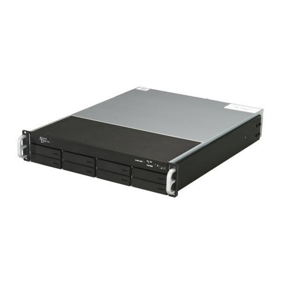
- Page 1 ELITERAID ER208UT+B DETAILED USER’S MANUAL v1.0...
-
Page 2: Fcc Statement
WARRANTY The information in this document is subject to change without notice. We make no warranty of any kind regarding this material, including, but not limited to, the implied warranties or merchantability and fitness for a particular purpose. Furthermore, we shall not be liable for errors con- tained herein or for incidental or consequential damage in connection with the furnishing, performance, or use of this material. -
Page 3: Table Of Contents
Contents 1. Introduction .............. 10 1.1 System Architecture ............10 1.1.1 eSATA/USB 2.0 Host Interface ........10 1.1.2 SATA ll Drive Interface ..........11 1.2 RAID Controller Controller Board ........11 1.2.1 Unparalleled Performance ..........11 1.2.2 Unsurpassed Data Availability ........12 1.2.3 Easy RAID Management .......... - Page 4 3.7.3.5 Activate Incomplete RaidSet ........33 3.7.3.6 Create Hot Spare Disk ..........33 3.7.3.7 Delete Hot Spare Disk ..........33 3.7.3.8 Display Raid Set Information ........33 3.7.4 Volume Set Functions ..........34 3.7.4.1 Create Raid Volume Set ..........35 3.7.4.1.1 Volume Name .............35 3.7.4.1.2 Raid Level ............35 3.7.4.1.3 Stripe Size ............35 3.7.4.1.4 Cache Mode ............36 3.7.4.1.5 Host Channel............36...
- Page 5 3.7.6.15 Terminal Port Configuration ........49 3.7.6.16 Shutdown The Controller........50 3.7.6.17 Restart The Controller ...........50 3.7.7 Ethernet Configuration ..........50 3.7.7.1 DHCP ..............50 3.7.7.2 Local IP Adress ............51 3.7.7.3 HTTP Port Number ..........51 3.7.7.4 Telnet Port Number ..........51 3.7.7.5 SMTP Port Number ..........52 3.7.7.6 Ethernet Address ............52 3.7.8 Show System Events ...........52 3.7.9 Clear all Event Buffers ..........52...
- Page 6 4.5.3.2 Delete Volume Set ..........78 4.5.3.3 Modify Volume Set ..........79 4.5.3.3.1 Volume Expansion ..........79 4.5.3.3.2 Volume Set Migration ..........80 4.5.3.4 Check Volume Set ...........81 4.5.3.5 Stop Volume Set Check ...........81 4.5.4 Physical Drives ............82 4.5.4.1 View Drive Information ...........83 4.5.4.2 Create Pass-Through Disk ........83 4.5.4.3 Modify Pass-Through Disk ........84 4.5.4.4 Delete Pass-Through Disk ........84 4.5.4.5 Identify Selected Drive ..........84...
- Page 7 4.5.10 System Information ..........105 5. Web Browser-based Configuration ......106 5.1 Firmware-embedded TCP/IP & web browser-based RAID man- ager (using the controller’s 10/100 LAN port) ......107 5.2 Web Browser Start-up Screen ......... 107 5.2.1 Main Menu ............... 108 5.3 Quick Function ...............
- Page 8 5.7.8 Clear Events Buffer ............ 130 5.7.9 Modify Password ............130 5.7.10 Upgrade Firmware ........... 131 5.7.11 Shutdown Controller ..........131 5.7.12 Restart Controller ........... 131 5.8 Information Menu ............132 5.8.1 RaidSet Hierarchy ............132 5.8.2 System Information ........... 132 5.8.3 Hardware Monitor ............
- Page 9 • Auto Reassign Sector ............153 • Consistency Check ............154 Data Protection ..............154 • Recovery ROM ..............154 Appendix F ..............156 Understanding RAID ............156 RAID 0 ................156 RAID 1 ................157 RAID 10(1E) ..............158 RAID 3 ................
-
Page 10: Introduction
INTRODUCTION 1. Introduction The EliteRAID RAID Storage Subsystem is a high-performance SATA ll drive bus disk array controller. When properly configured, the RAID conntroller can provide non-stop service with a high degree of fault tolerance through the use of RAID technology and advanced array management features. -
Page 11: Sata Ll Drive Interface
400MHz storage processors and on-board DDR2-400 SDRAM memory to deliver true hardware RAID. Designed and leveraged with Sans Digital’s existing high performance solution, this controller delivers high-capacity performance at the best of cost/ performance value. Hardware RAID conntroller have their own local RAID processor onboard, plus dedicated onboard cache for full hardware offloading of RAID-processing functions. -
Page 12: Unsurpassed Data Availability
Hot Swap, Online Background Rebuilding, Instant Availability/ Background Initialization, Auto Reassign Sector and Redundant Flash Image. Sans Digital greater than two TB support allows for very large volume set application in 64-bit environment such as data- mining and managing large databases. - Page 13 INTRODUCTION • Multiple RAID selection • Up to 16 volumes per RAID controller (port multiplier SATA host: 8 volumes, without port multiplier SATA host: 1 volume and USB 2.0:16 volumes) • Online array roaming • Online RAID level/stripe size migration •...
-
Page 14: Configuration Methods
CONFIGURATION METHOD 2. Configuration Methods After the hardware installation, the SATA disk drives connected to the RAID controller must be configured and the volume set units initialized before they are ready to use. This can be accomplished by one of the following methods: •... -
Page 15: Configuration Method
CONFIGURATION METHOD A touch-control keypad and a liquid crystal display (LCD) mounted on the back panel of the RAID controller is the primary operational interface and monitor display for the disk array controller. This user interface controls all configuration and management functions for the RAID controller it is properly connected. -
Page 16: Vt100 Terminal (Using The Controller's Serial Port)
CONFIGURATION METHOD For additional information on using the LCD panel and keypad to configure the RAID controller see ‘‘LCD Configuration Menu” on Chapter 4. 2.2 VT100 terminal (Using the controller’s serial port) The serial port on the RAID controller’s back panel can be used in VT100 mode. -
Page 17: Start-Up Vt100 Screen
CONFIGURATION METHOD Keyboard Navigation The following definition is the VT-100 RAID configuration utility keyboard navigation. Function Arrow Key Move cursor Enter Key Submit selection function ESC Key Return to previous screen L Key Line draw X Key Redraw 2.2.2 Start-up VT100 Screen By connecting a VT100 compatible terminal, or a PC operating in an equivalent terminal emulation mode, all RAID controller moni- toring, configuration and administration functions can be exer-... - Page 18 CONFIGURATION METHOD Step 3. Select an appropriate connecting port in your Terminal. Click OK. Configure the port parameter settings. Bits per second: “115200”, Data bits: “8”, Parity: ”None”, Stop bits: “1”, Flow control:” None”. Click “OK” Step 4. Open the File menu, and then open Properties. Step 5.
- Page 19 CONFIGURATION METHOD Step 6. Open the Settings Tab. Function, arrow and ctrl keys act as: Terminal Keys, Backspace key sends: “Crtl+H”, Emulation: VT100, Telnet terminal: VT100, Back scroll buffer lines: 500. Click Now, the VT100 is ready to use. After you have finished the VT100 Terminal setup, you may press “...
-
Page 20: Web Browser-Based Raid Manager
CONFIGURATION METHOD 2.3 Web browser-based RAID manager To configure EliteRAID RAID controller a local or remote machine, you need to know its IP Address. The IP address will default show in the LCD screen or Ethernet Configuration option on the VT100 utility configration. - Page 21 CONFIGURATION METHOD Note: Ethernet Configuration, Alert By Mail Config, and SNMP Config can only be set in the web-based configuration.
-
Page 22: Lcd Configuration Menu
LCD CONFIGURATION MENU 3. LCD Configuration Menu After the hardware installation, the disk drives connected to the RAID controller must be configured and the volume set units initialized before they are ready to use. This can be also accomplished by the rear panel touch-control keypad. -
Page 23: Lcd Configuration Utility Main Menu Options
LCD CONFIGURATION MENU 3.2 LCD Configuration Utility Main Menu Options Select an option, related information or submenu items to display beneath it. The submenus for each item are explained on the sec- tion 3.7.2. The configuration utility main menu options are: Option Description Quick Volume And Raid Set... -
Page 24: Designating Drives As Hot Spares
LCD CONFIGURATION MENU 3.4 Designating Drives as Hot Spares To designate drives as hot spares, press ENT to enter the Main menu. Press UP/DOWN buttons to select the “Raid Set Functions” option and then press ENT. All raid set functions will be displayed. Press up and down arrow to select the “Create Hot Spare Disk”... - Page 25 LCD CONFIGURATION MENU Recommend use drives have same capacity in a specific array. If you use drives with different capacities in an array, all drives in the raid set will select the lowest capacity of the drive in the raid set. The numbers of physical drives in a specific array determine the RAID levels that can be implemented with the array.
-
Page 26: Using Raid Set And Volume Set Functions
LCD CONFIGURATION MENU 3.6 Using Raid Set and Volume Set Func- tions In “Raid Set Function”, you can use the create raid set function to generate the new raid set. In “Volume Set Function”, you can use the create volume set function to generate its associated volume set and parameters. -
Page 27: Navigation Map Of The Lcd
LCD CONFIGURATION MENU Press ENT when you are finished creating the current raid set. To contin- ue defining another raid set, repeat step 3. To begin volume set configu- ration, go to step 8. Choose “Volume Set Functions” from the Main menu. Select the “Create Volume Set”... - Page 28 LCD CONFIGURATION MENU Figure 3.7-1 3.7.1 One-step creation Using LCD Hot Key This section explains how to use the LCD Hot-Key one-step creation RAID configuration to configure your EliteRAID RAID controller. It is a menu-driven program, residing in the firmware, which allows you to scroll through various menus and submenus and select among the predetermined configuration options.
-
Page 29: One-Step Creation Using Lcd Hot Key
LCD CONFIGURATION MENU The LCD configuration manager starts the Hot-Key one-step creation RAID configuration by pressing DOWN button three times. If you do not use the one-step creation, press ENT to start the main menu of LCD configuration immediately. The figure 3.7.1-1 is the flow chart of the Hot-Key one-step creation RAID configuration. -
Page 30: Raid Set Functions
LCD CONFIGURATION MENU Figure 3.7.2-1 1. All of the physical disk drives are contained in a raid set. 2. The raid levels associated with hot spare, capacity, and stripe size are selected during the configuration process. 3. A single volume set is created and consumed all or a portion of the disk capacity available in this raid set. -
Page 31: Create A New Raid Set
LCD CONFIGURATION MENU Figure 3.7.3-1 3.7.3.1 Create A New Raid Set For detailed procedure please refer to chapter section 3.6. 3.7.3.2 Delete Raid Set Press UP/DOWN buttons to choose the “Delete Raid Set” op- tion. Using UP/DOWN buttons to select the raid set number that user want to delete and then press ENT to accept the raid set number. -
Page 32: Expand Raid Set
LCD CONFIGURATION MENU 3.7.3.3 Expand Raid Set Instead of deleting a raid set and recreating it with additional disk drives, the “Expand Existed Raid Set” function allows the user to add disk drives to the raid set that was created. To expand existed raid set, press UP/DOWN buttons to choose the “Expand Raid Set”... -
Page 33: Activate Incomplete Raidset
LCD CONFIGURATION MENU 3.7.3.5 Activate Incomplete RaidSet When one of the disk drive is removed in power off state, the raid set state will change to Incomplete State. If user wants to continue to work, when the RAID controller is power on. User can use the “Activate Incomplete RaidSet”... -
Page 34: Volume Set Functions
LCD CONFIGURATION MENU 3.7.4 Volume Set Functions A volume set is seen by the host system as a single logical de- vice. It is organized in a RAID level with one or more physical disks. RAID level refers to the level of data performance and protection of a volume set. -
Page 35: Create Raid Volume Set
LCD CONFIGURATION MENU Figure 3.7.4.1-1 3.7.4.1.1 Volume Name The default volume name will always appear as Volume Set. #. You can rename the volume set name providing it does not exceed the 15 characters limit. 3.7.4.1.2 Raid Level The RAID controller can support raid level 0, 1, 10, 1E, 3, 5 or 6. -
Page 36: Cache Mode
LCD CONFIGURATION MENU 3.7.4.1.4 Cache Mode User can set the cache mode as Write-Through Cache or Write- Back Cache. 3.7.4.1.5 Host Channel There are two kinds of host map to two internal channels for each volume. Different channel host can map to and access the same volume. -
Page 37: Sata Xfer Mode
LCD CONFIGURATION MENU Up to 16 volumes can support on each EliteRAID RAID controller. When both hosts map to the same volume, select both host allowable drive number for this volume. If you can’ t map both host on the same driver number, then you can not map both host to same volume. -
Page 38: Delete Existed Volume Set
LCD CONFIGURATION MENU 3.7.4.2 Delete Existed Volume Set Choose the "Delete Existed Volume Set" option. Using UP/ DOWN buttons to select the raid set number that user want to delete and press ENT. The confirmation screen appears, and then press ENT to accept the delete volume set function. The double confirmation screen appears, then press ENT to make sure of the delete volume set function. -
Page 39: Volume Set Migration
LCD CONFIGURATION MENU Press ENT to select the existed volume set attribute. The vol- ume set attributes screen shows the volume set setting configu- ration attributes that was currently being configured. The at- tributes are Raid Level, Stripe Size, Cache Mode, Host Channel, Drive Number, SATA Xfer Mode and Volume Name (number). -
Page 40: Physical Drive Functions
LCD CONFIGURATION MENU set number that user wants to show and press ENT. The volume set information will show Volume Set Name, Raid Set Name, Volume Capacity, Volume State, HOST/Drv Setting, Raid Level, Stripe Size, Member Disks, Cache Attribute, SATA Xfer Mode and Current SATA. -
Page 41: Display Drive Information
LCD CONFIGURATION MENU Figure 3.7.5-2 3.7.5.1 Display Drive Information Using UP/DOWN buttons to choose the “Display Drive Informa- tion” option and press ENT. Using UP/DOWN buttons to select the drive IDE number that user want to display. The drive infor- mation will be displayed. -
Page 42: Modify Pass Through Disk
LCD CONFIGURATION MENU All values can be changed by user. Press the UP/DOWN buttons to attribute and then press ENT to modify the default value. Us- ing the up and down arrow buttons to select attribute value and press ENT to accept the selection value. 3.7.5.3 Modify Pass Through Disk To modify Pass Through Disk attributes from Pass Through drive pool, press UP/DOWN buttons to choose the “Modify Pass... -
Page 43: Raid System Functions
LCD CONFIGURATION MENU To identify selected drive from the physical drive pool, press UP/DOWN buttons to choose the “Identify The Selected Drive” option, then press ENT key. The Select Drive function menu will show all physical drive number items. Using UP/DOWN buttons to select the disk that user want to identify and press ENT. - Page 44 LCD CONFIGURATION MENU Figure 3.7.6-1...
-
Page 45: Mute The Alert Beeper
LCD CONFIGURATION MENU 3.7.6.1 Mute The Alert Beeper The “Mute The Alert Beeper” function item is used to control the RAID controller beeper. Select No and press ENT button to turn the beeper off temporarily. The beeper will still activate on the next event. -
Page 46: Raid Rebuild Priority
LCD CONFIGURATION MENU 3.7.6.5 Raid Rebuild Priority The “Raid Rebuild Priority” is a relative indication of how much time the controller devotes to a rebuild operation. The RAID controller allows user to choose the rebuild priority (UltraLow, Low, ... High) to balance volume set access and rebuild tasks appropriately. -
Page 47: Hdd Read Ahead Cache
LCD CONFIGURATION MENU Disable: No NCQ support ESB2/MACPro/Siliconlimage: Intel ESB2, MACPro and Siliconimage SATA controller ICH: Intel ICH series SATA controller Marvell6145: Marvell 6145 SATA controller nVidia: Nvida SATA controller 3.7.6.8 HDD Read Ahead Cache Allow Read Ahead (Default: Enabled)—When Enabled, the drive’s read ahead cache algorithm is used, providing maximum perfor- mance under most circumstances. -
Page 48: Spin Down Idle Hdd
This function is disabled by default. 3.7.6.14 Disk Capacity Truncation Mode Sans Digital RAID controller use drive truncation so that drives from differing vendors are more likely to be able to be used as spares for each other. Drive truncation slightly decreases the usable... -
Page 49: Terminal Port Configuration
LCD CONFIGURATION MENU capacity of a drive that is used in redundant units. The RAID controller provides three truncation modes in the system configuration: Multiples Of 10G, Multiples Of 1G and No Truncation. Multiples Of 10G: If you have 120 GB drives from different vendors;... -
Page 50: Shutdown The Controller
LCD CONFIGURATION MENU 3.7.6.16 Shutdown The Controller To flash the cache data to HDD and shutdown the controller, press UP/DOWN buttons to shutdown the RAID controller, press UP/DOWN buttons to accept the select. The confirmation screen will be displayed and then press ENT to accept the func- tion. -
Page 51: Local Ip Adress
LCD CONFIGURATION MENU Configuration" function and press ENT. Using UP/DOWN buttons to select DHCP, then press ENT. Select the “Disabled” or “Enabled” option to enable or disable the DHCP function. If DHCP is disabled, it will be necessary to manually enter a static IP address that does not conflict with other devices on the network. -
Page 52: Smtp Port Number
LCD CONFIGURATION MENU 3.7.7.5 SMTP Port Number To manually configure the “SMTP Port Number” of the control- ler, move the cursor bar to the main menu “Ethernet Configu- ration” function item and then press Enter key. The “Ethernet Configuration” menu appears on the screen. Move the cursor bar to “SMTP Port Number”... -
Page 53: System Information
LCD CONFIGURATION MENU buttons to browse all the hardware information. The hardware information provides the temperature, fan speed (chassis fan) and voltage of the RAID controller. All items are also unchangeable. The warning messages will indicate through the LCM, LED and alarm buzzer. Item Warning Condition Enclosure Board Temperature... -
Page 54: Utility Configuration
VT-100 UTILITY CONFIGURATION 4. VT-100 Utility Configuration The RAID controller configuration utility is firmware-based and uses to configure raid sets and volume sets. Because the utility resides in the RAID controller firmware, its operation is independent of the operating systems on your computer. Use this utility to: •... -
Page 55: Designating Drives As Hot Spares
VT-100 UTILITY CONFIGURATION Step Action Designate hot spares/pass-through (optional). Choose a configuration method. Create raid sets using the available physical drives. Define volume sets using the space in the raid set. Initialize the volume sets (logical drives) and use volume sets in the host 4.2 Designating Drives as Hot Spares All unused disk drive that is not part of a raid set can be created as a Hot Spare. - Page 56 VT-100 UTILITY CONFIGURATION The default setting values can be changed after configuration is com- plete. Follow the steps below to create arrays using “Quick Volume /Raid Setup” Configuration: Step Action Choose “Quick Volume/Raid Setup” from the main menu. The available RAID levels with hot spare for the current volume set drive are displayed.
-
Page 57: Using Raid Set/Volume Set Function Method
VT-100 UTILITY CONFIGURATION If you need to add additional volume set, using main menu “Create Volume Set” function 4.4 Using Raid Set/Volume Set Function Method In “Raid Set Function”, you can use the “Create Raid Set” function to generate the new raid set. In “Volume Set Function”, you can use the “Create Volume Set”... - Page 58 VT-100 UTILITY CONFIGURATION Press UP/DOWN buttons to select specific physical drives. Press the En- ter key to associate the selected physical drive with the current raid set. Recommend use drives has same capacity in a specific raid set. If you use drives with different capacities in an array, all drives in the raid set will select the lowest capacity of the drive in the raid set.
-
Page 59: Main Menu
VT-100 UTILITY CONFIGURATION 4.5 Main Menu The main menu shows all function that enables the customer to execute actions by clicking on the appropriate link. Sans Digital RAID Controller Main Menu Quick Volume/Raid Setup Quick Volume/Raid Setup Raid Set Function... -
Page 60: Quick Volume/Raid Setup
VT-100 UTILITY CONFIGURATION This password option allows user to set or clear the raid controller’s password protection feature. Once the password has been set, user can only monitor and configure the raid controller by providing the correct password. The password is used to protect the EliteRAID RAID controller from unauthorized entry. - Page 61 VT-100 UTILITY CONFIGURATION Sans Digital RAID Controller Main Menu Quick Volume/Raid Setup Quick Volume/Raid Setup Raid Set Function Total 5 Drives Volume Set Function Physical Drives Raid 0 Raid System Function Raid 1+0 Ethernet Configuration Raid 1 + Spare View System Events...
- Page 62 Enter key to accept this value. If it only use part of the raid set capacity, you can use the “Create Volume Set” option to de- fine another volume sets. Sans Digital RAID Controller Main Menu Quick Volume/Raid Setup...
-
Page 63: Raid Set Function
RAID set and volume set will start to initialize it. Select “Fore- ground (Faster Completion)” or “Background (Instant Available)” for initialization. “No Init (To Rescue Volume)” for recovering the missing RAID set configuration. Sans Digital RAID Controller Main Menu Quick Volume/Raid Setup Quick Volume/Raid Setup Available Capacity : 800.0GB... -
Page 64: Create Raid Set
To finish selecting “IDE drives For Raid Set”, press Esc key. A create raid set confirmation screen appears, Press Yes key to confirm it. Sans Digital RAID Controller Main Menu Quick Volume/Raid Setup Raid Set Function... -
Page 65: Delete Raid Set
VT-100 UTILITY CONFIGURATION Sans Digital RAID Controller Main Menu Quick Volume/Raid Setup Select IDE Drives For Raid Set Raid Set Function Raid Set Function Raid Set Function Volume Set Function [*]Ch01| 80.0GBST380013AS [*]Ch02| 500.1GBST380023AS Physical Drives [ ]Ch02| 500.1GBST380023AS Create Raid Set... -
Page 66: Expand Raid Set
Instead of deleting a raid set and recreating it with additional disk drives, the “Expand Raid Set” function allows the users to add disk drive to the raid set that was created. Sans Digital RAID Controller Main Menu Quick Volume/Raid Setup... -
Page 67: Offline Raid Set
All hdds of the selected raid set will be put into offline state and spun down and fault LED will be in fast blinking mode. Sans Digital RAID Controller Main Menu Quick Volume/Raid Setup Raid Set Function... -
Page 68: Create Hot Spare
Press the Enter key to select a disk drive and press Yes in the “Create Hot Spare” to designate it as a hot spare. The “Create Hot Spare” option gives you the ability to define a global hot spare. Sans Digital RAID Controller Main Menu Quick Volume/Raid Setup Raid Set Function... -
Page 69: Rescue Raid Set
The RAID controller uses the time as the RAID set signature. The Raid set may have different time after the RAID set is re- covered. The “SIGANT” function can regenerate the signature for the Raid set. Sans Digital RAID Controller Main Menu Quick Volume/Raid Setup Raid Set Function... -
Page 70: Volume Set Function
VT-100 UTILITY CONFIGURATION Sans Digital RAID Controller Main Menu Quick Volume/Raid Setup Raid Set Function Raid Set Function Raid Set Function Volume Set Function The Raid Set Information Physical Drives Create Raid Set Raid System Function Delete Raid Set Raid Set Name... -
Page 71: Create Volume Set
TB, because the controller is capable of 64- bit LBA mode. However the operating system itself may not be capable of addressing more than two TB. Sans Digital RAID Controller Main Menu Quick Volume/Raid Setup Raid Set Function... -
Page 72: Volume Name
5. After completing the modification of the volume set, press Esc key to confirm it. A “Initialization Mode” screen is pre- sented (only Raid Level 3 and 5). Sans Digital RAID Controller Main Menu Quick Volume/Raid Setup Raid Set Function... -
Page 73: Raid Level
VT-100 UTILITY CONFIGURATION Sans Digital RAID Controller Main Menu Quick Volume/Raid Setup Raid Set Function Volume Set Function Volume Set Function Volume Set Function Volume Creation Physical Drives Create Volume Set Volume Name : EliteRAID-VOL # 00 Volume Name : ARC-5060-VOL # 01... - Page 74 VT-100 UTILITY CONFIGURATION Sans Digital RAID Controller Main Menu Quick Volume/Raid Setup Raid Set Function Volume Set Function Volume Set Function Volume Set Function Volume Creation Physical Drives Create Volume Set Volume Name : EliteRAID-VOL # 00 Raid System Function...
-
Page 75: Strip Size
This parameter sets the size of the stripe written to each disk in a RAID 0, 1, 10, 5 or 6 logical drive. You can set the stripe size to 4 KB, 8 KB, 16 KB, 32 KB, 64 KB or 128 KB. Sans Digital RAID Controller Main Menu Quick Volume/Raid Setup... -
Page 76: Drive Number
VT-100 UTILITY CONFIGURATION Sans Digital RAID Controller Main Menu Quick Volume/Raid Setup Raid Set Function Volume Set Function Volume Set Function Volume Set Function Volume Creation Physical Drives Create Volume Set Volume Name : EliteRAID-VOL # 00 Raid System Function... -
Page 77: Cache Mode
4.5.3.1.7 Cache Mode User can set the cache mode to: Write-Through Cache or Write- Back Cache. Sans Digital RAID Controller Main Menu Quick Volume/Raid Setup Raid Set Function Volume Set Function... -
Page 78: Delete Volume Set
VT-100 UTILITY CONFIGURATION Sans Digital RAID Controller Main Menu Quick Volume/Raid Setup Raid Set Function Volume Set Function Volume Set Function Volume Set Function Volume Creation Physical Drives Create Volume Set Volume Name : EliteRAID-VOL # 00 Raid System Function... -
Page 79: Modify Volume Set
VT-100 UTILITY CONFIGURATION 4.5.3.3 Modify Volume Set Sans Digital RAID Controller Main Menu Quick Volume/Raid Setup Raid Set Function Volume Set Function Volume Set Function Volume Set Function Physical Drives Create Volume Set Raid System Function Delete Volume Set Modify Volume From Raid Set... -
Page 80: Volume Set Migration
VT-100 UTILITY CONFIGURATION Sans Digital RAID Controller Main Menu Quick Volume/Raid Setup Raid Set Function Volume Set Function Volume Modification Volume Set Function Volume Set Function Physical Drives Create Volume Set Volume Name : EliteRAID-VOL # 01 Raid System Function... -
Page 81: Check Volume Set
Enter key to select it. After completing the selection, the confirmation screen ap- pears, presses Yes to start check. Sans Digital RAID Controller Main Menu Quick Volume/Raid Setup Raid Set Function... -
Page 82: Physical Drives
VT-100 UTILITY CONFIGURATION Sans Digital RAID Controller The Volume Set Information Main Menu Volume Set Name : EliteRAID-VOL#01 Volum Set Name : Volume S00 Quick Volume/Raid Setup Raid Set Name : Raid Set # 01 Raid Set Function Volume Set Function Volume Capacity : 1000.0GB... -
Page 83: View Drive Information
4.5.4.1 View Drive Information When you choose this option, the physical disks in the EliteRAID RAID controller are listed. Move the cursor to the desired drive and press Enter. The following appears: Sans Digital RAID Controller CH01 Model Name 500.1GBST380013AS... -
Page 84: Modify Pass-Through Disk
"Physical Drive Function" menu and select the "Delete pass-through Disk" item, then press Enter key. The "Delete Pass-Through" confirmation screen will appear and press Yes key to delete it. Sans Digital RAID Controller Main Menu Quick Volume/Raid Setup Raid Set Function... -
Page 85: Raid System Function
VT-100 UTILITY CONFIGURATION Sans Digital RAID Controller Main Menu Quick Volume/Raid Setup Raid Set Function Physical Drive Function Select The Drives Volume Set Function Physical Drives Physical Drives Ch01| 500.1GB: Pass Through : ST380013AS View Drive Information [*]Ch01| 80.0GBST380013AS Raid System Function Create Pass-Through Disk Ch02| 500.1GB: RaidSet Member :ST380023AS... -
Page 86: Alert Beeper Setting
VT-100 UTILITY CONFIGURATION Sans Digital RAID Controller Raid System Function Mute The Alert Beeper Mute The Alert Beeper Main Menu Alert Beeper Setting Change Password Quick Volume/Raid Setup JBOD/RAID Function Mute The Alert Beeper Raid Set Function Background Task Priority... -
Page 87: Change Password
"Enter New Password" and "Re-Enter New Password" column. The existing password will be cleared. No password checking will occur when entering the main menu from the starting screen. Sans Digital RAID Controller Raid System Function Mute The Alert Beeper Alert Beeper Setting... -
Page 88: Background Task Priority
VT-100 UTILITY CONFIGURATION Sans Digital RAID Controller Raid System Function Mute The Alert Beeper Alert Beeper Setting Main Menu Change Password Quick Volume/Raid Setup JBOD/RAID Function JBOD/RAID Function Raid Set Function Background Task Priority JBOD/RAID Function Volume Set Function Maximum SATA Mode... -
Page 89: Maximum Sata Mode
The RAID controller allows user to choose the SATA Mode: SATA150, SAT150+NCQ, SAT300, SATA300+NCQ. Sans Digital RAID Controller Raid System Function Mute The Alert Beeper Alert Beeper Setting... -
Page 90: Hdd Read Ahead Cache
VT-100 UTILITY CONFIGURATION Sans Digital RAID Controller Raid System Function Mute The Alert Beeper Alert Beeper Setting Main Menu Change Password JBOD/RAID Function Quick Volume/Raid Setup Background Task Priority Raid Set Function Maximum SATA Mode Volume Set Function Physical Drives... -
Page 91: Volume Data Read Ahead
The most efficient value for the controllers depends on your application. Aggressive read ahead is optimal for sequential access but it degrades random access. Sans Digital RAID Controller Raid System Function Mute The Alert Beeper... -
Page 92: Spin Down Idle Hdd
VT-100 UTILITY CONFIGURATION Sans Digital RAID Controller Raid System Function Mute The Alert Beeper Alert Beeper Setting Main Menu Change Password JBOD/RAID Function Quick Volume/Raid Setup Background Task Priority Raid Set Function Maximum SATA Mode Volume Set Function Physical Drives... -
Page 93: Empty Hdd Slot Led
VT-100 UTILITY CONFIGURATION Sans Digital RAID Controller Raid System Function Mute The Alert Beeper Alert Beeper Setting Main Menu Change Password Quick Volume/Raid Setup JBOD/RAID Function Raid Set Function Background Task Priority Volume Set Function Spin Down Hdd Maximum SATA Mode... -
Page 94: Hdd Smart Status Polling
SMART Status Polling” function before SMART information is accessible. This function is disabled by default.The following screen shot shows how to change the setting to enable the polling function. Sans Digital RAID Controller Raid System Function Mute The Alert Beeper Alert Beeper Setting... -
Page 95: Capacity Truncation
VT-100 UTILITY CONFIGURATION Sans Digital RAID Controller Raid System Function Mute The Alert Beeper Alert Beeper Setting Main Menu Change Password Quick Volume/Raid Setup JBOD/RAID Function Raid Set Function Background Task Priority Volume Set Function Maximum SATA Mode Physical Drives... -
Page 96: Terminal Port Config
Handshaking value is fixed at None. Speed sending values are 1200, 2400, 4800, 9600, 19200, 38400, 57600, and 115200. Stop Bits values are 1 bit and 2 bits. Sans Digital RAID Controller Raid System Function Mute The Alert Beeper Alert Beeper Setting... -
Page 97: Update Firmware
VT-100 UTILITY CONFIGURATION Note: 1. User can only update the firmware through the VT100 Terminal or web browser-based RAID Management through the controller’s serial port or LAN port. 4.5.5.17 Update Firmware Please refer to the appendix A Upgrading Flash Firmware Programming Utility. -
Page 98: Ethernet Configuration
VT-100 UTILITY CONFIGURATION Sans Digital RAID Controller Raid System Function Mute The Alert Beeper Alert Beeper Setting Main Menu Change Password Quick Volume/Raid Setup JBOD/RAID Function Raid Set Function Background Task Priority Volume Set Function Maximum SATA Mode Physical Drives... -
Page 99: Dhcp Function
Move the cursor bar to “DHCP Function” item, then press Enter key to show the DHCP setting. Select the “Disabled’ or ‘Enabled” option to enable or disable the DHCP function. Sans Digital RAID Controller Main Menu Quick Volume/Raid Setup Raid Set Function... -
Page 100: Local Ip Address
Local IP Address item, then press Enter key to show the default address setting in the RAID controller. You can reassign the IP address of the controller. Sans Digital RAID Controller Main Menu Quick Volume/Raid Setup Raid Set Function... -
Page 101: Telent Port Number
VT-100 UTILITY CONFIGURATION Sans Digital RAID Controller Main Menu Quick Volume/Raid Setup Raid Set Function Volume Set Function Ethernet Configuration Physical Drives DHCP Function : Enabled Raid System Function Ethernet Configuration Local IP Address : 192.168.001.100 Ethernet Configuration HTTP Port Number... -
Page 102: Smtp Port Number
“SMTP Port Number” item, then press Enter key to show the default address setting in the RAID controller. You can then reassign the default “SMTP Port Number” of the controller. Sans Digital RAID Controller Main Menu Quick Volume/Raid Setup... -
Page 103: View System Events
VT-100 UTILITY CONFIGURATION Sans Digital RAID Controller Main Menu Quick Volume/Raid Setup Raid Set Function Volume Set Function Ethernet Configuration Physical Drives DHCP Function : Enabled Raid System Function Local IP Address : 192.168.001.100 Ethernet Configuration Ethernet Configuration HTTP Port Number : 80... -
Page 104: Clear Events Buffer
All items are also unchangeable. The warning messages will indicate through the LCM, LED and alarm buzzer. Below screen is “Hardware Monitor Information”. Sans Digital RAID Controller Main Menu Quick Volume/Raid Setup Raid Set Function... -
Page 105: System Information
To check the system information, move the cursor bar to “System Information” item, then press Enter key. All major controller system information will be displayed. Sans Digital RAID Controller Main Menu Quick Volume/Raid Setup The System Information... -
Page 106: Web Browser-Based Configuration
WEB BROWSER-BASED CONFIGURATION 5. Web Browser-based Configuration The RAID controller web browser-based configuration utility is firm- ware-based and uses to configure raid sets and volume sets. Use this utility to: • Create raid set, • Expand raid set, • Define volume set, •... -
Page 107: Ager (Using The Controller's 10/100 Lan Port)
WEB BROWSER-BASED CONFIGURATION You must be logged in as administrator with local admin rights on the remote machine to remotely configure it. The RAID controller default User Name is “admin” and the Password is “0000”. 5.2 Web Browser Start-up Screen The web browser start-up screen will display the current configura- tion of your RAID controller. -
Page 108: Main Menu
WEB BROWSER-BASED CONFIGURATION 5.2.1 Main Menu The main menu shows all function that enables the customer to execute actions by clicking on the appropriate link. Individual Category Description Quick Function Create a default configuration, which is based on the number of physical disk installed; it can modify the volume set Capacity, Raid Level, and Stripe Size. -
Page 109: Raidset Functions
WEB BROWSER-BASED CONFIGURATION Note: In “Quick Create” your volume set is automatically configured based on the number of disks in your system. Use the “Raid- Set functions” and “VolumeSet functions” if you prefer to customize your system. 5.4 RaidSet Functions Use the “RaidSet Functions”... -
Page 110: Delete Raid Set
WEB BROWSER-BASED CONFIGURATION 5.4.2 Delete Raid Set To delete a RAID set, click on the "Delete Raid Set" link. A "Select The RAID SET To Delete" screen is displayed showing all RAID set existing in the current controller. Click the RAID set number you which to delete in the select column to delete screen. -
Page 111: Offline Raid Set
WEB BROWSER-BASED CONFIGURATION 5.4.4 Offline Raid Set This function is for customer being able to unmount and remount a multi-disk volume. All Hdds of the selected raid set will be put into offline state and spun down and fault LED will be in fast blinking mode. -
Page 112: Delete Hot Spare
WEB BROWSER-BASED CONFIGURATION 5.4.7 Delete Hot Spare Select the target Hot Spare disk to delete by clicking on the ap- propriate check controller. Tick on the “Confirm The Operation”, and click on the “Submit” button in the screen to delete the hot spares. 5.4.8 Rescue RaidSet When the system is power off in the RAID set update period, it may be disappeared in this abnormal condition. -
Page 113: Volumeset Functions
WEB BROWSER-BASED CONFIGURATION 5.5 VolumeSet Functions A volume set is seen by the host system as a single logical device. It is organized in a RAID level with one or more physical disks. RAID level refers to the level of data performance and protection of a volume set. - Page 114 WEB BROWSER-BASED CONFIGURATION • Volume Name The default volume name will always appear as Volume Set. #. You can rename the volume set name providing it does not exceed the 15 characters limit. • Raid Level Set the RAID level for the volume set. Highlight Raid Level and press Enter.
- Page 115 WEB BROWSER-BASED CONFIGURATION • Volume Strip Size This parameter sets the size of the stripe written to each disk in a RAID 0, 1, 10, 5 or 6 logical drive. You can set the stripe size to 4 KB, 8 KB, 16 KB, 32 KB, 64 KB, or 128 KB. A larger stripe size produces better-read performance, especially if your computer does mostly sequential reads.
-
Page 116: Delete Volume Set
WEB BROWSER-BASED CONFIGURATION eSATA0 host system with port multiplier function, the host port can support up to 8 volume sets (any Drive#: 0~7, 8~15 for Reserved). eSATA0 host system without port multiplier function, the host port can only support one volume set (Drive#: 0, 1~15 for Reserved). -
Page 117: Modify Volume Set
WEB BROWSER-BASED CONFIGURATION 5.5.3 Modify Volume Set To modify a volume set from a raid set: (1). Click on the “Modify Volume Set” link. (2). Tick on the volume set from the list that you want to modify, then click the “Submit” button. The following screen appears. Use this option to modify volume set configuration. -
Page 118: Check Volume Set
WEB BROWSER-BASED CONFIGURATION 5.5.4 Check Volume Set To check a volume set from a raid set: 1. Click on the “Check Volume Set” link. 2. Tick on the volume set from the list that you wish to check. Tick on “Confirm The Operation” and click on the “Submit” button. Use this option to verify the correctness of the redundant data in a volume set. -
Page 119: Modify Pass Through
WEB BROWSER-BASED CONFIGURATION 5.6.2 Modify Pass Through Use this option to modify the Pass Through. User can modify the Volume Cache Mode, SATA Data Xfer Mode and Channel:Drive# on an existed pass through disk. To modify the pass through, move the mouse cursor bar to click on “Modify Pass Through”... -
Page 120: Identify Drive
WEB BROWSER-BASED CONFIGURATION 5.6.4 Identify Drive To prevent removing the wrong drive, the selected disk Fault LED will light for physically locating the selected disk when the “Iden- tify Drive” is selected. To identify the selected drive from the drives pool, move the mouse cursor bar to click on “Identify Drive”... - Page 121 WEB BROWSER-BASED CONFIGURATION • System Beeper Setting The “System Beeper Setting” function item is used to “Disabled” or “Enabled” the RAID controller alarm tone generator. • Background Task Priority The Raid “Background Task Priority” is a relative indication of how much time the RAID controller devotes to a background operation such as rebuilding or migrating.
- Page 122 WEB BROWSER-BASED CONFIGURATION • Max SATA Mode Supported Within the RAID controller, the host eSATA / USB 2.0 chan- nels act as a target and 4 Serial ATA ll bus are connected to the drive. The SATA ll drive channel can support up to SATA ll, which runs up to 300MB/s.
- Page 123 Sans Digital RAID controller has included the option for customer to select the disk drives sequentially stagger power up value. The values can be selected from 0.4s to 6s per step which powers up one drive.
- Page 124 Degraded Mode while it powers on. • Disk Capacity Truncation Mode Sans Digital RAID controller use drive truncation so that drives from differing vendors are more likely to be able to be used as spares for each other. Drive truncation slightly decreases the usable capacity of a drive that is used in redundant units.
-
Page 125: Ethernet Config
WEB BROWSER-BASED CONFIGURATION 5.7.2 EtherNet Config Use this feature to set the controller Ethernet port configuration. Customer doesn’t need to create a reserved space on the arrays before the Ethernet port and HTTP service working. The firmware- embedded Web Browser-based RAID manager can access it from any standard internet browser or from any host computer either directly connected or via a LAN or WAN with no software or patches required. -
Page 126: Alert By Mail Config
WEB BROWSER-BASED CONFIGURATION 5.7.3 Alert By Mail Config To configure the raid controller mail function, move the cursor bar to the main menu and click on the “System Controls” link. The “System Controls” menu will show all items. Move the cursor bar to the “Alert By Mail Config”... -
Page 127: Snmp Configuration
WEB BROWSER-BASED CONFIGURATION Password: Enter the valid password if your SMTP mail server need authentication. 5.7.4 SNMP Configuration To configure the raid controller SNMP function, move the cursor bar to the main menu and click on the “System Controls” link. The “System Controls”... -
Page 128: Ntp Configuration (Ethernet Port Support)
WEB BROWSER-BASED CONFIGURATION 5.7.5 NTP Configuration (Ethernet Port Support) The “Network Time Protocol (NTP)” is used to synchronize the time of a computer client or server to another server or reference time source, such as a radio or satellite receiver or modem. It provides accuracies typically within a millisecond on LANs and up to a few tens of milliseconds on WANs relative to Coordinated Universal Time (UTC) via a Global Positioning Service (GPS) -
Page 129: View Events/Mute Beeper
WEB BROWSER-BASED CONFIGURATION • NTP Sever Address The most important factor in providing accurate, reliable time is the selection of NTP servers to be used in the configuration file. Typical NTP configurations utilize multiple redundant servers and diverse network paths in order to achieve high accuracy and reliability. -
Page 130: Generate Test Event
WEB BROWSER-BASED CONFIGURATION 5.7.7 Generate Test Event Use this feature to generate a event to test the email address which configures by the “Altert By Mail Config” option. 5.7.8 Clear Events Buffer Use this feature to clear the entire events buffer information. 5.7.9 Modify Password To set or change the RAID controller password, move the mouse cursor to "System Controls"... -
Page 131: Upgrade Firmware
WEB BROWSER-BASED CONFIGURATION The password is used to protect the internal RAID controller from unauthorized entry. The controller will check the password only when entering the main menu from the initial screen. The RAID controller will automatically go back to the initial screen when it does not receive any command in 5 miuntes. -
Page 132: Information Menu
WEB BROWSER-BASED CONFIGURATION 5.8 Information Menu 5.8.1 RaidSet Hierarchy Use this feature to view the EliteRAID RAID controller current raid set, current volume set and physical disk configuration. Please refer to this chapter “Configuring Raid Sets and Volume Sets” 5.8.2 System Information To view the RAID controller information, move the mouse cursor to the main menu and click on the “System Information”... -
Page 133: Hardware Monitor
WEB BROWSER-BASED CONFIGURATION 5.8.3 Hardware Monitor To view the RAID controller hardware monitor information, move the mouse cursor to the “Information” and click the “Hardware Monitor” link. The “Hardware Monitor Information” screen ap- pears. The “Hardware Monitor Information” provides the tem- perature, fan speed (chassis fan) and voltage of the RAID control- ler. -
Page 134: Upgrading Flash Firmware Programming Utility
APPENDIX Appendix A Upgrading Flash Firmware Programming Utility Since the RAID controller features flash firmware, it is not neces- sary to change the hardware flash chip in order to upgrade the RAID firmware. The user can simply re-program the old firmware through the RS-232 port or Lan Port. -
Page 135: Upgrade Firmware Through Ansi/Vt-100 Terminal Emulation
APPENDIX Upgrade Firmware Through ANSI/VT-100 Terminal Emulation Get the new version firmware for your RAID controller controller. For Example, download the bin file from your OEM’s web site onto the c: 1. From the Main Menu, scroll down to “Raid System Function” 2. - Page 136 APPENDIX 5. Click “Browse”. Look in the location where the Firmware upgrade software is located. Select the File name: 6. Click “Send”, to send the Firmware Binary to the controller. 7. When the Firmware completes downloading, the confirmation screen appears. Press Yes to start program the flash ROM. 8.
-
Page 137: Upgrade Firmware Through Web Browser Manager (Lan Port)
APPENDIX 9. The Firmware upgrade will take approximately thirty seconds to complete. 10. After the Firmware upgrade is complete, a bar indicator will show “Firmware Has Been Updated Successfully”. Note: 1. The user doesn’t need to reconfigure all of the settings after the firmware upgrade is complete, because all of the settings will keep us the vaules before upgrade. - Page 138 APPENDIX 1. To upgrade the RAID controller firmware, move the mouse cur- sor to “Upgrade Firmware” link. The “Upgrade The Raid System Firmware” screen appears. 2. Click “Browse”. Look in the location where the firmware upgrade file is located. Select the file name: “EliteRAIDFIRM.BIN”...
-
Page 139: Snmp Operation & Definition
APPENDIX Appendix B SNMP Operation & Definition Overview The Internal RAID controller firmware-embedded Simple Network Management Protocol (SNMP) agent for the connect array. An SNMP-based management application (also known as an SNMP manager) can monitor the disk array. An example of An SNMP management application is Hewlett-Packard’s Open View. - Page 140 APPENDIX SNMP Installation The installation of the SNMP manager is accomplished in several phases: • Installing the Manager software on the client • Placing a copy of the management information base (MIB) in a directory which is accessible to the management application •...
-
Page 141: Technical Support
APPENDIX Appendix C Technical Support Sans Digital Technical Support provides several options for users to access information and updates. We encourage you to use one of our web site services, which provide product information updates for the most efficient service and support. If you decide to contact us, please have the information such as Product model and serial number, BIOS and driver version, and a description of the problem. -
Page 142: Event Notification Configurations
APPENDIX Appendix D Event Notification Configurations The controller classifies disk array events into four levels depending on their severity. These include level 1: Urgent, level 2: Serious, level 3: Warning and level 4: Information. The level 4 covers notificational events such as initialization of the controller and initiation of the rebuilding process;... -
Page 143: Volume Event
APPENDIX PassThrough Disk Inform Pass Through Disk Created created PassThrough Disk Inform Pass Through Disk Modified modified PassThrough Disk Inform Pass Through Disk Deleted deleted B. Volume Event Event Level Meaning Action Start Initialize Warning Volume initialization has started Start Rebuilding Warning Volume rebuilding has started Start Migrating... -
Page 144: Raid Set Event
APPENDIX C. RAID Set Event Event Level Meaning Action Create RaidSet Warning New raidset created Delete RaidSet Warning Raidset deleted Expand RaidSet Warning Raidset expanded Rebuild RaidSet Warning Raidset rebuilding RaidSet Urgent Raidset degraded Replace HDD Degraded D. Hardware Monitor Event Event Level Meaning... - Page 145 APPENDIX Telnet Log Serious a Telnet login detected InVT100 Log In Serious a VT100 login detected API Log In Serious a API login detected Lost Rebuilding/ Urgent Some rebuilding/ Reinserted the missing member MigrationLBA migration raidset disk back, controller will continue member disks the incompleted rebuilding/ missing before power...
-
Page 146: Raid Concept
APPENDIX Appendix E RAID Concept RAID Set A RAID set is a group of disks connected to a RAID subsystem. A RAID set contains one or more volume sets. The RAID set itself does not define the RAID level (0, 1, 10, 1E, 3, 5, and 6, etc); the RAID level is defined within each volume set. -
Page 147: Ease Of Use Features
RAID set. Therefore, if a server fails, the RAID set disk drives can be moved to another server with an Sans Digital SAS/SATA RAID controllers and the disks can be inserted in any order. - Page 148 APPENDIX on the existing volume sets (residing on the newly expanded RAID set) is redistributed evenly across all the disks. A contigu- ous block of unused capacity is made available on the RAID set. The unused capacity can be used to create additional volume sets.
-
Page 149: Online Raid Level And Stripe Size Migration
Online RAID Level and Stripe Size Migration • For those who wish to later upgrade to any RAID capabilities, a system with Sans Digital online RAID level/stripe size migration allows a simplified upgrade to any supported RAID level without having to reinstall the operating system. -
Page 150: Online Volume Expansion
APPENDIX tion is completed, the volume set transitions to degraded mode. If a global hot spare is present, then it further transitions to rebuilding state. Online Volume Expansion • Performing a volume expansion on the controller is the process of growing only the size of the latest volume. A more flexible op- tion is for the array to concatenate an additional drive into the RAID set and then expand the volumes on the fly. -
Page 151: Hot-Swap Disk Drive Support
APPENDIX matically take its place and he data previously located on the failed drive is reconstructed on the Global Hot Spare. For this feature to work properly, the global hot spare must have at least the same capacity as the drive it replaces. Global Hot Spares only work with RAID level 1, 10(1E), 3, 5, and 6 volume set. -
Page 152: Auto Rebuilding
APPENDIX condition, the Auto Declare Hot-Spare status will be disappeared if the RAID subsystem has since powered off/on. The Hot-Swap function can be used to rebuild disk drives in ar- rays with data redundancy such as RAID level 1, 10(1E), 3, 5, and 6. -
Page 153: High Reliability
APPENDIX The RAID subsystem allows user to choose the task priority (Ultra Low (5%), Low (20%), Medium (50%), High (80%)) to balance volume set access and background tasks appropriately. For high array performance, specify an Ultra Low value. Like volume ini- tialization, after a volume rebuilds, it does not require a system reboot. -
Page 154: Consistency Check
APPENDIX it is found to have a defect, data will be automatically relocated, and the defective location is mapped out to prevent future write attempts. In the event of an unrecoverable read error, the error will be re- ported to the host and the location will be flagged as being po- tentially defective. - Page 155 APPENDIX Redundant Flash Image feature, the controller will revert back to the last known version of firmware and continue operating. This reduces the risk of system failure due to firmware crash.
-
Page 156: Understanding Raid
APPENDIX Appendix F Understanding RAID RAID is an acronym for Redundant Array of Independent Disks. It is an array of multiple independent hard disk drives that provides high performance and fault tolerance. The RAID controller imple- ments several levels of the Berkeley RAID technology. An appro- priate RAID level is selected when the volume sets are defined or created. -
Page 157: Raid 1
APPENDIX RAID 1 RAID 1 is also known as “disk mirroring”; data written on one disk drive is simultaneously written to another disk drive. Read performance will be enhanced if the array controller can, in parallel, access both members of a mirrored pair. During writes, there will be a minor performance penalty when compared to writing to a single disk. -
Page 158: Raid 10(1E)
RAID 10(1E) array comprised of five disks; A, B, C, D and E. In this configuration, each strip is mirrored on an adjacent disk with wrap-around. Sans Digital RAID 10 offers a little more flexibility in choosing the number of disks that can be used to constitute an array. -
Page 159: Raid 5
APPENDIX RAID 5 RAID 5 is sometimes called striping with parity at byte level. In RAID 5, the parity information is written to all of the drives in the controllers rather than being concentrated on a dedicated parity disk. If one drive in the system fails, the parity information can be used to reconstruct the data from that drive. -
Page 160: Raid 6
APPENDIX RAID 6 RAID 6 provides the highest reliability. It is similar to RAID 5, but it performs two different parity computations or the same compu- tation on overlapping subsets of the data. RAID 6 can offer fault tolerance greater than RAID 1 or RAID 5 but only consumes the capacity of 2 disk drives for distributed parity data. -
Page 161: Summary Of Raid Levels
APPENDIX Summary of RAID Levels RAID controller supports RAID Level 0, 1, 10(1E), 3, 5, and 6. The fol- lowing table provides a summary of RAID levels. Features and Performance RAID Description Min. Disks Data Level requirement Reliability Also known as stripping No data Data distributed across multiple drives Protection... - Page 162 APPENDIX...
Need help?
Do you have a question about the ELITERAID ER208UT+B and is the answer not in the manual?
Questions and answers