
Related Manuals for Frontier FM1012


Summary of Contents for Frontier FM1012
- Page 1 O P E R A T O R ’ S M A N U A L GROOMING MOWERS FM1012 FM1015 FM1017 REAR DISCHARGE 5WPMAN0183 (Rev. 7/9/2008)
-
Page 2: Introduction
Use only genuine Frontier service parts. Substitute parts will void the warranty and may not meet standards required for safe and satisfactory operation. Record the model number and serial number of your equipment in the spaces... -
Page 3: Table Of Contents
TABLE OF CONTENTS INTRODUCTION ..........2 SPECIFICATIONS. -
Page 4: Specifications
SPECIFICATIONS MODEL FM1012 FM1015 FM1017 Cutting Width 12' (3.66 m) 15' (4.57 m) 17' (5.18 m) Cutting Height Range 1.0" - 5.0" 1.0" - 5.0" 1.0" - 5.0" (25 - 127 mm) (25 - 127 mm) (25 - 127 mm) Shipping Weight (Approximately) 2,900 lbs. -
Page 5: Safety Rules
If guards do not rotate freely on ENTERS SKIN OR EYES. DO NOT DELAY. drivelines, repair and replace bearings before put- ting equipment into service. Never allow children or untrained persons to operate equipment. (Safety Rules continued on next page) Safety 5 Frontier FM (Rev. 1/31/2007) - Page 6 Keep foldable inclines. ROPS systems in “locked up” position at all times. Do not operate PTO during transport. (Safety Rules continued on next page) 6 Safety Frontier FM (Rev. 1/31/2007)
- Page 7 (Safety Rules continued on next page) Safety 7 Frontier FM (Rev. 1/31/2007)
- Page 8 Block equipment securely for storage. and pulley. Use care when installing or removing belt from Keep children and bystanders away from stor- spring-loaded idler. Springs store energy when age area. 8 Safety Frontier FM (Rev. 1/31/2007)
-
Page 9: Safety Decals
SAFETY & INSTRUCTIONAL DECALS ATTENTION! BECOME ALERT! YOUR SAFETY IS INVOLVED! Replace Immediately If Damaged! PRODUCT IDENTIFICATION NUMBER FM1012 & FM1015 LENEXA, KS, U.S.A. LENEXA, KS, U.S.A. REAR DECK (FM1017 SIMILAR) 5 - Serial Number Plate DANGER SHIELD MISSING DO NOT OPERATE... - Page 10 ATTENTION! BECOME ALERT! YOUR SAFETY IS INVOLVED! Replace Immediately If Damaged! (Safety Decals continued from previous page) FM1015 & FM1017 WING (RIGHT WING SHOWN; FM1012 SIMILAR) IMPORTANT • OPERATING MOWERS AT RAISED ANGLES EXCEEDING 25 WILL CREATE U-JOINT KNOCKING NOISE AND DAMAGE DRIVELINE.
- Page 11 SAFETY & INSTRUCTIONAL DECALS ATTENTION! BECOME ALERT! YOUR SAFETY IS INVOLVED! Replace Immediately If Damaged! (Safety Decals continued from previous page) WARNING RAISED MOWER CAN DROP AND CRUSH Before working underneath side mowers, lower side mowers and securely block up. See manual. Blocking up prevents mower dropping from transport latch release or failure, hydraulic leak down or hydraulic system failure.
-
Page 12: Safety Decals
SAFETY & INSTRUCTIONAL DECALS ATTENTION! BECOME ALERT! YOUR SAFETY IS INVOLVED! Replace Immediately If Damaged! (Safety Decals continued from previous page) 13 - 5WP20105 Amber Front Reflector FM1012, FM1015 & FM1017 TRAILER 14 - 5WP57123 Red Rear Reflector CD5593A 11 17... -
Page 13: Operation 13
OPERATION The operator is responsible for the safe operation of ATTACHING MOWER TO TRACTOR the cutter. The operator must be properly trained. ARNING Operators should be familiar with the cutter, the tractor, and all safety practices before starting operation. Read the safety rules and safety decals on pages 5 to 12. -
Page 14: Cv Driveline Turning Limits
4. Attach the mower drive shaft to tractor PTO. Make 6. Tighten the hardware to specifications in the Bolt sure the lock collar engages securely. Torque Chart on page 57. Frame level must be readjusted each time the drawbar height changes. 5. - Page 15 5. Retighten cap screws. This equalizes the clear- TRANSPORTING ance in the bolt holes. When transporting the mower short distances, raise the wings and the rear deck until all three transport locks 6. Best mowing results will be obtained with front of engage automatically.
-
Page 16: Starting And Stopping Mower
STARTING AND STOPPING MOWER Mower vibration tends to loosen bolts. All hardware should be checked regularly to maintain proper torque. ARNING Each time the mower is used, check all hardware to be sure it is secure. Do not operate PTO during transport. The condition of the terrain will determine cutting results. -
Page 17: Uneven Terrain
Analyze area to be cut to determine the best proce- OWNER PRE-OPERATION CHECK LIST dure. Consider height and type of grass and terrain (OWNER'S RESPONSIBILITY) type: hilly, level, or rough. ___ Review and follow all safety rules and safety Plan your mowing pattern to travel straight forward decal instructions on pages 5 through 12. - Page 18 NOTES 18 Operation 5WPMAN0183 (Rev. 4/25/2008)
-
Page 19: Owner Service 19
OWNER SERVICE The information in this section is written for operators condition. It is possible for objects to ricochet who possess basic mechanical skills. If you need help, and escape, traveling as much as 300 feet (92 m). your dealer has trained service technicians available. For your protection, read and follow the safety informa- CAUTION tion in this manual. -
Page 20: Lubrication Information
LUBRICATION INFORMATION Raise and lower mower after applying grease so that it spreads over the slip joint working area. Use a lithium grease of #2 consistency with a MOLY CAUTION (molybdenum disulfide) additive for all locations unless otherwise noted. Be sure to clean fittings thoroughly When lubricating telescoping PTO drives, keep before attaching grease gun. - Page 21 One of the major causes of belt failure is improper installation. Before installing a new belt, check the fol- Belt Installation lowing: WING DECK - FM1012 1. Check pulley shafts and bearings for wear. 2. Check pulley grooves for cleanliness. CAUTION 3.
- Page 22 REAR DECK - FM1012 ALL DECKS - FM1015 & FM1017 CAUTION Use care when installing or removing belt from spring-loaded idler. Springs store energy when (3 mm) extended and, if released suddenly, can cause per- sonal injury. Figure 9. Belt Routing Right Wing (3 mm) Figure 11.
-
Page 23: After Each Use
ARNING vibration which can damage blade spindle bear- ings. Vibration may also cause structural cracks in mower components. Make sure shields and guards are properly 1. Remove blades. installed and in good condition. Replace if dam- 2. Always sharpen both ends at the same time to aged. -
Page 24: Troubleshooting
TROUBLESHOOTING MOWING CONDITIONS PROBLEM POSSIBLE CAUSE SOLUTION Grass cut higher in center of Height of mower higher at front Adjust mower height and attitude so that swath than at edge than at rear mower rear and front are within 1/2 inch (13 mm) of same height. -
Page 25: Belt Conditions
TROUBLESHOOTING BELT CONDITIONS PROBLEM POSSIBLE CAUSE SOLUTION Belt slippage Mower overloading; material too tall Reduce tractor ground speed but or heavy maintain full PTO rpm. Cut material twice, one high pass and then mow at desired height. Cut 90 degrees to first pass. Oil on belt from over lubrication Be careful not to over lubricate. -
Page 26: Dealer Service
DEALER SERVICE The information in this section is written for dealer ser- vice personnel. The repair described here requires special skills and tools. If your shop is not properly equipped or your mechanics are not properly trained in this type of repair, you may be time and money ahead to replace complete assemblies. - Page 27 1. Grease fitting 2. Seal, 1.50 x 2.12 x .31 3. Sleeve, 1.14 x 1.50 x .55 1. Nut, Jam 7/8 NF 4. Bearing cone 2. Screw, HHCS 1/4 NC x 1 GR5 5. Bearing cup 6. Spindle, Housing 3. Washer, Lock .929 x 1.66 7.
- Page 28 NOTICE 1. Install spindle through bottom of mower and secure with four mounting bolts. Improper positioning of seals can cause seal damage. An improperly installed seal will leak and 2. Install pulley and split taper bushing with integral could cause bearing failure. key on spindle shaft.
-
Page 29: Seal Replacement
GEARBOX REPAIR NOTE: Proper seal installation is important. An improp- erly installed seal will leak. Read this entire section before starting any repair. 1. Clean area in housing where seal outer diameter Many steps are dependent on each other. (OD) seats. Apply a thin coat of Permatex. Fill gearbox with SAE 80W or 90W gear lube until it 2. - Page 30 Gearbox Removal from Mower 7. Remove snap ring (10) and shim (13) from front of (Figure 19) housing (2). 1. Disconnect and remove the rear driveline from the 8. Remove input bearing (7) by using a punch and gearbox. hammer from outside of housing. 2.
- Page 31 diameter. Be sure not to damage the seal lip. Press 15. Check input shaft end float by moving the input in housing so that seal is recessed. shaft (3) by hand. If end float is higher than 0.012" (0.305 mm), insert shim between input shaft (3) 8.
-
Page 32: Drive Sheave Installation
Gearbox Installation UNIVERSAL JOINT REPAIR NOTE: Gearbox is heavy: do not attempt to move with- 1. Yoke out mechanical assistance. 2. Cup and bearings 1. Set gearbox on gearbox stand and fasten with 3. Snap ring bolts and nuts. Torque bolts to 175 lbs.-ft. (237 N- 4. - Page 33 U-Joint Assembly 1. Place seals securely on bearing cups. Insert cup into yoke from outside and press in with hand pres- sure as far as possible. Insert journal cross into bearing cup with grease fitting away from shaft. Be careful not to disturb needle bearings. Insert another bearing cup directly across from first cup and press in as far as possible with hand pressure.
-
Page 34: Assembly
The mower is shipped mostly assembled but requires 1. Remove front drive from between wing frames. dealer set-up. The Frontier dealer should deliver the mower to the owner completely assembled, lubricated, 2. Attach to splitter gearbox. and adjusted for normal conditions. - Page 35 4. Adjust tractor hitch bracket on trailer frame so the Lighting Kit Installation trailer is level when attached to the tractor. 1. Install electronic module to rear cylinder mount using #10 screws (8). 5. Pin the mower to the tractor with a locking type hitch pin.
-
Page 36: Dealer Check Lists
DEALER CHECK LISTS PRE-DELIVERY CHECK LIST (DEALER’S RESPONSIBILITY) Inspect the equipment thoroughly after assembly to ___ Check all bolts to be sure they are properly ensure it is set up properly before delivering it to the torqued. customer. ___ Check that all cotter pins and safety pins are properly installed. -
Page 37: Parts Lists
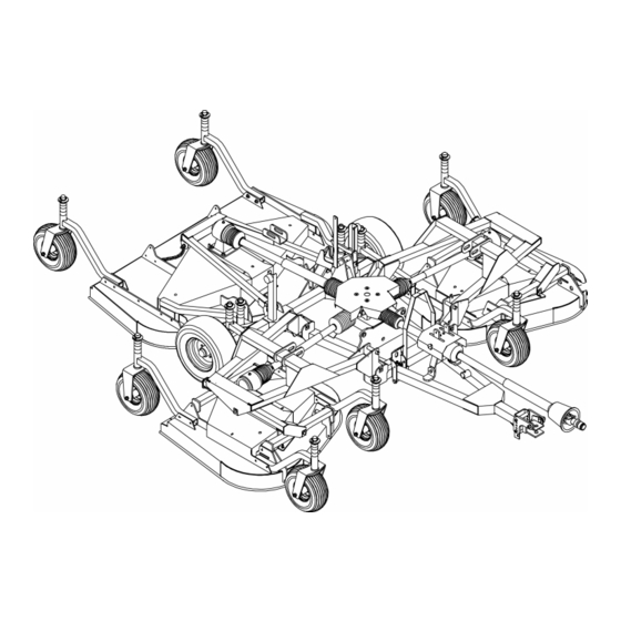
PARTS INDEX Rear Discharge Grooming Mowers: FM1012, FM1015, FM1017 COMMON PARTS MAIN FRAME ASSEMBLY......... . . 38 - 39 TRAILER ASSEMBLY . - Page 38 FM1012, FM1015 & FM1017 MAIN FRAME ASSEMBLY 38 Parts 5WPMAN0183 (Rev. 7/9/2008)
- Page 39 FM1017 – – – – – 1 Left wing assembly (See page 42) 5WP58994 1 Caster arm asy, Left, FM1012 – – – – – 1 Right deck assembly FM1012 -or- (See page 44) -or- 5WP58978 1 Caster arm asy, Left, FM1015, –...
- Page 40 FM1012, FM1015 & FM1017 TRAILER ASSEMBLY 40 Parts 5WPMAN0183 (Rev. 7/9/2008)
- Page 41 – – – – – 1 Trailer frame 5WP3443 Hydraulic Hose holder 5WP62484 Socket, SMV emblem 2 5WP1009501 1 Hitch, Category 1 (FM1012) -or- Screw, HHCS 5/8 NC x 7-1/2 GR5 2 5WP1009502 1 Hitch, Category 2 (FM1015 & Screw, HHCS 5/8 NC x 7 GR5...
- Page 42 Pin, Wing deck link -or- 5WP58982 Pin, Deck link trunnion 5WP1000615 1 Frame, Left wing (FM1017) Pin, Safety 3/16 5WP40907 2 Link, Wing deck lift (FM1012) 5WP71444 Rubber bumper -or- 5WP14139 Nut, Flanged lock 5/16 NC 5WP40881 2 Link, Wing deck lift (FM1015, 5WP38264 Pin, Lynch chain &...
- Page 43 Ring, Retaining int .062 x 1.56 FM1017 all) -or- 51 5WP302178 Nut, Castle 5/8 NF 5WP1001244 1 V-Belt W99 (FM1012 center, FM1015 wings) Pin, Cotter 3/16 x 1-1/2 3 CW Spindle asy (See page 48) Screw, HHCS 1/2 NC x 2-1/2 GR5...
- Page 44 FM1012 WING DECK ASSEMBLY PART DESCRIPTION PART DESCRIPTION 5WP1000609 1 Deck, Weld asy 4 foot left -or- 5WP67131 1 Spring, Ext .177 x 1.22 x 9.88 5WP1000608 1 Deck, Weld asy 4 foot right (NS) 5WP35193 2 Bearing, Ball 5WP40930 1 V-Belt, W80 5WP35141 Ring, Retaining int .062 x 1.56...
-
Page 45: Caster Wheels
CASTER WHEELS ROTATING NON-ROTATING PART DESCRIPTION 5WP38267G Wheel & hub 15.00 x 6.00 x 6 Gray 5WP38476G Wheel rim & hub, 6.00 x 6 w/Cups gray PART DESCRIPTION Grease fitting, 1/8 Pipe thread Non-Rotating: 5WP2306 Bearing, Cup 13A 5WP58987 Sleeve, 1.50 x 1.90 x 1.00 5WP2304 Bearing, Cone 14A 5WP58986... - Page 46 HEIGHT ADJUSTMENT POST PART DESCRIPTION 5WP58998 Sleeve, Drld .81 x 1.25 x 8.00 5WP58999 Wear pad Pin, Spirol .25 x 1.00 5WP35124 Pin, Klik 7/16 x 2 5WP52855 Sleeve, 1.28 x 1.66 x 1.00 5WP52854 Sleeve, 1.28 x 1.66 x .75 5WP52853 Sleeve, 1.28 x 1.66 x .50 Washer, Flat 1-1/4 standard...
-
Page 47: Wing Gearbox Assembly
WING GEARBOX ASSEMBLY PART DESCRIPTION 5WP1002499 Gearbox asy, complete 5WP57458 Gear crown Z25 M5.3 Gearbox housing 5WP1005320 Shaft, Input 1-3/8 -6 5WP1005321 Shaft, Output 1-1/4 5WP57491 Pinion gear Z13 M5.3 5WP57476 Bearing 5WP57462 Bearing 5WP20888 Washer, Protective flat Pin, Cotter 4 x 50 5WP57466 Snap ring 5WP20895... - Page 48 Washer, Lock .929 x 1.66 Washer, Lock 1/4 5WP34440 Bushing, H 1 Strt bore w/key 5WP12622 Sheave, H 1 BK 5.0 PD (FM1012 wing deck & FM1015 rear deck & FM1017 wWing & rear deck) -or- 5WP66694 Sheave, H 1 BK 4.17 PD (FM1012)
- Page 49 5WP1006419 Bracket, Front roller 5WP1006418 Roller, 4 x 7.37 5WP35193 Bearing Standard Hardware, Obtain Locally FM1012 WING DECK ANTI-SCALP ROLLER KIT PART DESCRIPTION 5WP1006421 Roller kit, Front complete 1/2 NC Flanged lock nut 5WP38107 1/2 NC x 9 Cap screw GR5...
- Page 50 FM1012, FM1015 & FM1017 REAR & WING DECK DRIVES (COMER) FM1012 Wing Drive FM1015 Wing Drive PART DESCRIPTION PART DESCRIPTION A 5WP1023226 Drive, Cmpl 40, 21.3 x 32.3 A 5WP1023227 Drive, Cmpl 40, 25.6 x 40.9 1 5WP1026999 Complete collar yoke C12...
- Page 51 FM1012, FM1015 & FM1017 REAR & WING DECK DRIVES (COMER) Check profile and order from correct parts list. Parts 51 5WPMAN0183 (Rev. 7/9/2008)
- Page 52 FM1012, FM1015 & FM1017 REAR & WING DECK DRIVES (WALTERSCHEID) FM1012 Wing Drive FM1015 Wing Drive PART DESCRIPTION PART DESCRIPTION 5WP44628 Drive, Compl 2300, 21.7 x 32.6 5WP44629 Drive, Compl 2300, 26.0 x 41.5 5WP44681 1 Yoke, 1-3/8 - 6 Spline QD...
- Page 53 FM1012, FM1015 & FM1017 REAR & WING DECK DRIVES (WALTERSCHEID) Check profile and order from correct parts list. LIGHTING KIT PART DESCRIPTION 5WP1004486 Lighting kit 1 5WP90401149 Lighting 4 pin LH 2 5WP90401150 Lighting 4 pin RH 5WP1004481 1 Light bracket LH...
- Page 54 CV DRIVE ASSEMBLY (WALTERSCHEID PROFILE) PAGE 55 PAGE 54 PART DESCRIPTION PART DESCRIPTION 5WP44625 Drive, Walterscheid complete CV 11 5WP44688 Guard, Outer half 2480, 35.8 x 48.4 12 5WP44661 Drive, Inner half complete 5WP44671 Yoke, 1-3/8 - 6 Spline QD 13 5WP44677 Yoke, Outer profile 5WP44674...
- Page 55 CV DRIVE ASSEMBLY (WEASLER PROFILE) PAGE 55 PAGE 54 PART DESCRIPTION 5WP1021100 Drive, Weasler complete CV 35R, 35.0 x 47.6 5WP19851 Slide lock repair kit 2 5WP1021301 Yoke QD CV 1-3/8 - 6 5WP52520 U-Joint repair kit 35CV 5WP52522 CV Body w/fitting 5 5WP1021321 Yoke and shaft - CV splined 20.9 6 5WP1024636...
- Page 56 FM1012, FM1015 & FM1017 JACKSHAFT DRIVE ASSEMBLY (WALTERSCHEID) Check profile and order from correct parts list. PART DESCRIPTION PART DESCRIPTION 5WP44626 Drive, Yk & shft non-tel 2400 x 26.4 5WP44678 Shaft, Stub 1-3/8 - 6 x 26.38 5WP38351 Yoke, 1-3/8 - 6 Spline QD...
-
Page 57: Rear Chain Shielding Assembly
REAR CHAIN SHIELDING ASSEMBLY PART DESCRIPTION 5WP55348 Chain shield assembly, 5 ft. deck 5WP53566 Chain shield assembly, 6 ft. deck † Chain shield assembly, 4 ft. deck 5WP1007854 Pin, 40 to 42 chains (5 ft) -or- 5WP1007856 Pin, 52 to 54 chains (6 ft) -or- 5WP1007850 Pin, 31 to 33 chains (4 ft) 5WP4763... - Page 58 HYDRAULIC CYLINDERS Note: The center deck uses a 3 x 8 cylinder. The wing decks use 3 x 10 cylinders. Verify cylinder size before ordering replacement parts. 3 x 8 3 x 10 PART PART DESCRIPTION 5WP29547 5WP1019460 Complete cylinder 5WP19810 5WP19810 Seal repair kit (includes items 2A - 2G...
- Page 59 HYDRAULIC HOSE ASSEMBLY PART DESCRIPTION 5WP1019460 Cylinder, Hydraulic 3 x 10 (See pg 58) 5WP29547 Cylinder, Hydraulic 3 x 8 (See pg 58) 5WP8346 Pin, Headless 1.00 x 4.58 5WP1631 Pin, Headless 1.00 x 3.63 Pin, Cotter 1/4 x 1-3/4 5WP1006404 Hose, 108"...
-
Page 60: Bolt Torque Chart
BOLT TORQUE CHART Always tighten hardware to these values unless a different torque value or tightening procedure is listed for a specific application. Fasteners must always be replaced with the same grade as specified in the manual parts list. Always use the proper tool for tightening hardware: SAE for SAE hardware and Metric for metric hardware. Make sure fastener threads are clean and you start thread engagement properly. -
Page 61: Bolt Size Chart & Abbreviations
BOLT SIZE CHART NOTE: Chart shows bolt thread sizes and corresponding head (wrench) sizes for standard SAE and metric bolts. SAE Bolt Thread Sizes 5/16 Metric Bolt Thread Sizes 10MM 12MM 14MM 16MM 18MM ABBREVIATIONS AG .............. Agriculture MPa............Mega Pascal ASABE.... -
Page 62: Index
INDEX ASSEMBLY Cutting Height Adjustment 14 CV Driveline Turning Limits 14 Dealer Set-up Instructions 34 Leveling Mower 14 Operating 16 DEALER CHECK LISTS On Uneven Terrain 17 Delivery (Dealer’s Responsibility) 36 Technique 16 Pre-Delivery (Dealer’s Responsibility) 36 Tips 16 Removing Mower from Tractor 17 DEALER SERVICE Starting and Stopping Mower 16 Blade Spindle... - Page 63 NOTES Index 63 5WPMAN0183 (Rev. 7/9/2008)
-
Page 64: Product Warranty
Duration Gearbox 5 years from the date of delivery to the components original purchaser GM1060, GM1072, GM1084, FM1012, FM1015, FM1017 and GM1190 3 years from the date of delivery to the Blade spindles original purchaser 3 years from the date of delivery to the... - Page 65 WARRANTY for Replacement Parts Woods Equipment Company (“WOODS”) warrants this product to be free from defect in material and workmanship for a period of ninety (90) days from the date of delivery of the product to the original purchaser with the exception of V-belts, which will be free of defect in material and workmanship for a period of 12 months.
- Page 66 ©2002 Woods Equipment Company. All rights reserved. WOODS and the Woods logo are trademarks of Woods Equipment Company. Frontier Equipment and the Frontier logo are trademarks of Deere & Company. All other trademarks, trade names, or service marks that appear in this...
Need help?
Do you have a question about the FM1012 and is the answer not in the manual?
Questions and answers