
Related Manuals for Frontier FM1015


Summary of Contents for Frontier FM1015
- Page 1 O P E R A T O R ’ S M A N U A L GROOMING MOWERS FM1012 FM1015 FM1017 REAR DISCHARGE Serial Number 1XFFM10XAB0000106 & Above 5WPMAN0862 (Rev. 10/30/2012)
-
Page 2: Introduction
Use only genuine Frontier service parts. Substitute parts will void the warranty and may not meet standards required for safe and satisfactory operation. Record the model number and serial number of your equipment in the spaces... -
Page 3: Table Of Contents
INDEX ........... . . 63 LEA EL INSTRUCTIVO! Si no lee Ingles, pida ayuda a alguien que si lo lea para que le traduzca las medidas de seguridad. SPECIFICATIONS MODEL FM1012 FM1015 FM1017 Cutting Width 12’ 15’ 17’ Cutting Height Range 1.0” - 5.0”... -
Page 4: General Information
GENERAL INFORMATION ARNING ence and these instructions, you should be able to develop procedures suitable to your particular situa- tion. ■ Some illustrations in this manual show the The illustrations and data used in this manual were cur- mower with safety shields removed to provide a rent at the time of printing. -
Page 5: Safety Rules
If guards do not rotate freely on ENTERS SKIN OR EYES. DO NOT DELAY. drivelines, repair and replace bearings before put- ting equipment into service. Never allow children or untrained persons to operate equipment. (Safety Rules continued on next page) Safety 5 Frontier FM (Rev. 1/31/2007) - Page 6 Keep foldable inclines. ROPS systems in “locked up” position at all times. Do not operate PTO during transport. (Safety Rules continued on next page) 6 Safety Frontier FM (Rev. 1/31/2007)
- Page 7 (Safety Rules continued on next page) Safety 7 Frontier FM (Rev. 1/31/2007)
- Page 8 Block equipment securely for storage. and pulley. Use care when installing or removing belt from Keep children and bystanders away from stor- spring-loaded idler. Springs store energy when age area. 8 Safety Frontier FM (Rev. 1/31/2007)
-
Page 9: Safety Decals
SAFETY & INSTRUCTIONAL DECALS ATTENTION! BECOME ALERT! YOUR SAFETY IS INVOLVED! Replace Immediately If Damaged! 1 -5WP18867 FM1015 & FM1017 REAR DECK DANGER (FM1012 SIMILAR) SHIELD MISSING DO NOT OPERATE PUT SHIELD ON 18867--B 5 - Serial Number Plate PRODUCT IDENTIFICATION NUMBER LENEXA, KS, U.S.A. - Page 10 SAFETY & INSTRUCTIONAL DECALS ATTENTION! BECOME ALERT! YOUR SAFETY IS INVOLVED! Replace Immediately If Damaged! 16 - 5WP38446 WING DECK IMPORTANT • OPERATING MOWERS AT RAISED ANGLES EXCEEDING 25 WILL CREATE U-JOINT KNOCKING NOISE AND DAMAGE DRIVELINE. FAILURES RESULTING FROM THIS OPERATION WILL NOT BE COVERED BY WARRANTY.
- Page 11 SAFETY & INSTRUCTIONAL DECALS ATTENTION! BECOME ALERT! YOUR SAFETY IS INVOLVED! Replace Immediately If Damaged! WARNING PIN STORAGE POSITION RAISED MOWER CAN DROP AND CRUSH Before working underneath rear mower: Raise rear mower to transport position. Insert pin to lock transport latch. Securely block up rear of mower.
- Page 12 SAFETY & INSTRUCTIONAL DECALS ATTENTION! BECOME ALERT! YOUR SAFETY IS INVOLVED! Replace Immediately If Damaged! FM1015, FM1017, & FM1012 TRAILER 18 - 5WP1002941 WARNING WARNING TO AVOID SERIOUS INJURY OR DEATH: CRUSHING AND Read Operator's Manual (available from dealer) and follow all safety PINCHING HAZARD precautions.
-
Page 13: Operation 13
OPERATION The operator is responsible for the safe operation of Make sure spring-activated locking pin or collar the cutter. The operator must be properly trained. slides freely and is seated firmly in tractor PTO Operators should be familiar with the cutter, the tractor, spline groove. - Page 14 The PTO drive shaft is intended for use with tractors CV Driveline Turning Limits that have 14 inches between the end of the PTO shaft NOTICE and the tractor's drawbar hitch pin hole. ■ Do not exceed turning angle of 80 degrees at 3.
- Page 15 4. Set mower on the ground. 5. Retighten screws. This equalizes clearance in the bolt holes. 6. Best mowing results will be obtained with front of mower level with, or slightly lower than, the rear. 7. Cutting height is controlled with front and rear caster wheel adjustment.
- Page 16 TRANSPORT 3. Pull the transport lock release rope to disengage the locks. Lower the wings and rear deck and When transporting the mower short distances, raise release the rope. the wings and the rear deck until all three transport locks engage automatically. STARTING AND STOPPING MOWER ARNING Install locking pins to secure the mower wings for...
- Page 17 When engaging the PTO, engine rpm should always be Extremely tall material should be cut twice. Set mower low. Once engaged and ready for mowing, increase at a higher cutting height for the first pass. Then cut at PTO speed to 540 rpm and maintain speed throughout desired height 90 degrees to the first pass.
- Page 18 PRE-OPERATION CHECK LIST NOTES (OWNER's RESPONSIBILITY) ___ Review and follow all safety rules and safety decal instructions on pages 5 through 12. ___ Check that all safety decals are installed and in good condition. Replace if damaged. ___ Check that all shields and guards are properly installed and in good condition.
-
Page 19: Owner Service 19
OWNER SERVICE The information in this section is written for operators who possess basic mechanical skills. If you need help, CAUTION your dealer has trained service technicians available. Always wear relatively tight and belted clothing For your protection, read and follow the safety informa- tion in this manual to avoid getting caught in moving parts. - Page 20 LUBRICATION INFORMATION Be sure to clean fittings thoroughly before attaching grease gun. When applied according to the lubrication chart, one good pump of most guns is sufficient. Use CAUTION SAE 90W gear lube in gearboxes. When lubricating telescoping PTO drives, keep Daily lubrication of PTO slip joints is necessary.
- Page 21 DESCRIPTION FREQUENCY Caster Wheel Pivots 8 Hours Caster Wheel Hubs 8 Hours Blade Spindles 24 Hours Gearbox (Fill 1/2 full with Check For Leaks Daily SAE 90W gear lube Driveline U-Joints 8 Hours Wing Pivots 8 Hours Telescoping Shaft 8 Hours Shield Bearing 8 Hours Deck Pivot...
- Page 22 8. Adjust belt guide G to provide 1/16" to 1/8" clearance from belt. Tighten the bolt to 85 lbs./ft. Rear Deck - FM1012 All Decks - FM1015 & FM1017(Figure 11) CAUTION Use care when installing or removing belt from spring-loaded idler. Springs store energy when extended and, if released suddenly, can cause per- sonal injury.
- Page 23 1. Remove blades. 2. Always sharpen both ends to maintain balance. 3. Follow original sharpening pattern. Figure 11. Belt Routing - FM1015 & FM1017 All Decks & FM1012 Rear Deck 4. Do not sharpen blade to a razor edge. Leave from 1/32"...
- Page 24 Periodically or Before Extended Storage ● Clean large debris such as clumps of dirt, grass, crop residue, etc. from machine. ● Remove the remainder using a low-pressure water spray. 1. Be careful when spraying near scratched or torn safety decals or near edges of decals as water spray can peel decal off surface.
-
Page 25: Troubleshooting
TROUBLESHOOTING MOWING CONDITIONS PROBLEM POSSIBLE CAUSE SOLUTION Grass cut higher in center of Height of mower higher at front Adjust mower height and attitude so that swath than at edge than at rear mower rear and front are within 1/2 inch of same height. - Page 26 TROUBLESHOOTING BELT CONDITIONS PROBLEM POSSIBLE CAUSE SOLUTION Belt slippage Mower overloading; material too Reduce tractor ground speed but tall or heavy maintain full PTO rpm. Cut material twice, one high pass and then mow at desired height. Cut 90 degrees to first pass. Oil on belt from over-lubrication Be careful not to over-lubricate.
-
Page 27: Dealer Service 27
DEALER SERVICE The information in this section is written for dealer ser- 4. Disassemble split taper bushing (5) (located on top vice personnel. The repair described here requires of pulley) by removing the two bolts (2) and special skills and tools. If your shop is not properly washers (4). - Page 28 Spindle Disassembly 3. Place bottom bearing cone into spindle with taper positioned to mate with cup. 1. Place spindle assembly in press and press shaft 4. Identify the open side of the seal containing the down through housing. spring. 2. Remove seals from housing. 5.
- Page 29 Spindle Installation NOTICE ■ Pulley installation sequence is very important for bearing life. Follow the sequence exactly. 1. Install spindle through bottom of mower and secure with four mounting bolts. 2. Install pulley and split taper bushing with integral key on spindle shaft. Make sure bushing is in contact with sleeve on spindle shaft.
- Page 30 Seal Installation NOTE: Proper seal installation is important. An improp- erly installed seal will leak. 1. Clean area in housing where seal outer diameter (OD) seats. Apply a thin coat of Permatex. 2. Inspect area of shaft where seal seats. Remove any burrs or nicks with an emery cloth.
- Page 31 5. Remove vertical shaft seal (18). Replace with new 14. Remove bearing (26) by using a punch and seal (see Seal Replacement, page 29). hammer from the top, outside the housing. Vertical seal should be recessed in housing. Horizontal 15. Support housing upside down (top cover surface) and remove bearing (6) by using a punch and seal should be pressed flush with outside of housing.
- Page 32 12. While holding gear (1) in place, slide input shaft (3) 5. Replace driveline shield. Attach driveline to through gear (1) and bearing (7). Align splines on gearbox. shaft (3) and gear (1). 13. Slide spacer (12) over input shaft (3) and press 1.
- Page 33 2. With snap rings removed, support drive in vise, U-Joint Assembly hold yoke in hand and tap on yoke to drive cup up 1. Place seals securely on bearing cups. Insert cup out of yoke. See Figure 21. into yoke from outside and press in with hand pressure as far as possible.
-
Page 34: 34 Assembly
ASSEMBLY INSTRUCTIONS DEALER SET-UP INSTRUCTIONS The mower is shipped mostly assembled but requires dealer set-up. The Frontier dealer should deliver the mower to the owner completely assembled, lubricated, and adjusted for normal conditions. Recommended torque values for hardware are located on page 61. - Page 35 Attach the mower hydraulic hose to the tractor port. 7. Extra slack in the light wires should be located near Hydraulic quick coupler is not supplied. the wireing harness. Make sure wires cannot become entangled in driveline or hydraulic cylinder. Secure wires to frame tubes above NOTE: The mower hydraulic system should have been cylinder and lock with cable ties.
- Page 36 8. Bracket, Front Roller 9. Roller, 4 x 7.37 10.Bearing Figure 29 FM1012 Rear Deck and FM1015 and FM1017 Front Roller Kit Installation -- Roller Kit, Front Complete 2. 1/2 NC Flange Lock Nut 3. 1/2 NC x 9 HHCS GR5 4.
- Page 37 Hydraulic Latch Release Installation 1. Release Base 2. Slide Channel 3. 3 x 8 Hydraulic Cylinder 4. Bushing 5. Elbow 6. Hose, 108” 7. Pin 1 x 4.08 8. Cotter Pin 9. Flat Washer, 1” 10. 3/8 NC x 1 HHCS GR5 11.
- Page 38 DEALER CHECK LISTS PRE-DELIVERY CHECK LIST DELIVERY CHECK (DEALER’S RESPONSIBILITY) (DEALER’S RESPONSIBILITY) Inspect the equipment thoroughly after assembly to ___ Show customer how to make adjustments and ensure it is set up properly before delivering it to the select proper PTO speed. customer.
-
Page 39: Parts Lists
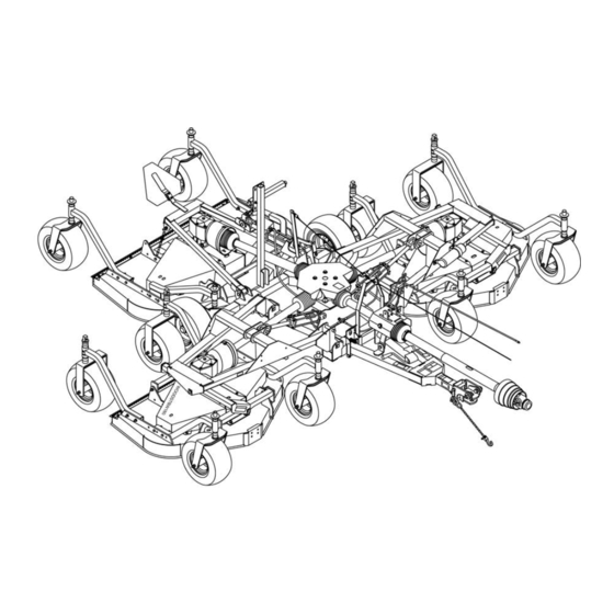
FM1012 REAR DECK & FM1015 & FM1017 FRONT ROLLER ASSEMBLY (OPTIONAL) ....52 FM1017 WING DECK FRONT ROLLER ASSEMBLY (OPTIONAL) ....52 REAR ROLLER ASSEMBLY (OPTIONAL) . - Page 40 FM1012, FM1015 & FM1017 MAIN FRAME ASSEMBLY 40 Parts 5WPMAN0862 (11/22/2010)
- Page 41 FM1012, FM1015 & FM1017 MAIN FRAME ASSEMBLY PART DESCRIPTION PART DESCRIPTION ----- Trailer assembly (see page 42) 5WP38294 1 Rope, .25 x 46.0 ----- Right wing assembly (see 44) 24 5WP1031166 2 Hydraulic cylinder 3 x 10 (see page -----...
- Page 42 FM1012, FM1015 & FM1017 TRAILER ASSEMBLY 42 Parts 5WPMAN0862 (11/22/2010)
- Page 43 FM1012, FM1015 & FM1017 TRAILER ASSEMBLY PART DESCRIPTION PART DESCRIPTION 5WP38298G 2 Wheel & Tire, 20.5 x 8.00 x 10 Gray ----- Trailer frame 5WP38475G Wheel Rim, 5-Bolt 8.00 x 10 Gray 5WP1009501 1 Hitch, Cat 1 -or- 5WP3443 1...
- Page 44 FM1012, FM1015 & FM1017 WING FRAME FM1012 FM1015 FM1017 DESCRIPTION 5WP1032460 5WP1032480 5WP1032490 Frame, right wing 5WP1032461 5WP1032481 5WP1032491 Frame, left wing 5WP1032451 5WP1032455 5WP1032455 Link, wing deck lift 5WP40895 5WP40895 5WP40887 Trunnion, front deck 5WP40896 5WP40896 5WP40888 Trunnion, rear deck...
- Page 45 FM1012 CENTER DECK FM1015 & FM1017 CENTER & WING DECK ASSEMBLY PART DESCRIPTION PART DESCRIPTION 5WP1002048 1 Clutch Shield 5WP1031795 1 5’ Mower Deck (FM1012 Rear, FM1015 Wings) 5WP35141 Ring, Retaining Int .062 x 1.56 5WP1031796 1 6’ Mower Deck (FM1015 Rear, FM1017 All)
- Page 46 FM1012 WING DECK ASSEMBLY PART DESCRIPTION PART DESCRIPTION 5WP35141 2 Ring, Retaining Int .062 x 1.56 5WP1031800 1 4’ Mower Deck, RH -or- * Pin, Cotter 3/16 x 1-1/2 5WP1031801 1 4’ Mower Deck, LH * Washer, Flat 5/16 SAE 5WP40930 1 V-Belt, W80 * Lock Washer, 5/16 ---------- 3 CW Spindle assembly (See...
- Page 47 HEIGHT ADUSTMENT POST PART DESCRIPTION 5WP58993 1 Caster Arm, RH (FM1012) - or - 5WP1031754 1 Caster Arm, RH (FM1015, FM1017) 5WP58994 1 Caster Arm, LH (FM1012) - or - 5WP1031755 1 Caster Arm, LH (FM1015, FM1017) 5WP58998 1 Sleeve, Drid .81 x 1.25 x 8.00...
- Page 48 CASTER ARM & WHEEL ASSEMBLY 48 Parts 5WPMAN0862 (11/22/2010)
- Page 49 CASTER ARM & WHEEL ASSEMBLY FM1012 FM1015 & FM1017 PART DESCRIPTION PART DESCRIPTION 5WP1031703G 1 Wheel 18.00 x 9.50 x 8 Gray 5WP38267G 1 Wheel 15.00 x 6.00 x 6 Gray 5WP1031819G Wheel Rim 9.50 x 8 w/cups Gray 5WP38476G Wheel Rim 6.00 x 6 w/cups Gray...
- Page 50 WING GEARBOX ASSEMBLY PART DESCRIPTION 5WP1002499 1 Gearbox Repair Assembly 5WP57458 1 Gear Crown Z25 M5.3 NS 1 Gearbox Housing 5WP1005320 1 Shaft, Input 1-3/8 -6 5WP1005321 1 Shaft, Output 1-1/4 5WP57491 1 Pinion Gear Z13 M5.3 5WP57476 1 Bearing 5WP57462 1 Bearing 5WP20888 1...
- Page 51 5WP52852 Shaft, Blade Spindle 5WP7144BDKT Blade Kit, High Lift FM1012 Complete (7 blades) 5WP9180BDKT Blade Kit, High Lift FM1015 Complete (9 blades) 5WP9204BDKT Blade Kit, High Lift FM1017 Complete (9 blades) 16 5WP7144BDKT2 Blade Kit, Low Lift FM1012 Complete (7...
- Page 52 FM1012 REAR DECK AND FM1015 & FM1017 FRONT ROLLER ASSEMBLY (OPTIONAL) PART DESCRIPTION 5WD1006417 Front roller kit, complete (one per deck) 1/2 NC Flanged lock nut 5WP38107 1/2 NC x 9 Cap screw GR5 5WP3598 1/2 Flat washer SAE 3/8 NC x 1 Carriage bolt...
- Page 53 REAR ROLLER ASSEMBLY (OPTIONAL) PART DESCRIPTION 5WD1031818 Kit, TBW Rear Roller 5WP1029865 Rear Roller 5WP1031723 Rear Roller Bracket 5WP12305 1/2 NC x 5-1/2 HHCS GR5 1/2 Flat washer SAE 1/2 NC Flange Lock Nut 3/8 NC x 1 Carriage Bolt GR5 3/8 NC Flange Lock Nut Hex Head Cap Screw HHCS...
- Page 54 FM1012, FM1015 & FM1017 REAR & WING DECK DRIVES 54 Parts 5WPMAN0862 (11/22/2010)
- Page 55 FM1012, FM1015 & FM1017 REAR & WING DECK DRIVES FM1012 Wing Drive FM1015 Wing Drive PART DESCRIPTION PART DESCRIPTION 5WP1023226 Drive, Cmpl 40, 21.3 x 32.3 5WP1023227 Drive, Cmpl 40, 25.6 x 40.9 5WP1026999 Complete collar yoke C12 5WP1026999 1...
- Page 56 CV DRIVE ASSEMBLY PART DESCRIPTION PART DESCRIPTION A 5WP1021100 1 Drive, Cmpl CV 35R, 35.0 x 47.6 5WP18864 1 Decal, danger rotating driveline 5WP19851 2 Slide lock repair kit 5WP1021302 1 Outer shield CV 2 5WP1021301 1 Yoke QD CV 1-3/8 - 6 5WP1021303 1 Inner shield CV 5WP52520 2...
- Page 57 JACKSHAFT DRIVE ASSEMBLY PART DESCRIPTION PART DESCRIPTION 5WP1011759 Complete jackshaft drive assembly 5WP30922 6 Retainer, shield 5WP1028775 1 Complete collar yoke 5WP1011757 1 Centering ring 5WP36990 1 U-Joint repair kit 5WP1011755 1 Inner bearing ring 5WP1011756 1 Yoke, outer 5WP1011754 1 Shield, complete (includes 5, 6, 7 &...
- Page 58 HYDRAULIC CYLINDERS Note: The center deck uses a 3 x 8 cylinder. Wing decks use a 3 x 10 cylinder. Verify cylinder size before ordering replacement parts. 3 x 8 3 x 10 PART PART DESCRIPTION 5WP29474 5WP1031166 Complete cylinder 5WP19810 5WP19810 Seal repair kit (includes items 2A - 2G...
- Page 59 LIGHT KIT (OPTIONAL) PART DESCRIPTION 5WD1031385 TBW Light kit 5WP90401149 1 Light, 4 pin right 5WP90401150 1 Light, 4 pin left 5WP1031386 2 Light bracket 5WP1031388 2 Blank .16 x 4.00 x 4.00 5WP1004479 1 Wire harness 3/8 NC x 3-1/2 HHCS GR5 3/8 NC Flange lock nut 1/4 NC x 1 Hex head cap screw GR5 1/4 NC Lock nut...
- Page 60 HYDRAULIC LATCH RELEASE KIT (OPTIONAL) INSTALLATION INSTRUCTION PART DESCRIPTION 5WD1032454 TBW Hydraulic Latch Release Kit 1. Remove four 1/3 NC x 2 hex head cap screws and 5WP1032479 1 Release Base 1/2” flat washers from top of shield on trailer. 5WP1032489 1 Slide Channel 2.
-
Page 61: Bolt Torque Chart
BOLT TORQUE CHART Always tighten hardware to these values unless a different torque value or tightening procedure is listed for a specific application. Fasteners must always be replaced with the same grade as specified in the manual parts list. Always use the proper tool for tightening hardware: SAE for SAE hardware and Metric for metric hardware. Make sure fastener threads are clean and you start thread engagement properly. -
Page 62: Bolt Size Chart & Abbreviations
BOLT SIZE CHART NOTE: Chart shows bolt thread sizes and corresponding head (wrench) sizes for standard SAE and metric bolts. SAE Bolt Thread Sizes 5/16 Metric Bolt Thread Sizes 10MM 12MM 14MM 16MM 18MM ABBREVIATIONS AG .............. Agriculture MPa ............Mega Pascal ASABE ....American Society of Agricultural &... -
Page 63: Index
Owner Service Cutting Height Belt Leveling Mower Installation FM1012 Rear Deck Dealer Check List FM1012 Wing Deck Delivery Check (Dealer’s Responsibility) FM1015 & FM1017 All Decks Pre-Delivery Check List (Dealer’s Responsibility) Replacement Routing Dealer Service Blade Blade Spindle Installation Assembly... - Page 64 ©2002 Woods Equipment Company. All rights reserved. WOODS and the Woods logo are trademarks of Woods Equipment Company. Frontier Equipment and the Frontier logo are trademarks of Deere & Company. All other trademarks, trade names, or service marks that appear in this man-...
Need help?
Do you have a question about the FM1015 and is the answer not in the manual?
Questions and answers