Page 1
O P E R A T O R ’ S M A N U A L GROOMING MOWERS GM1060 GM1072 GM1084 REAR DISCHARGE 5WPMAN0511 (Rev. 10/18/2012)
Page 2
Use only genuine Frontier service parts. Substitute parts will void the warranty and may not meet standards required for safe and satisfactory operation. Record the model number and serial number of your equipment in the spaces...
Make sure driveline guard tether chains are attached to the tractor and equipment as shown in (Safety Rules continued on next page) Safety 5 Frontier GM1060 RD SR (2/14/2006)
Page 6
Weigh the tractor and equipment. Do not estimate. (Safety Rules continued on next page) 6 Safety Frontier GM1060 RD SR (2/14/2006)
Page 7
Follow manual instructions for storage. Make sure all safety decals are installed. Keep children and bystanders away from stor- Replace if damaged. (See Safety Decals section for location.) age area. Safety 7 Frontier GM1060 RD SR (2/14/2006)
SAFETY & INSTRUCTIONAL DECALS ATTENTION! BECOME ALERT! YOUR SAFETY IS INVOLVED! Replace Immediately If Damaged! DANGER DANGER 1 - 5WP15503 SHIELD MISSING DO NOT OPERATE PUT SHIELD ON 18867--B 2 - 5WP18867 ROTATING BLADES AND THROWN OBJECTS Do not put hands or feet under or into mower when PRODUCT IDENTIFICATION NUMBER engine is running.
Page 9
SAFETY & INSTRUCTIONAL DECALS ATTENTION! BECOME ALERT! YOUR SAFETY IS INVOLVED! Replace Immediately If Damaged! (Safety Decals continued from previous page) DAN ER WARNING DANGER CRUSHING AND PINCHING HAZARD UARD MISSIN . ROTATING DRIVELINE Be extremely careful handling various parts of DO NOT OPERATE.
OPERATION The operator is responsible for the safe operation of the mower. The operator must be properly trained. CAUTION Operators should be familiar with the mower, the trac- Always wear relatively tight and belted clothing tor, and all safety practices before starting operation. to avoid getting caught in moving parts.
Page 11
CUTTING HEIGHT ADJUSTMENT ARNING Keep all persons away from operator control area while performing adjustments, service, or maintenance. NOTICE ■ Avoid low cutting heights. Striking the ground with blades produces one of the most damaging shock loads a mower can encounter. Allowing blades to contact ground repeatedly will cause damage to mower and drive.
Page 12
FRONT CASTER ARM CONFIGURATION For GM1060 & GM1072 only The front casters can be set in two positions. Figure 8 shows the two possible configurations for the GM1060 Figure 5. Height Adjustment with Caster Arm Spacers and GM1072 front caster arms.
Page 13
Figure 8. Front Caster Arm Configuration for GM1060 & GM1072 Only To change configurations, remove the cap screws and 1. Raise mower with tractor hydraulics to 16" at nuts and move the arms from one side of the wheel rail dimension C or maximum height of tractor lift, to the other.
Page 14
2. Continue running at least two minutes, allowing Uneven Terrain pulleys to cool. Stopping the mower in contact with ARNING a very hot pulley will bake and ruin belt. Proper ground speed will depend upon the terrain, the Do not operate or transport on steep slopes. height, and type and density of material to be cut.
Page 15
OWNER PRE-OPERATION CHECK LIST ___ Make sure the driveline guards and tether chains are in good condition. Guards must rotate freely (OWNER'S RESPONSIBILITY) on driveline. Fasten tether chains to the tractor ___ Review and follow all safety rules and safety and the equipment as instructed.
OWNER SERVICE The information in this section is written for operators who possess basic mechanical skills. If you need help, your dealer has trained service technicians available. For your protection, read and follow the safety informa- tion in this manual. ARNING Never allow children or untrained persons to operate equipment.
Page 17
DESCRIPTION FREQUENCY Front U-Joint 8 Hours Caster Wheel (Four wheels) 8 Hours Caster Pivot (Four wheels) 8 Hours Left Spindle (Access through hole) 24 Hours Shield Bearings 8 Hours Rear U-Joint 8 Hours Gearbox (Fill to center of horizontal shaft with SAE 80W or 90W Check Daily gear lube) Right Spindle (Access through hole)
Page 18
Figure 13. Belt Routing BELT SERVICE 5. Grasp belt between spindle pulley E, spring loaded idler F and spindle pulley D. Pull spring loaded idler Belt Replacement with belt to obtain enough belt length to route it over pulley E. Make sure spring-loaded idler pivots One of the major causes of belt failure is improper freely with belt installed.
Page 19
Blade Installation 2. Always sharpen both ends at the same time to maintain balance. 3. Follow original sharpening pattern. CAUTION 4. Do not sharpen blade to a razor edge. Leave from Your dealer can supply genuine replacement 1/32" to 1/16" blunt edge. blades.
TROUBLESHOOTING MOWING CONDITIONS PROBLEM POSSIBLE CAUSE SOLUTION Grass cut higher in center of Height of mower higher at front Adjust mower height and attitude so swath than at edge than at rear that mower rear and front are within 1/2 inch of same height. See instructions on page 11.
Page 21
TROUBLESHOOTING BELT CONDITIONS PROBLEM POSSIBLE CAUSE SOLUTION Belt slippage Mower overloading; Material too Reduce tractor ground speed but tall or heavy maintain full PTO rpm. Cut material twice, one high pass and then mow at desired height. Cut at 90 degrees to first pass.
DEALER SERVICE The information in this section is written for dealer ser- 3. Remove jam nut (1) and washer (3) from top of vice personnel. The repair described here requires spindle shaft, Figure 16. special skills and tools. If your shop is not properly 4.
Page 23
Spindle Assembly 4. Apply a thin coat of Permatex to the area of housing where seals seat. Refer to Figure 17. 5. Install bottom seal with spring up toward center of Bearing cones and cups are designed to work together. housing.
Page 25
seal but will clear the housing. Tubing with an OD Gearbox Removal from Mower (Figure 20) that is too small will bow seal cage and ruin seal. 5. Carefully press seal into housing, avoiding distortion to the metal seal cage. 1.
Page 26
Gearbox Disassembly 1. Clean housing, paying specific attention to areas where gaskets will be installed. Refer to Figure 18. 2. Wash housing and all components thoroughly. 1. Remove top cover (22) from housing. Turn gearbox Select a clean area for gearbox assembly. Replace upside down and pour out remaining gear oil from all seals, bearings, and gaskets.
Page 27
19. Check gearbox housing for leaks by plugging all UNIVERSAL JOINT REPAIR holes except one. Apply 4 psi compressed air and immerse the gearbox in water to verify that there are no leaks. 1. Yoke 2. Cup and bearings 20. Remove gearbox from water and dry off with compressed air.
Page 28
3. Clamp cup in vise as shown in Figure 25 and tap 4. Place universal cross in vise as shown in Figure 26 on yoke to completely remove cup from yoke. and tap on yoke to remove cup. Repeat Step 3 for Repeat Step 2 and Step 3 for opposite cup.
● assembly instructions NOTE: Front link with the PTO storage bracket should be installed on right side of mower as shown in Figure DEALER SET-UP INSTRUCTIONS Assembly of this mower is the responsibility of the Rear Offset dealer. If should be delivered to the owner completely Link assembled, lubricated, and adjusted for normal cutting Front...
Page 30
Install Top Link 1. Remove rear caster wheel assembly (20) from shipping position and install as shown in Figure 31 using the same bolts (60) and nuts (44). 2. Repeat for opposite side. 3. Tighten bolts so that caster arm is snug against deck bracket, but not fully torqued.
Page 31
Install Driveshaft 1. Pull locking collar (B) back and, at the same time, push driveline onto tractor gearbox shaft until locking device engages. 2. Attach shield anti-rotation chain (C) to drive shield (2) as shown. Fill Gearbox NOTICE ■ Gearbox is not filled at the factory. Prior to delivery, make sure each gearbox is filled half-full CM768 with 80W or 90W API GL-4 or GL-5 gear lube.
Page 32
CHAIN CUT-TO-LENGTH CHART Model Dimension “A” GM1060 40" GM1072 45" GM1084 50" NOTE: This kit is used on other models. Use only the hardware listed below. 1. Offset link, .38 x 2 x 15" 7. Nut, 1/2 NC flange lock 2.
DEALER CHECK LISTS PRE-DELIVERY CHECK LIST (DEALER’S RESPONSIBILITY) Inspect the equipment thoroughly after assembly to ___ Check all bolts to be sure they are properly ensure it is set up properly before delivering it to the torqued. customer. ___ Check that all cotter pins and safety pins are properly installed.
PARTS INDEX Rear Discharge Grooming Mowers: GM1060 GM1072 GM1084 MAIN FRAME ASSEMBLY ....... 36 - 37 GEARBOX ASSEMBLY.
Page 36
GM1060, GM1072 & GM1084 MAIN FRAME ASSEMBLY 36 Parts 5WPMAN0511 (Rev. 7/18/2008)
Page 37
1 Top Link U-Bracket 5WP19024 5 Screw, 5/8 NC x 1-3/4 Flange HHCS 5WP33647 4 Sleeve 1.05 x 1.31 x .75 (GM1060 & GM1072) -or- * 2 Screw, 5/8 NC x 3 HHCS GR5 5WP52854 4 Sleeve 1.28 x 1.66 x .75 (GM1084) 5WP39254 4 Screw, M8 x 1.25P x 16 mm HHCS...
Page 43
QUICK HITCH KIT (OPTIONAL) CHAIN CUT-TO-LENGTH CHART Model Dimension “A” GM1060 40" GM1072 45" GM1084 50" NOTE: This kit is used on other models. Use only the hardware listed below. PART DESCRIPTION 5WD1005400 Quick Hitch Kit, Complete 5WP1003692 Link, Offset .38 x 2.0 x 15...
BOLT TORQUE CHART Always tighten hardware to these values unless a different torque value or tightening procedure is listed for a specific application. Fasteners must always be replaced with the same grade as specified in the manual parts list. Always use the proper tool for tightening hardware: SAE for SAE hardware and Metric for metric hardware. Make sure fastener threads are clean and you start thread engagement properly.
Page 45
BOLT SIZE CHART NOTE: Chart shows bolt thread sizes and corresponding head (wrench) sizes for standard SAE and metric bolts. SAE Bolt Thread Sizes 5/16 Metric Bolt Thread Sizes 10MM 12MM 14MM 16MM 18MM ABBREVIATIONS AG .............. Agriculture MPa............Mega Pascal ASABE....
Need help?
Do you have a question about the GM1060 and is the answer not in the manual?
Questions and answers
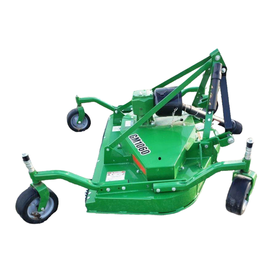
Belt number for gm1072R mower