Table of Contents

Related Manuals for Ferroli Pegasus F3 119


Summary of Contents for Ferroli Pegasus F3 119
-
Page 1: Maintenance Instructions
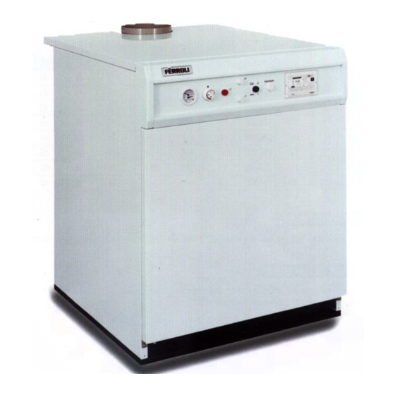
INSTALLATION AND MAINTENANCE INSTRUCTIONS PEGASUS F3 GAS-FIRED CAST-IRON BOILERS WITH ELECTRONIC IGNITION AND FLAME RECTIFICATION MONITORING models 119 - 136 - 153 - 170 - 187 - 221 - 255 - 289 Supplied By www.heating spares.co Tel. 0161 620 6677... - Page 2 Pegasus F3 Supplied By www.heating spares.co Tel. 0161 620 6677...
-
Page 3: Table Of Contents
Contents 1. General technical data 2. Dimensions and technical data 3. Installation 4. Wiring diagrams 5. Startup and shutdown 6. Regulating 7. Fuel conversion 8. Maintenance and cleaning 9. Fault finding Pegasus F3 Supplied By www.heating spares.co Tel. 0161 620 6677... -
Page 4: General Technical Data
1. GENERAL TECHNICAL DATA 1.01 Introduction The Pegasus F 3, with CE approval, is a designed for use with natural gas (G 20) or LPG (G 31) for indirect central heating ahnd hot water. 1.02 Installation requirements Only CORGI registered installers should fit the Pegasus boilers. The boiler installation should comply with relevant British Standards Specifications, codes of practice, and Current Building Regulations, together with any special Regional Requirements of the Local Authorities, Gas Supplier and Insurance Companies. -
Page 5: Technical Data
The boiler is designed to operate with a flow temperaure of 82°C and a maximum ∆t of 20°C HEAT HEAT INPUT HEAT INPUT NUMBER OF OUTPUT (NETT) (GROSS) MODEL SECTIONS Pegasus F3 119 145,4 Pegasus F3 136 165,4 Pegasus F3 153 186,5 Pegasus F3 170 207,6 Pegasus F3 187 228,7... - Page 6 2.03 Main components Front view of the boiler without front casing Fig. 2a Control panel Fig. 2b 10. Incorporated security and Pilot light gas valve (ON-OFF) 1. Temperature-pressure gauge 11. Gas governor 2. Boiler control thermostat 12. Gas pressure switch (set to 5 mbar) 3.
-
Page 7: Installation
2.04 Characteristic pressure drop curve Water pressure drop in all models is shown in fig. 3. The following diagram shows the pressure drop in the boiler as a function of the water flow rate. mbar 6 7 8 9 10 Flow rate Fig. - Page 8 Connect the gas to the boiler in accordance with current regulations. The diameter of the boiler gas inlet does not dictate the choice of diameter for the pipe between the boiler and the gas meter which should be calculated based upon its length and pressure drop. 3.02 Boiler water characteristics When the water supply has a hardness of more than 25 - 30 Fr., it should be treated before entering the heating system to prevent both scaling (caused by hard water) and corrosion (caused by aggressive...
-
Page 9: Wiring Diagrams
4. WIRING AND CONNECTIONS DIAGRAMS Electrical connections should be performed according to the diagrams shown here. Connect the boiler to a single-phase, phase neutral, 230 V ~ 50 Hz power supply through a standard terminal block or outlet with 2A max. fuses connected between the boiler and the power supply. - Page 10 Electrical connections diagram S 4561 B HONEYWELL 5 6 7 230V 50Hz Fig. 4b Spark electrode 114 Water pressure switch (not provided) Pilot burner 116 Gas pressure switch Pump 117 Pilot light gas valve Limit thermostat (manual reset) 129 Ignition lockout reset botton Boiler control thermostat 160 Auxiliary contact Ionisation electrode...
- Page 11 4.02 Access to the internal components of the control panel For access to the terminal block and the internal components of the control panel, proceed as follows: a - Shut off the power supply to the boiler. b - Lift off the boiler cover (held in place by slot pins). c - Unscrew the two screws that hold the plastic panel against the side of the boiler .
-
Page 12: Startup And Shutdown
5. STARTUP AND SHUTDOWN 5.01 Checks to be carried out at first startup It is good practice to check the following at first startup: that the cut-off valves between the boiler and heating system are open; that all is well pressurised and vented; that there are no gas or water leaks from the water system or boiler;... -
Page 13: Regulating
5.05 Inspections and controls after startup At first startup: Make sure the gas supply is perfectly leakproof. Make sure the pilot light is adequate and well adjusted. Test boiler ignition by starting it and turning it off using the control thermostat. Check that no flue products escapes from the boiler draft diverter indicating that either the flue is blocked or the draft is insufficient. - Page 14 6.02 Regulating the flow rate, pre-ignition and speed of opening of the main gas valve Adjusting flow rate · After unscrewing the screws, remove the top cover. · Use a 12-mm hex spanner. · Turn clockwise to reduce the flow rate or anticlockwise to increase it.
-
Page 15: Fuel Conversion
6.03 Pilot burner unit (fig. 8a - 8b) 3 ÷ 4 mm Fig. 8a Combustion chamber cover plate Inspection window Pilot burner Ignitionelectrode Flame rectification probe Pilot injector High tension lead Fig. 8b Pilot gas supply 7. FUEL CONVERSION (from natural to L.P.G.) The following conversion operations are to be performed by qualified personnel only. - Page 16 7.01 Dismantling the main burner · Turn off the gas cock and switch off the power supply to the boiler. · Dis-connect and isolate gas governor. · Unscrew the two screws that fasten the main burner to the boiler. · Disconnect the cables from the electrodes.
-
Page 17: Maintenance And Cleaning
8. MAINTENANCE AND CLEANING The following operations are to be performed by qualified personnel only. 8.01 Seasonal inspection of the boiler and flue Before the beginning of winter you should perform a general inspection of the boiler, heating system and flue. The inspection should verify: That the boiler flueways, burner and flue are clean. -
Page 18: Fault Finding
9. FAULT FINDING Fault Cause and Corrective Action The pilot burner is clogged or dirty. After a few startup attempts, the electronic control unit fails to ignite the boiler Check that the gas flow to the boiler is normal and that air in the pipes has been removed. - Page 19 No rise in temperature Make sure the regulating thermostat works. while the boiler is working Check that gas consumption is not below specifica- tions. Check that the boiler is perfectly clean. Check that the boiler rating is in proportion to the system.
- Page 20 ALL SPECIFICATIONS SUBJECT TO CHANGE Stockton Close, Minworth Industrial Park, Minworth, Sutton Coldfield, West Midlands B76 8DH Tel.: 0121/3523500 - Fax 0121/3523510 Supplied By www.heating spares.co Tel. 0161 620 6677...
Need help?
Do you have a question about the Pegasus F3 119 and is the answer not in the manual?
Questions and answers